Sequential Circuits Prophet-5 Service Manual - Audiofanzine
Sequential Circuits Prophet-5 Service Manual - Audiofanzine
Sequential Circuits Prophet-5 Service Manual - Audiofanzine

Create successful ePaper yourself
Turn your PDF publications into a flip-book with our unique Google optimized e-Paper software.
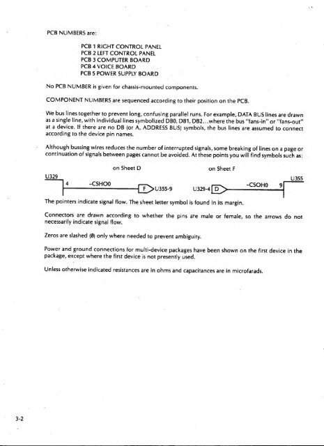
PCB NUMBERS are:PCS 1RIGHT CONTROL PANELPCB 2 LEFT CONTROL PANELPCB 3 COMPUTER BOARDPCB 4 VOICE BOARDPCB 5 POWER SUPPLY BOARDNo PCB NUMBER isgiven for chassis-mounted components.COMPONENT NUMBERS are sequenced according to their position on the PCB.We bus lines together to prevent long; confusing parallel runs. For example, DATA BUS lines are drawnas a single line, with individual lines symbolized DBO, DB1, DB2. ..where the bus "fans-in" or ''fans-out"at a device. If there are no DB (or A, ADDRESS BUS) symbols, the bus lines are assumed to connectaccording to the device pin names.Although bussing wires reduces the number of interrupted signals, some breaking of lines on a page orcontinuation of signals between pages cannot be avoided. At these points you will find symbols such as:on Sheet Don Sheet FU3294 -CSHOOU355-9 U329-4 D-CSOHOU355The pointers indicate signal flow. The sheet letter symbol is found In its margin.Connectors are drawn according to whether the pins are male or female, so the arrows do notnecessarily Indicate signal flow.Zeros are slashed (0)only where needed to prevent ambiguity.Power and ground connections for multi-device packages have been shown on the firstpackage, except where the first device isnot presently used.device in theUnless otherwise indicated resistances are in ohms and capacitances are inmicrofarads.3-2