WESTERBEKE GASOLINE GENERATOR
WESTERBEKE GASOLINE GENERATOR
WESTERBEKE GASOLINE GENERATOR
- No tags were found...

You also want an ePaper? Increase the reach of your titles
YUMPU automatically turns print PDFs into web optimized ePapers that Google loves.
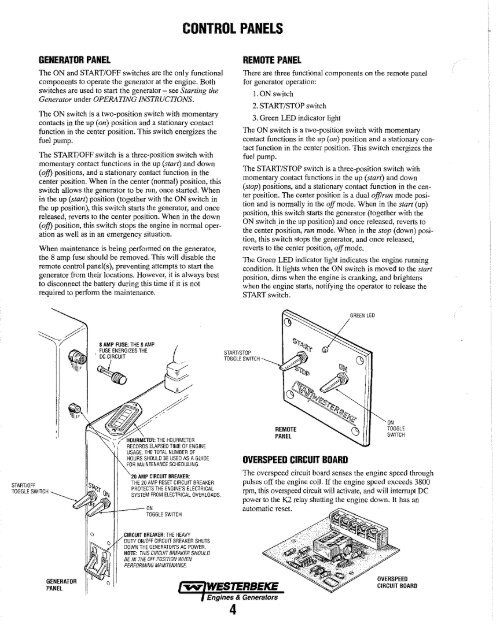
CONTROL PANELS<strong>GENERATOR</strong> PANELThe ON and START/OFF switches are the only functionalcomponents to operate the generator at the engine. Bothswitches are used to start the generator - see Starting theGenerator under OPERATING INSTRUCTIONS.The ON switch is a two-position switch with momentarycontacts in the up (on) position and a stationary contactfunction in the center position. This switch energizes thefuel pump.The START/OFF switch is a three-position switch withmomentary contact functions in the up (start) and down(off) positions, and a stationary contact function in thecenter position. When in the center (normal) position, thisswitch allows the generator to be run, once started. Whenin the up (start) position (together with the ON switch inthe up position), this switch starts the generator, and oncereleased, reverts to the center position. When in, the down(off) position, this switch stops the engine in nonnal operationas well as in an emergency situation.When maintenance is being performed on the generator,the 8 amp fuse should be removed. This will disable theremote control panel(s), preventing attempts to start thegenerator from their locations. However, it is always bestto disconnect the battery during this time jf it is notrequired to perfonn the maintenance.REMOTE PANELThere are three functional components on the remote panelfor generator operation:LON switch2. START/STOP switch3. Green LED indicator lightThe ON switch is a two-position switch with momentarycontact functions in the up (Oil) position and a stationary contactfunction in the center position. This switch energizes thefuel pump.The START/STOP switch is a three-position switch withmomentary contact functions in the up (start) and down(stop) positions, and a stationary contact function in the centerposition. The center position is a dual offJrun mode positionand is normally in the off mode. When in the start (up)position, this switch starts the generator (together with theON switchin the up position) and once released, reverts tothe center position, run mode. When in the stop (down) position,this switch stops the generator, and once released,reverts to the center position, off mode.The Green LED indicator light indicates the engine runningcondition. It lights when the ON switch is moved to the startposition, dims when the engine is cranking, and brightenswhen the engine starts, notifying the operator to release theSTART switch.,8 AMP FUSE: THE 8 AMPFUSE ENERGIZES THE. DC CIRCUITSTART/STOPTOGGLE SWITCHSTART/OFFTOGGLE SWlTCHHOURMffiR: THE HOURMETERRECORDS ELAPSED TIME OF ENGINEUSAGE. THE TOTAL NUMBER OFHOURS SHOULD BE USED AS A GUIDEFOR MAINTENANCE SCHEDULING.~-I+ ___ ON20 AMP CIRCUIT BREAKER:THE 20 AMP RESET CIRCUIT BREAKERPROTECTS THE ENGINE'S ELECTRICALSYSTEM FROM ELECTRICAL OVERLOADS.TOGGLE SWITCHREMOTEPANELOVERSPEED CIRCUIT BOARDONTOGGLESWITCHThe overspeed circuit board senses the engine speed throughpulses off the engine coil. If the engine speed exceeds 3800rpm, this overspeed circuit will activate, and will interrupt DCpower to the K2 relay shutting the engine down. It has anautomatic reset.CIRCUIT BREAKER: THE HEAVYDUTY ON/OFF CIRCUIT BREAKER SHUTSDOWN THE <strong>GENERATOR</strong>'S AC POWER.NOTE: THIS CIRCUIT BREAKER SHOULDBE IN THE OFF POSITION WHENPERFORMING MAINTENANCE.<strong>GENERATOR</strong>PANEla~ <strong>WESTERBEKE</strong>Engines & Generators4OVERSPEEDCIRCUIT BOARD