WESTERBEKE GASOLINE GENERATOR
WESTERBEKE GASOLINE GENERATOR
WESTERBEKE GASOLINE GENERATOR
- No tags were found...

You also want an ePaper? Increase the reach of your titles
YUMPU automatically turns print PDFs into web optimized ePapers that Google loves.
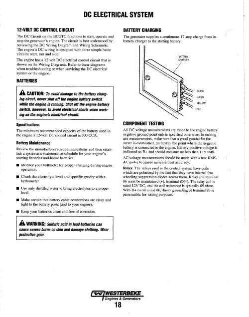
DC ELECTRICAL SYSTEM12-VOLT DC CONTROL CIRCUITThe DC Circuit on the BCGTC functions to start, operate andstop the generator's engine. The circuit is best understood byreviewing the DC Wiring Diagram and Wiring Schematic.The engine's DC wiring is designed with three simple basiccircuits: start, run and stop.The engine has a 12 volt DC electrical control circuit that isshown on the Wiring Diagrams. Refer to these diagramswhen troubleshooting or when servicing the DC electricalsystem or the engine.BAmRIESA CAUTION: To avoid damage to the banery chargingcircut, never shut off the engine banery switchwhile the engine is running. Shut off the engine baneryswitch, however, to avoid electrical shorts when workingon the engine's electrical circuit.SpecificationsThe minimum recommended capacity of the battery used inthe engine's 12-volt DC control circuit is 300 CCA.Battery MaintenanceReview the manufacturer's recommendations and then establisha systematic maintenance schedule for your engine'sstarting batteries and house batteries.• Monitor your voltmeter for proper charging during engineoperation.• Check the electrolyte level and specific gravity with ahydrometer.• Use only distilled water to bring electrolytes to a properlevel.• Make certain that battery cable connections are clean andtight to the battery posts (and to your engine).BATTERY CHARGINGThe generator supplies a continuous 17 amp charge from itsbattery charger to the starting battery.COMPONENT TESTINGBATIERYCHARGERBLACKGREENYELLOWAll DC voltage measurements are made to the engine batterynegative ground point unless specified otherwise. In makingtest measurements, make sure that a good ground for themeter is established, preferably the point where the negativebattery is connected to the engine. Battery positive voltage isindicated as B+ and should measure no Jess than 11.5 volts.AC voltage measurements should be made with a true RMSAC meter to insure measurement accuracy.Relay. The relays used in the control system have coilswhich are polarized by the fact that they have internal freewheeling suppression diodes across them. Relay coil terminal86 must be maintained (+), tenninaI85(-). The relay coil israted 12V DC, and the coil resistance is typically 85 ohms.With B+ on terminal 86, direct grounding of terminal 85 ispermissible for testing purposes.RED• Keep your batteries clean and free of corrosion.A WARNING: Sulfuric acid in lead baneries cancause severe burns on skin and damage clothing. Wearprotective gear.~ <strong>WESTERBEKE</strong>Engines & Generators18