LAY-UP & RECOMMISSIONINGINTAKE MANIFOLDClean the filter screen in the flame arrester, and place a cleandoth lightly soaked in lube oil around the flame arrester toblock any opening. Also place an oil-soaked cloth in thethrough-hull exhaust port. Make a note to remove cloths prior tostart-up!STARTER MOTORLubrication and cleaning of the starter drive pinion is advisable,if access to the starter permits its removal. Make sure the batteryconnections are shut off before attempting to remove thestarter. Take care in properly replacing any electrical connectionsremoved from the starter.CYLINDER LUBRICATIONSpray fogging oil into the open air intake, with the flamearrestor removed, while the generator is running. The foggingoil will stall out the engine and coat the valves, cylinders andspark plugs for winter protection.NOTE: The spark plugs will need to be removed for cleaningand regapping at spring commissioning.SPARE PARTSLay-up time provides a good opportunity to inspect your<strong>WESTERBEKE</strong> engine to see if external items such as drivebelts or coolant hoses need replacement. Check your basicspares kit and order items not on hand, or replace those itemsused during the lay-up, such as filters and zinc anodes.RECOMMISSIONINGThe recommissioning of your <strong>WESTERBEKE</strong> engine after aseasonal lay-up generally follows the same procedures asthose presented in the PREPARATIONS FOR INITIAL STARTUP section regarding preparation for starting and normalstarts. However, some of the lay-up procedures will need tobe counteracted before starting the engine.1. Remove the oil-soaked cloths from the intake manifoldand from the through-hull exhaust port.2. Remove the raw water pump cover and gasket. Discard thegasket. Install the raw water pump impeller removed duringlay-up (or a replacement, if required). Install the rawwater pump cover with a new cover gasket.3. Remove the spark plugs, wipe clean, re-gap, and install toproper tightness.4. Reinstall the batteries that were removed during the layup,and reconnect the battery cables, making sure the terminalsare clean and that the connections are tight. Checkto make sure the batteries are fully charged.5. Note that it is not necessary to flush the antifreeze/freshwater solution from the raw water coolant system. Whenthe engine is put into operation, the system will self-flushin a short period of time with no adverse affects.6. Start the engine in accordance with procedures in thePREPARATIONS FOR INITIAL SDlRT-UP section of thismanual.BATTERIESIf batteries are to be left on ·board during the lay-up period,make sure that they are fully charged, and will remain thatway, to prevent them from freezing. If there is any doubt thatthe batteries will not remain fully charged, or that they willbe subjected to severe environmental conditions, remove thebatteries and store them in a wanner, more compatible environment.A WARNING: Lead acid batteries emit hydrogen, ahighly·explosive gas, which can be ignited by electri·cal arcing or a lighted cigarette, cigar, or pipe. Do notsmoke or allow an open flame near the battery beingserviced. Shut off all electrical equipment in thevicinity to prevent electrical arcing during servicing.Engines & Generators35
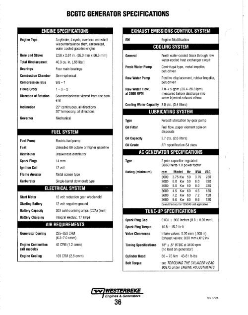
BCGTC <strong>GENERATOR</strong> SPECIFICATIONSENGINE SPECIFICATIONSEngine TypeBore and StrokeTotal DisplacementBearingsCombustion ChamberCompression ratio 9.8 - 13 cylinder, 4 cycle, overhead camshaftwlcounterbalance shaft, carbureted,water cooled gasoline engine2.56 x 2.61 in. (65.0 mm x 66.3 mm)40.3 cu. in. (.66 liter)Four main bearingsSemi-sphericalFiring Order 1 - 3 - 2Direction of RotationInclinationGovernorFuel PumpFuelDistributorSpark PlugsIgnition CoilFlame ArresterCarburetorStart MotorStarting BatteryBattery CapacityBattery ChargingGenerator CoolingEngine Combustion(all models)Engine CoolingCounterclockwise viewed from the backend25 0 continuous, all directions30 0 temporary, all directionsMechanicalFUEL SYSTEMElectric fuel pumpUnleaded 89 octane or higher gasolineBreakerless distributor14 mm12 voltMetal screen typeSingle-barrel downdraft typeELECTRICAL SYSTEM -12 volt reduction gear wlsolenoid12 volt negative ground300 cold cranking amps (CCA) (min)Integral electriC, 17 ampsAIR REQUIREMENTS225--250 CFM(6.3-7.0 cmm)42 CFM (1.2 cmm)100 CFM (2.8 cmm)GeneralFresh Water PumpRaw Water PumpRaw Water Flow,at 3600 RPMFresh water-cooled block through rawwater-cooled heat exchanger circuitCentrifugal type, metal impeller,belt-drivenPositive displacement, rubber impeller,belt-driven7.0-7.5 gpm (26.4-28.3 Ipm)measured before discharge intowater injected exhaust elbow.Cooling Water Capacity 3.5 qts. (3.4 liters)TypeOil FilterOil CapacityOil GradeTypeLUBRICATING SYSTEMForced lubrication by gear pumpFuel flow, paper element spin-ondisposals2.7 qts. (2.6 liters)API specification SJ classAC <strong>GENERATOR</strong> SPECIFICATIONS2 pole capacitor regulated50/60 hertz-1.0 power factorRating (minimum) r~m Model Hz KVA VAC3000 3.75 Kw 50 3.75 2303000 6.0 Kw 50 6.0 2303000 8.0 Kw 50 8.0 2303600 4.5 Kw 60 4.5 1203600 7.2 Kw 60 7.2 1203600 9.6 Kw 60 9.6 120Consult factory for 120/240 volt applicationSpark Plug GapSpark Plug TorqueValve ClearancesTUNE-UP SPECIFICATIONS0.031 ± .002 inches (0.8 ± 0.05 mm)10.8 - 15.2 Ib-ftIntake valves: 0.20 mm (.008 in)Exhaust valves: 0.30 mm (.012 in)Timing Specifications 18 0 ± .5 0 BTDC at 3600 rpm(no load on generator)Cylinder HeadBoll Torque60 - 70 Nm 43-51 ft-Ibssee TORQUING THE CYLINDER HEADBOLTS under ENGINE ADJUSTMENTS-..v- <strong>WESTERBEKE</strong>Engines & Generators36Rev. 6/1/98