gc columns
gc columns
gc columns
- No tags were found...

Create successful ePaper yourself
Turn your PDF publications into a flip-book with our unique Google optimized e-Paper software.
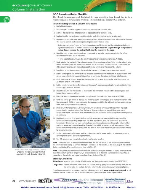
GC COLUMNS | CAPILLARY COLUMNSColumn InstallationScott Grossman, Applications ChemistChecking for leaks, using a thermalconductivity leak detector (step 13).GC Column Installation ChecklistThe Restek Innovations and Technical Services specialists have found this to be areliable sequence for avoiding problems when installing a capillary GC column.Instrument Preparation & Column Installation1. Cool all heated zones.2. Visually inspect indicating oxygen and moisture traps. Replace saturated traps.3. Examine the inlet and the detector. Clean or replace all dirty or corroded parts.4. Replace the inlet liner and septum, and the injector seals (O-rings, inlet seals, ferrules, etc.).5. Mount the column in the oven with a support that protects it from scratches. Center the column in the oven.This ensures uniform heat exposure generating consistent retention times.•Restek has two types of cages for fused silica <strong>columns</strong>, an 11-pin cage and the original cage that useshigh temperature string to hold the column in place. If you have the cage with high temperaturestring, do not remove the string that holds the column in the cage!6. Uncoil the ends to make sure the ends are long enough to reach the injector and detector. Cut a fewcentimeters from each end of the column.•To cut a fused silica column, use the smooth edge of a ceramic scoring wafer (cat.# 20116).7. While pointing the inlet end of the column downward (to prevent shards from falling into the column), slidethe nut and appropriate size ferrule onto the inlet end of the column. Cut an additional 2 cm from the endof the column to remove any material scraped from the ferrule onto the edge of the column.8. Install the column the appropriate distance in the injector, as indicated in your instrument manual.9. Set the carrier gas to the flow rate or inlet pressure recommended for the column or to your method flowrate/pressure. Confirm presence of column flow by immersing the column outlet in a vial of solvent.10. Flush the column at ambient temperature with carrier gas: at least 5 minutes for a 25-30 m column and10 minutes for a 50-60 m column.11. Set the injector temperatures. Do not exceed the column’s maximum operating temperature (listed on thecolumn tag). Check inlet for leaks.12. Install the column into the detector as described in the instrument manual. Set the detector gases andtemperatures to proper settings.13. Check the detector connections for leaks, using a Restek Electronic Leak Detector (cat.# 22839).14. Verify the carrier gas flow is at the rate you intend to use for your analysis. (Use the Restek ProFlow 6000flowmeter, cat.# 22656, to ensure accurate flow measurement.) Set the split vent, septum purge, and anyother applicable gas rates as appropriate.15. Inject an unretained compound, to verify the column is installed correctly and to determine the deadvolume time for checking column flow. The type of detector and column type will determine whichcompound to inject. A symmetric peak indicates the column is installed correctly. Adjust the carrier gas flowas necessary.16. Condition the column 20 °C above the final analysis temperature of your method. Do not exceed thecolumn’s maximum operating temperature. For most applications, 1 hour of conditioning is sufficient.For sensitive detectors or low level analysis, longer conditioning times or conditioning the column at themaximum temperature may be beneficial. Extended time at high temperatures will not adversely affectcolumn performance as long as precautions are taken to make sure the carrier gas is clean and is filteredfor oxygen and water.17. To check instrument performance, analyze a column test mix for a new method, or a known standard toconfirm proper column and system performance.18. Your GC system is now ready to be calibrated and acquire samples.Note 1: For some types of sensitive detection systems, like MS, PID and PDD, it is recommended to conditionthe column as listed in Step 16 without making the connection to the detector. In this case, plug off the detectorduring conditioning. After conditioning, continue with Step 12.Note 2: Also, when you intend to condition thick-film coated <strong>columns</strong> (film thickness > 1 µm) at temperaturesnear the maximum operation temperature, it is recommended to do the initial 1-2 hrs conditioning without aconnection to the detector and repeat procedure above, starting at Step 12.Standby ConditionsShort-Term: leave the column in the GC with carrier gas flowing at an oven temperature of 100-150°C.Long-Term: remove the column from the GC and seal the ends by gently and carefully pushing each end intothe curved edge of a septum. Store the column in the original box away from strong lighting.If you have any questions or problems installing a Restek column, visit www.restek.com/<strong>gc</strong>install or callTechnical Service at 800-356-1688 or 814-353-1300, ext. 4, or contact your Restek representative.30 www.restek.comWebsite : www.chromtech.net.au E-mail : info@chromtech.net.au TelNo : 03 9762 2034 . . . in AUSTRALIA Mar 2011