GC COLUMNS | PLOT COLUMNSPLOT Column SelectionNext Generation of Porous Layer Open Tubular (PLOT) Columns• Stabilized particle layers improve robustness and reproducibility of retention and flow.• Fully compatible with valve switching and Deans switching systems.• Highly efficient, reproducible analyses; ideal for permanent gases, solvents, and hydrocarbons.• New manufacturing procedure reduces particle generation and improves performance of porouspolymers, molecular sieves, and PLOT <strong>columns</strong>.Porous layer open tubular (PLOT) <strong>columns</strong> are very beneficial for solving application problems, especiallyfor the analysis of volatile compounds. PLOT <strong>columns</strong> have a unique selectivity, allowing for the separationof gaseous compounds at room temperature. Due to the adsorption mechanism of the supportsused in PLOT <strong>columns</strong>, permanent gases and light hydrocarbons can be resolved at room temperature;<strong>columns</strong> can then be programmed to higher temperatures to elute higher boiling compounds.Traditional PLOT Columns Offer Poor StabilityThe traditional PLOT column is built with a 5-50µm layer of particles adhered to the tubing walls. Becausethis layer of particles generally lacks stability, PLOT <strong>columns</strong> must be used very carefully, as particle releaseis common and can cause unpredictable changes in retention time and flow behavior. PLOT <strong>columns</strong> generallymust be used in conjunction with particle traps to prevent the contamination of valves, injectors, andGC detectors. Figure 1 shows an example of particle accumulation resulting in a blockage inside a Press-Tight® liner. If particle traps are not used, particles will hit the detector resulting in electronic noise, seen asspikes on the baseline. In the case of valves, particles can become lodged in the valve and result in leaks.Figure 1 Particles released from traditional PLOT <strong>columns</strong> can cause blockages.Particles forming a "plug".New PLOT Columns Minimize Particle ReleaseRestek has developed new procedures to manufacture PLOT <strong>columns</strong> with concentric stabilized adsorptionlayers. These new generation PLOT <strong>columns</strong> show a constant flow behavior (permeability) and havesignificantly improved mechanical stability, resulting in easier operation, better chromatography, andreduced particle release. Greater particle stability means more reproducible retention times, virtually nospiking, and longer column lifetimes. This innovative stabilization chemistry technology is currentlyapplied to Rt®-Alumina BOND, Rt®-Msieve 5A, Rt®-Q-BOND, Rt®-QS-BOND, Rt®-S-BOND, andRt®-U-BOND fused silica <strong>columns</strong>. It is also available for select metal <strong>columns</strong> including MXT®-AluminaBOND and MXT®-Msieve 5A <strong>columns</strong>.Consistent Flow Restriction Factor (F) Guarantees Reproducible FlowThick layers of particles are difficult to deposit in a homogeneous layer and, in traditionally manufacturedPLOT <strong>columns</strong>, this results in variable coating thicknesses. The positions where the layer is thicker act asrestrictions and affect flow (Figure 2). Depending on the number and intensity of these restrictions, traditionalPLOT <strong>columns</strong> often show greater variation in flow restriction than wall coated open tubular(WCOT) <strong>columns</strong>. In practice, conventional PLOT <strong>columns</strong> with the same dimensions can differ in flowby a factor of 4-6, when operated at the same nominal pressure. For applications where flow is important,such as with Deans switching, the nonreproducible flow behavior of most commercially available PLOT<strong>columns</strong> is a problem.Figure 2 Inconsistent coating thicknesses result in restrictions that cause significantvariation in flow.Ideal open path columnPLOT column with restriction106 800-356-1688 or 814-353-1300Website : www.chromtech.net.au E-mail : info@chromtech.net.au TelNo : 03 9762 2034 . . . in AUSTRALIA Mar 2011
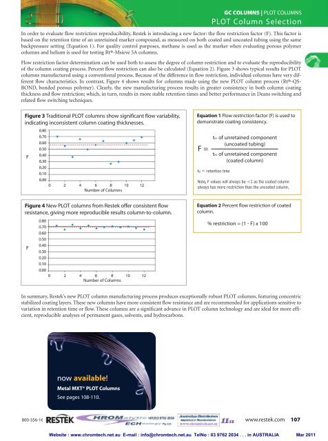
GC COLUMNS | PLOT COLUMNSPLOT Column SelectionIn order to evaluate flow restriction reproducibility, Restek is introducing a new factor: the flow restriction factor (F). This factor isbased on the retention time of an unretained marker compound, as measured on both coated and uncoated tubing using the samebackpressure setting (Equation 1). For quality control purposes, methane is used as the marker when evaluating porous polymer<strong>columns</strong> and helium is used for testing Rt®-Msieve 5A <strong>columns</strong>.Flow restriction factor determination can be used both to assess the degree of column restriction and to evaluate the reproducibilityof the column coating process. Percent flow restriction can also be calculated (Equation 2). Figure 3 shows typical results for PLOT<strong>columns</strong> manufactured using a conventional process. Because of the difference in flow restriction, individual <strong>columns</strong> have very differentflow characteristics. In contrast, Figure 4 shows results for <strong>columns</strong> made using the new PLOT column process (Rt®-QS-BOND, bonded porous polymer). Clearly, the new manufacturing process results in greater consistency in both column coatingthickness and flow restriction; which, in turn, results in more stable retention times and better performance in Deans switching andrelated flow switching techniques.Figure 3 Traditional PLOT <strong>columns</strong> show significant flow variability,indicating inconsistent column coating thicknesses.Equation 1 Flow restriction factor (F) is used todemonstrate coating consistency.FF =tR1 of unretained component(uncoated tubing)tR2 of unretained component(coated column)tR = retention timeNumber of ColumnsNote, F values will always be