LECTURE 040 –DIGITAL PHASE LOCK LOOPS (DPLLs)
LECTURE 040 –DIGITAL PHASE LOCK LOOPS (DPLLs)
LECTURE 040 –DIGITAL PHASE LOCK LOOPS (DPLLs)

You also want an ePaper? Increase the reach of your titles
YUMPU automatically turns print PDFs into web optimized ePapers that Google loves.
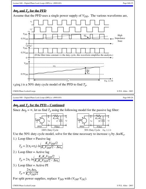
Lecture <strong>040</strong> – Digital Phase Lock Loops (<strong>DPLLs</strong>) (09/01/03) Page <strong>040</strong>-25∆ω p and T p for the PFDAssume that the PFD uses a single power supply of V DD . The various waveforms are,v 1V DD0.5V DDv 2 'v d0 tv d (eq.)V DDv dHighImpedanceState0.5V DD(If the filter time constant >> the duty cycle, this waveform simplifies the analysis.)0 tv fV DD0.5V DDω 1∆ωKov d (eq.) is a 50% duty cycle model of the PFD to find T p .T PtFig. 2.2-30CMOS Phase Locked Loops © P.E. Allen - 2003Lecture <strong>040</strong> – Digital Phase Lock Loops (<strong>DPLLs</strong>) (09/01/03) Page <strong>040</strong>-26∆ω p and T p for the PFD – ContinuedSince ∆ω p = ∞, let us find T p using the following model for the passive lag filter:+V R DD1 +R 2v2d C-PFDFilter100% Duty Cycle+v f-V DD2PFD+v d-R 1 +R 22CFilter+v f-50% Duty Cycle Fig. 2.2-31Use the 50% duty cycle model, solve for the time necessary to increase v f by ∆ω/K o .1.) Loop filter = Passive lag⎛ K⎜ o V DD /2 ⎞⎟T p = 2(τ 1 +τ 2 ) ln⎜⎟⎝K o V DD /2 - ∆ω o ⎠2.) Loop filter = Active lag⎛ K⎜ o K a V DD /2 ⎞⎟T p = 2τ 1 ln⎜⎟⎝K o K a V DD /2 - ∆ω o ⎠3.) Loop filter = Active PIT p = 2τ 1∆ω oK o V DD /2For split power supplies, replace V DD with (V OH -V OL ).CMOS Phase Locked Loops © P.E. Allen - 2003