LECTURE 040 –DIGITAL PHASE LOCK LOOPS (DPLLs)
LECTURE 040 –DIGITAL PHASE LOCK LOOPS (DPLLs)
LECTURE 040 –DIGITAL PHASE LOCK LOOPS (DPLLs)

You also want an ePaper? Increase the reach of your titles
YUMPU automatically turns print PDFs into web optimized ePapers that Google loves.
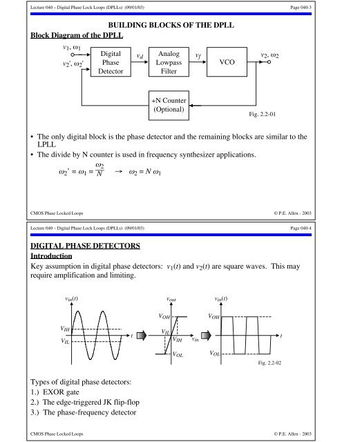
V OLFig. 2.2-02Lecture <strong>040</strong> – Digital Phase Lock Loops (<strong>DPLLs</strong>) (09/01/03) Page <strong>040</strong>-3BUILDING B<strong>LOCK</strong>S OF THE DPLLBlock Diagram of the DPLLv 1 , ω 1DigitalAnalogv 2 , ω 2v 2 ', ω 2 ' PhaseDetectorLowpassFilterVCOv d v fFig. 2.2-01÷N Counter(Optional)• The only digital block is the phase detector and the remaining blocks are similar to theLPLL• The divide by N counter is used in frequency synthesizer applications.ω 2 ’ = ω 1 = ω 2N → ω 2 = N ω 1CMOS Phase Locked Loops © P.E. Allen - 2003Lecture <strong>040</strong> – Digital Phase Lock Loops (<strong>DPLLs</strong>) (09/01/03) Page <strong>040</strong>-4DIGITAL <strong>PHASE</strong> DETECTORSIntroductionKey assumption in digital phase detectors: v 1 (t) and v 2 (t) are square waves. This mayrequire amplification and limiting.v in (t)V IHV ILtv outV OHV ILV IHV OLv inV OHv in (t)tTypes of digital phase detectors:1.) EXOR gate2.) The edge-triggered JK flip-flop3.) The phase-frequency detectorCMOS Phase Locked Loops © P.E. Allen - 2003