LECTURE 040 –DIGITAL PHASE LOCK LOOPS (DPLLs)
LECTURE 040 –DIGITAL PHASE LOCK LOOPS (DPLLs)
LECTURE 040 –DIGITAL PHASE LOCK LOOPS (DPLLs)

You also want an ePaper? Increase the reach of your titles
YUMPU automatically turns print PDFs into web optimized ePapers that Google loves.
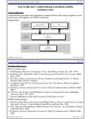
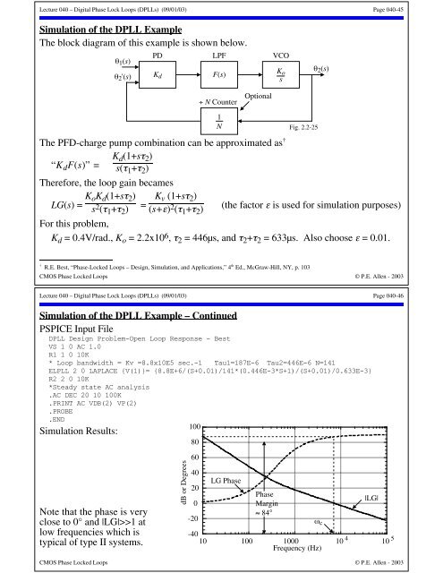
Lecture <strong>040</strong> – Digital Phase Lock Loops (<strong>DPLLs</strong>) (09/01/03) Page <strong>040</strong>-45Simulation of the DPLL ExampleThe block diagram of this example is shown below.θ 1 (s)θ 2 '(s)PDK dLPFF(s)VCOK osθ 2 (s)÷ N CounterOptionalThe PFD-charge pump combination can be approximated as †K d (1+sτ 2 )“K d F(s)” = s(τ 1 +τ 2 )Therefore, the loop gain becamesLG(s) = K oK d (1+sτ 2 )s 2 (τ 1 +τ 2 )=K v (1+sτ 2 )(s+ε) 2 (τ 1 +τ 2 )1NFig. 2.2-25(the factor ε is used for simulation purposes)For this problem,K d = 0.4V/rad., K o = 2.2x10 6 , τ 2 = 446µs, and τ 2 +τ 2 = 633µs. Also choose ε = 0.01.† R.E. Best, “Phase-Locked Loops – Design, Simulation, and Applications,” 4 th Ed., McGraw-Hill, NY, p. 103CMOS Phase Locked Loops © P.E. Allen - 2003Lecture <strong>040</strong> – Digital Phase Lock Loops (<strong>DPLLs</strong>) (09/01/03) Page <strong>040</strong>-46Simulation of the DPLL Example – ContinuedPSPICE Input FileDPLL Design Problem-Open Loop Response - BestVS 1 0 AC 1.0R1 1 0 10K* Loop bandwidth = Kv =8.8x10E5 sec.-1 Tau1=187E-6 Tau2=446E-6 N=141ELPLL 2 0 LAPLACE {V(1)}= {8.8E+6/(S+0.01)/141*(0.446E-3*S+1)/(S+0.01)/0.633E-3}R2 2 0 10K*Steady state AC analysis.AC DEC 20 10 100K.PRINT AC VDB(2) VP(2).PROBE.END100Simulation Results:80Note that the phase is veryclose to 0° and |LG|>>1 atlow frequencies which istypical of type II systems.dB or Degrees6<strong>040</strong>LG Phase20Phase|LG|0Margin≈ 84°-20ω c-4010 100 1000 10 4 10 5Frequency (Hz)CMOS Phase Locked Loops © P.E. Allen - 2003