- Page 7 and 8: CATALOG SERIES INDEXIf a Part Numbe
- Page 9: RDESIGNRECISIONNDUSTRIALOMPONENTSRL
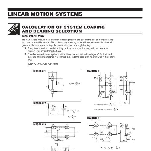
- Page 16 and 17: TECHNICAL SECTIONSystem 10 — Econ
- Page 18 and 19: LINEAR MOTION SYSTEMS WITH INTEGRAL
- Page 20 and 21: POSITIONING STAGESBall or Crossed R
- Page 22 and 23: ROTARY TABLERatios 45:1, 90:1, 180:
- Page 24 and 25: TECHNICAL SECTIONTypical coefficien
- Page 26 and 27: BALL SLIDESCarriage Hole SpacingTot
- Page 28 and 29: ALUMINUM CROSSED ROLLER SLIDESMeasu
- Page 30 and 31: ECONOMY CROSSED ROLLER SLIDES.0001"
- Page 32 and 33: BALL SLIDE GUIDESCompact Designh 1S
- Page 34 and 35: X-XY-XYZ POSITIONERS WITH MICROMETE
- Page 36 and 37: TECHNICAL SECTIONLead Screw Assembl
- Page 38 and 39: TECHNICAL SECTIONAxial Take-Up Mech
- Page 40 and 41: PZ STYLE LEAD SCREW NUTSFor Use Wit
- Page 42 and 43: PV STYLE LEAD SCREW NUTSFor Use Wit
- Page 44 and 45: ACME LEAD SCREW POWER NUTSInch and
- Page 46 and 47: ANR STYLE ADJUSTABLE COMPLIANT NUTS
- Page 48: BEARING HOUSING BLOCKSDiagram 1Mate
- Page 58 and 59: TECHNICAL SECTIONWhatever your appl
- Page 60 and 61:
PRE-DRILLED SHAFTSTYPE D Solid AISI
- Page 62 and 63:
SHAFT SUPPORT BLOCKS / HANGERSClamp
- Page 64 and 65:
RECIRCULATING BALL LINEAR BEARINGSI
- Page 66 and 67:
SELF-ALIGNING BEARINGSInch and Metr
- Page 68 and 69:
PIC CERAMIC COATED LINEAR BEARINGSL
- Page 70 and 71:
METRIC LINEAR BEARING HOUSINGFor Cl
- Page 72 and 73:
NOTES4-16Phone: 800-243-6125 ■ FA
- Page 74 and 75:
TECHNICAL SECTIONApplication Inform
- Page 76 and 77:
NO-SLIP SERIESPIC’s No-Slip and N
- Page 78 and 79:
NO-SLIP POSITIVE DRIVE BELT - ULTRA
- Page 80 and 81:
NO-SLIP POSITIVE DRIVE BELT32DP, .0
- Page 82 and 83:
NO-SLIP POSITIVE DRIVE BELT24 DP .1
- Page 84 and 85:
NO-SLIP POSITIVE DRIVE BELT.1475CP,
- Page 86 and 87:
NO-SLIP POSITIVE DRIVE BELT20DP, .1
- Page 88 and 89:
NO-SLIP POSITIVE DRIVE BELT20DP, .1
- Page 90 and 91:
NO-SLIP POSITIVE DRIVE BELT “CHAI
- Page 92 and 93:
NO-SLIDE TIMING BELTS40 DP (.0816 P
- Page 94 and 95:
NO-SLIDE TIMING BELTS3 /8" Pitch, 1
- Page 96 and 97:
E*P*S DRIVER SYSTEM SELECTION PROCE
- Page 98 and 99:
E*P*S TIMING BELTS.080 Pitch, 1 /8"
- Page 100 and 101:
E*P*S TIMING BELTS40 D.P. (.0816 Pi
- Page 102 and 103:
E*P*S TIMING BELTS1 /5" (.200) Pitc
- Page 104 and 105:
E*P*S TIMING PULLEYS1 /5" (.200) Pi
- Page 106 and 107:
E*P*S HTD ® TIMING BELTS3mm HTD ®
- Page 108 and 109:
E*P*S HTD ® TIMING BELTS5mm HTD ®
- Page 110 and 111:
ROUND BELTS AND PRECISION GROOVED P
- Page 112 and 113:
ROUND BELTS AND PRECISION GROOVED P
- Page 114 and 115:
.1475 PITCH MINIATURE PITCH SPROCKE
- Page 116 and 117:
TECHNICAL SECTIONTo help customers
- Page 118 and 119:
PRECISION BALL BEARINGSABEC 1,3, An
- Page 120 and 121:
SINTERED BRONZE BEARINGSSleeve & Fl
- Page 122 and 123:
NON-METALLIC BEARINGSSleeve & Flang
- Page 124 and 125:
NON-CORROSIVE BALL BEARINGSInch & M
- Page 126 and 127:
ROD ENDSNylon & Phosphor Bronze Rac
- Page 128 and 129:
BEARING HOUSING — 3 /8" , 1 /2" a
- Page 130 and 131:
OUTER RACE SHIM SPACERSMaterial:300
- Page 132 and 133:
LAMINATED BRASS SHIM SPACERSPRECISI
- Page 134 and 135:
ADJUSTABLE HUB CLAMPRef.Gear Bore*N
- Page 136:
PRECISION GROUND SHAFTING — 1 /32
- Page 139 and 140:
PRECISION CASE HARDENED & GROUND SH
- Page 141 and 142:
RDESIGNRECISIONNDUSTRIALOMPONENTSRC
- Page 143 and 144:
FLANGE MOUNTED-POWER OFF BRAKES24 V
- Page 145 and 146:
SLIP CLUTCHES — CONTINUOUS SLIP O
- Page 147 and 148:
ROLLER CLUTCHES■ Ideal for indexi
- Page 149 and 150:
BELLOWS COUPLINGS.12 to 3 /8" Bore
- Page 151 and 152:
MULTI-JAW COUPLINGS — 64 PITCH1 /
- Page 153 and 154:
FLEXIBLE-ZERO BACKLASH COUPLING1 /8
- Page 155 and 156:
PRECISION UNIVERSAL JOINTS1 /8", 3
- Page 157 and 158:
DESIGNRPRECISION HARDWARERRECISIONN
- Page 159 and 160:
SOCKET HEAD SHOULDER SCREWS303 & Ha
- Page 161 and 162:
“SILVER-GRIP” SET SCREWSInch an
- Page 163 and 164:
SET SCREWS — CUP POINTConforming
- Page 165 and 166:
PRECISION WASHERSMachinedC ±.006 A
- Page 167 and 168:
METRIC RETAINING RINGSAll Dimension
- Page 169 and 170:
PRECISION SYNCHRO MOUNTING CLAMPSTa
- Page 171 and 172:
METRIC PRECISION DOWEL PINS — PRE
- Page 173 and 174:
KNURLED THUMB SCREWS#4-40 To 1 /4-2
- Page 175 and 176:
STAINLESS PRECISION SPRINGSCompress
- Page 177 and 178:
HANDLES — CHASSIS5/16min.Material
- Page 179 and 180:
PRECISION ENGRAVED DRUM DIALSClockw
- Page 181 and 182:
PRECISION HAND CRANKS.1248.1873.249
- Page 183 and 184:
RDESIGNRECISIONNDUSTRIALOMPONENTSRM
- Page 185 and 186:
TECHNICAL SECTIONStructural Design
- Page 187 and 188:
MOUNTING COMPONENTSConnecting Angle
- Page 189 and 190:
MOUNTING COMPONENTSAdjustable Joint
- Page 191 and 192:
FASTENING HARDWAREFasteners / T-Slo
- Page 193 and 194:
ACCESSORIESStandard & [MiniatureT-S
- Page 195 and 196:
RDESIGNRECISIONNDUSTRIALOMPONENTSRE
- Page 197 and 198:
PRECISION BREADBOARD KITSPRECISION
- Page 199 and 200:
DESIGNRSPEED REDUCER & GEAR HEADSRR
- Page 201 and 202:
PRECISION GEAR HEADS1 1 /16 " Dia.
- Page 203 and 204:
HELICAL GEAR ASSEMBLIES — 48 PITC
- Page 205 and 206:
GENEVA MECHANISMSIntermittent Motio
- Page 207 and 208:
RDESIGNRECISIONNDUSTRIALOMPONENTSRG
- Page 209 and 210:
TECHNICAL SECTIONTable of Pitch Dia
- Page 211 and 212:
SPUR GEAR-16 PITCH — 3 /16" Face
- Page 213 and 214:
SPUR GEAR-24 PITCH — 1 /8" Face W
- Page 215 and 216:
SPUR GEAR-24 PITCH — 3 /16" Face
- Page 217 and 218:
SPUR GEAR-32 PITCH — 1 /8" Face W
- Page 219 and 220:
SPUR GEAR-32 PITCH — 3 /16" Face
- Page 221 and 222:
SPUR GEAR-48 PITCH — 1 /8" Face W
- Page 223 and 224:
SPUR GEAR-64 PITCH — 1 /8" Face W
- Page 225 and 226:
SPUR GEAR-64 PITCH — 1 /8" Face W
- Page 227 and 228:
SPUR GEAR-72 PITCH — 1 /8" Face W
- Page 229 and 230:
SPUR GEAR-80 PITCH — 1 /8" Face W
- Page 231 and 232:
SPUR GEAR-96 PITCH — 1 /16", 3 /3
- Page 233 and 234:
SPUR GEAR-120 PITCH — 1 /16", 3 /
- Page 235 and 236:
FINE PITCH RACK DATA — 24 to 120
- Page 237 and 238:
DELRIN ® SPUR GEAR-24 PITCH — 3
- Page 239 and 240:
DELRIN ® SPUR GEAR-48 PITCH — 3
- Page 241 and 242:
PRECISION CLUSTER GEARSAGMA 10CLUST
- Page 243 and 244:
ANTI-BACKLASH GEAR-24 PITCH — 3 /
- Page 245 and 246:
ANTI-BACKLASH GEAR-48 PITCH — .10
- Page 247 and 248:
ANTI-BACKLASH GEAR-64 PITCH — .10
- Page 249 and 250:
ANTI-BACKLASH GEAR-72 PITCH — .10
- Page 251 and 252:
HELICAL GEAR-48 NORMAL PITCH 3 /16"
- Page 253 and 254:
ANTI-BACKLASH WORM WHEEL- 48 PITCHS
- Page 255 and 256:
ANTI-BACKLASH WORM WHEEL- 64 PITCH1
- Page 257 and 258:
MITER & BEVEL GEARS- 72 PITCH — 2
- Page 259 and 260:
GEAR BLANKS — NO TEETHPin Hub —
- Page 261 and 262:
SPUR GEARS — 0.3 Module ■3.18mm
- Page 263 and 264:
SPUR GEARS — 0.4 Module ■3.18 a
- Page 265 and 266:
SPUR GEARS — 0.5 Module ■3.18mm
- Page 267 and 268:
SPUR GEARS — 0.5 Module ■3.18mm
- Page 269 and 270:
SPUR GEARS — 0.7 Module ■4.76mm
- Page 271 and 272:
SPUR GEARS — 0.8 Module ■9.52 F
- Page 273 and 274:
GEAR & DIAL HUB-PIN TYPE — 1 /8",
- Page 275 and 276:
RDESIGNRECISIONNDUSTRIALOMPONENTSRT
- Page 277 and 278:
TECHNICAL SECTIONSECTION 2. Basic G
- Page 279 and 280:
TECHNICAL SECTIONSECTION 2. Basic G
- Page 281 and 282:
TECHNICAL SECTIONSECTION 3. Backlas
- Page 283 and 284:
TECHNICAL SECTIONSECTION 5. Toleran
- Page 285 and 286:
TECHNICAL SECTIONSECTION 7. Equival
- Page 287 and 288:
ALPHABETICAL INDEXPRODUCT DESCRIPTI
- Page 289 and 290:
ALPHABETICAL INDEXPRODUCT DESCRIPTI