PIC Design - RBC Bearings
PIC Design - RBC Bearings
PIC Design - RBC Bearings
- No tags were found...

Create successful ePaper yourself
Turn your PDF publications into a flip-book with our unique Google optimized e-Paper software.
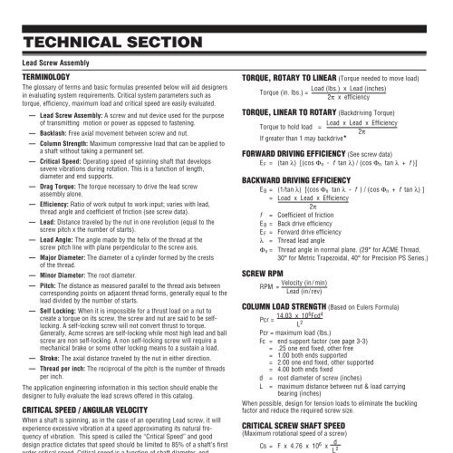
TECHNICAL SECTIONLead Screw AssemblyTERMINOLOGYThe glossary of terms and basic formulas presented below will aid designersin evaluating system requirements. Critical system parameters such astorque, efficiency, maximum load and critical speed are easily evaluated.— Lead Screw Assembly: A screw and nut device used for the purposeof transmitting motion or power as opposed to fastening.— Backlash: Free axial movement between screw and nut.— Column Strength: Maximum compressive load that can be applied toa shaft without taking a permanent set.— Critical Speed: Operating speed of spinning shaft that developssevere vibrations during rotation. This is a function of length,diameter and end supports.— Drag Torque: The torque necessary to drive the lead screwassembly alone.— Efficiency: Ratio of work output to work input; varies with lead,thread angle and coefficient of friction (see screw data).— Lead: Distance traveled by the nut in one revolution (equal to thescrew pitch x the number of starts).— Lead Angle: The angle made by the helix of the thread at thescrew pitch line with plane perpendicular to the screw axis.— Major Diameter: The diameter of a cylinder formed by the crestsof the thread.— Minor Diameter: The root diameter.— Pitch: The distance as measured parallel to the thread axis betweencorresponding points on adjacent thread forms, generally equal to thelead divided by the number of starts.— Self Locking: When it is impossible for a thrust load on a nut tocreate a torque on its screw, the screw and nut are said to be selflocking.A self-locking screw will not convert thrust to torque.Generally, Acme screws are self-locking while most high lead and ballscrew are non self-locking. A non self-locking screw will require amechanical brake or some other locking means to a sustain a load.— Stroke: The axial distance traveled by the nut in either direction.— Thread per inch: The reciprocal of the pitch is the number of threadsper inch.The application engineering information in this section should enable thedesigner to fully evaluate the lead screws offered in this catalog.CRITICAL SPEED / ANGULAR VELOCITYWhen a shaft is spinning, as in the case of an operating Lead screw, it willexperience excessive vibration at a speed approximating its natural frequencyof vibration. This speed is called the “Critical Speed” and gooddesign practice dictates that speed should be limited to 85% of a shaft’s firstorder critical speed. Critical speed is a function of shaft diameter, endsupport configuration and unsupported length. These speeds are shown ingraphic form for various shaft diameters, lengths and supports.COLUMN STRENGTH / COMPRESSION LOADUnder compressive loading a sufficiently slender shaft will fail by elasticinstability at a load well below the shaft’s elastic limit or rated load. A graphis provided to show the maximum safe column load for various diameters,lengths and supports. Shaft slenderness ratios exceeding 200 are notrecommended and the curves are dotted for these ratios. Column strengthlimitations do not apply to shafts under tension loads.3-2Phone: 800-243-6125 ■ FAX: 203-758-8271E-Mail: sales@pic-design.comTORQUE, ROTARY TO LINEAR (Torque needed to move load)DESIGN®Torque (in. lbs.) =Load (lbs.) x Lead (inches)2π x efficiencyTORQUE, LINEAR TO ROTARY (Backdriving Torque)Load x Lead x EfficiencyTorque to hold load =2πIf greater than 1 may backdrive*FORWARD DRIVING EFFICIENCY (See screw data)E F = (tan λ) [(cos Φ n - f tan λ) / (cos Φ n tan λ + f )]BACKWARD DRIVING EFFICIENCYE B = (1/tan λ) [(cos Φ n tan λ - f ) / (cos Φ n + f tan λ) ]= Load x Lead x Efficiency2πf = Coefficient of frictionE B = Back drive efficiencyE F = Forward drive efficiencyλ = Thread lead angleΦ n = Thread angle in normal plane. (29° for ACME Thread,30° for Metric Trapezoidal, 40° for Precision PS Series.)SCREW RPMVelocity (in/min)RPM =Lead (in/ rev)COLUMN LOAD STRENGTH (Based on Eulers Formula)Pcr = 14.03 x 10⁶ Fcd 4L 2Pcr = maximum load (lbs.)Fc = end support factor (see page 3-3)= .25 one end fixed, other free= 1.00 both ends supported= 2.00 one end fixed, other supported= 4.00 both ends fixedd = root diameter of screw (inches)L = maximum distance between nut & load carryingbearing (inches)When possible, design for tension loads to eliminate the bucklingfactor and reduce the required screw size.CRITICAL SCREW SHAFT SPEED(Maximum rotational speed of a screw)Cs = F x 4.76 x 10 6 x d L 2Cs = Critical speed (RPM)d = root diameter of screw (inches)L = Length between supports (inches)F = end support factor (see page 3-3).36 one end fixed, other free1.00 simple supports both ends1.47 one end fixed, one simple2.23 both ends fixedCritical shaft speed should be reduced to 85% to allow for otherfactors such as alignment and straightness.*If the lead is greater than 1/3 of the diameter, it may backdrivewww.pic-design.comInteractive catalog ■ CAD ■ e-commerce