PIC Design - RBC Bearings
PIC Design - RBC Bearings
PIC Design - RBC Bearings
- No tags were found...

You also want an ePaper? Increase the reach of your titles
YUMPU automatically turns print PDFs into web optimized ePapers that Google loves.
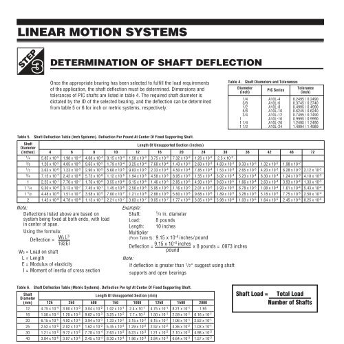
LINEAR MOTION SYSTEMSSTEPDETERMINATION OF SHAFT DEFLECTIONOnce the appropriate bearing has been selected to fulfill the load requirementsof the application, the shaft deflection must be determined. Dimensions andtolerances of <strong>PIC</strong> shafts are listed in table 4. The required shaft diameter isdictated by the ID of the selected bearing, and the deflection can be determinedfrom table 5 or 6 for inch or metric systems, respectively.Table 4. Shaft Diameters and TolerancesDiameter<strong>PIC</strong> SeriesTolerance(inch)(inch).1/4 A10L-4 0.2495 / 0.2490.3/8 A10L-6 0.3745 / 0.3740.1/2 A10L-8 0.4995 / 0.4990.5/8 A10L-10 0.6245 / 0.6240.3/4 A10L-12 0.7495 / 0.74901. A10L-16 0.9995 / 0.99901.1/4 A10L-20 1.2495 / 1.24901.1/2 A10L-24 1.4994 / 1.4989Table 5. Shaft Deflection Table (Inch Systems). Deflection Per Pound At Center Of Fixed Supporting Shaft.ShaftLength Of Unsupported Section (inches)Diameter(inches) 4 6 8 10 12 16 20 24 30 36 42 48 721 /4 5.85 x 10 -5 1.98 x 10 -4 4.68 x 10 -4 9.15 x 10 -4 1.58 x 10 -3 3.75 x 10 -3 7.32 x 10 -3 1.26 x 10 -2 2.5 x 10 -23 /8 1.20 x 10 -5 4.05 x 10 -5 9.63 x 10 -5 1.79 x 10 -4 3.25 x 10 -4 7.68 x 10 -4 1.43 x 10 -3 2.60 x 10 -3 4.83 x 10 -3 8.33 x 10 -3 1.32 x 10 -2 1.98 x 10 -21 /2 3.63 x 10 -6 1.23 x 10 -5 2.90 x 10 -5 5.68 x 10 -5 9.83 x 10 -5 2.33 x 10 -4 4.50 x 10 -4 7.85 x 10 -4 1.53 x 10 -3 2.65 x 10 -3 4.20 x 10 -3 6.28 x 10 -3 2.12 x 10 -23 /4 7.15 x 10 -7 2.42 x 10 -6 5.73 x 10 -6 1.12 x 10 -5 1.94 x 10 -5 4.58 x 10 -5 8.95 x 10 -5 1.55 x 10 -4 3.02 x 10 -4 5.23 x 10 -4 8.30 x 10 -4 1.24 x 10 -3 4.18 x 10 -31 2.25 x 10 -7 7.70 x 10 -7 1.76 x 10 -6 3.55 x 10 -6 6.15 x 10 -6 1.46 x 10 -5 2.85 x 10 -5 4.93 x 10 -5 9.63 x 10 -5 1.66 x 10 -4 2.63 x 10 -4 3.93 x 10 -4 1.33 x 10 -31 1 /4 9.30 x 10 -8 3.13 x 10 -7 7.45 x 10 -7 1.45 x 10 -6 2.50 x 10 -6 5.95 x 10 -6 1.16 x 10 -5 2.01 x 10 -5 3.93 x 10 -5 6.78 x 10 -5 1.08 x 10 -4 1.61 x 10 -4 5.43 x 10 -41 1 /2 4.48 x 10 -8 1.51 x 10 -7 3.58 x 10 -5 7.00 x 10 -7 1.21 x 10 -6 2.88 x 10 -6 5.60 x 10 -6 9.68 x 10 -6 1.89 x 10 -5 3.28 x 10 -5 5.18 x 10 -5 7.75 x 10 -5 2.58 x 10 -42 1.42 x 10 -8 4.78 x 10 -8 1.13 x 10 -7 2.21 x 10 -7 3.83 x 10 -7 9.05 x 10 -7 1.77 x 10 -6 3.05 x 10 -6 5.98 x 10 -6 1.03 x 10 -5 1.64 x 10 -5 2.45 x 10 -5 8.25 x 10 -5Note:Deflections listed above are based onsystem being fixed at both ends, with loadin center of span.Using the formula:Ws L3Deflection =192EIWs = Load on shaftL = LengthE = Modulus of elasticityI = Moment of inertia of cross sectionExample:Shaft: 1 /4 in. diameterLoad: 8 poundsLength: 10 inchesMultiplier(From Table 5): 9.15 x 10 -4 inches/ poundDeflection = 9.15 x 10⁻⁴ inches x 8 pounds = .0073 inchespoundNote:If deflection is greater than 1 /2° suggest using shaftsupports and open bearingsTable 6. Shaft Deflection Table (Metric Systems). Deflection Per kgf At Center Of Fixed Supporting Shaft.ShaftLength Of Unsupported Section (mm)Diameter(mm) 125 250 500 750 1000 1250 1500 200012 4.75 x 10 -4 3.80 x 10 -3 3.04 x 10 -2 1.02 x 10 -1 2.4 x 10 -1 4.75 x 10 -1 8.21 x 10 -1 1.9516 1.50 x 10 -4 1.20 x 10 -3 9.62 x 10 -3 3.25 x 10 -2 7.7 x 10 -2 1.50 x 10 -1 2.59 x 10 -1 6.16 x 10 -120 6.15 x 10 -5 4.92 x 10 -4 3.94 x 10 -3 1.33 x 10 -2 3.15 x 10 -2 6.15 x 10 -2 1.06 x 10 -1 2.52 x 10 -125 2.52 x 10 -5 2.02 x 10 -4 1.62 x 10 -3 5.45 x 10 -3 1.29 x 10 -2 2.52 x 10 -2 4.36 x 10 -2 1.03 x 10 -130 1.21 x 10 -5 9.72 x 10 -5 7.78 x 10 -4 2.63 x 10 -3 6.23 x 10 -3 1.21 x 10 -2 2.10 x 10 -2 4.98 x 10 -240 3.84 x 10 -6 3.07 x 10 -5 2.45 x 10 -4 8.30 x 10 -4 1.96 x 10 -3 3.84 x 10 -3 6.64 x 10 -3 1.57 x 10 -2Note:Deflections listed above are based onsystem being fixed at both ends, withload in center of span.Using the formula:Ws L3Deflection =192EIWs = Load on shaftL = LengthE = Modulus of elasticityI = Moment of inertia of cross sectionExample:Shaft: 20 mm diameterLoad: 25 kgfLength: 1000 mmMultiplier(From Table 6): 3.15 x 10 -2 mm / kgDeflection = 3.15 x 10-2 mm x 25 kgf = 0.7875 mmkgfShaft Load = Total LoadNumber of Shafts1-4Phone: 800-243-6125 ■ FAX: 203-758-8271E-Mail: sales@pic-design.comDESIGN®www.pic-design.comInteractive catalog ■ CAD ■ e-commerce