PIC Design - RBC Bearings
PIC Design - RBC Bearings
PIC Design - RBC Bearings
- No tags were found...

You also want an ePaper? Increase the reach of your titles
YUMPU automatically turns print PDFs into web optimized ePapers that Google loves.
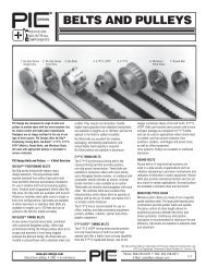
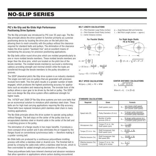
NO-SLIP SERIES<strong>PIC</strong>’s No-Slip and No-Slide High PerformancePositioning Drive SystemsThe No-Slip principle was introduced by <strong>PIC</strong> over 25 years ago. The No-Slip principle allows the drive system to function primarily as a precisepositioning device by locating the drive pins on the belt pitch line,allowing them to mesh smoothly with the pulleys without the clearancerequired for standard belts and pulleys. The elimination of the clearancemakes the drive system “backlash free” and an excellent means ofmaintaining the accuracy for precision positioning applications.No-Slip belts utilize round drive pins which are molded perpendicularly toone or more molded tensile members. These molded tensile members arelarger than the drive pins, which are located on the pitch line of thetensile member. The molded tensile member(s) surround a reinforcingcable(s) providing strength and minimal stretch while the loads aretransferred through the tensile members to the pulley shoulders orgrooves.The 32DP (diametral pitch) No-Slip drive system is an industry standard.The single core belt runs on pulleys that are generated with precisioninvolute form teeth. This fine pitch results in a greater number of teethengaged, which produces the highest positioning accuracy for applicationssuch as encoders and measuring devices. The involute form of thepulleys allows a spur gear to be driven by the belt or pulley. The 32DPtwin core design No-Slip drive system offers additional strength forhigher loads.The .1475CP and .2500 CP No-Slip drive systems are twin core belts thatare an economical solution to miniature pitch stainless steel chain. Thesebelts are for high load carrying applications requiring No-Slip accuracy.These belts have replaced miniature pitch stainless steel chain in manyexisting applications.The No-Slide principle allows the drive system to operate using pulleyswithout flanges. The belt stays on the center of the pulley due to anencapsulated stainless steel or Aramid cable in the center of the belt anda matching groove in the pulley.The elimination of a flange results in two major benefits. It produces amore compact drive system and it also eliminates the air trapped by theflanges found on conventional synchronous belts — therefore making ita quieter running belt.No-Slide belts are produced by a continuous polyurethane moldingprocess with either a stainless steel or Aramid core. The finished belt isjoined by crimping the cable ends within a stainless steel ferrule, which isthen overmolded for added strength and protection of the pulley.These polyurethane belts have inherent chemical and abrasion resistancethat allow operation in applications where carbon dusting encounteredwith neoprene belts cannot be tolerated. The No-Slide series of belts areexcellent for medical and packaging applications.BELT LENGTH CALCULATIONSD = Pitch Diameter Large Pulley (inches)d = Pitch Diameter Small Pulley (inches)C = Center Distance (inches)α = sin[ D-d 2C ]-1BELT SPEED CALCULATIONSBS(fpm) = (.262) x PD x RPMSTANDARD CALCULATIONSα = Angle Between Belt and CenterlineL = Belt Pitch Length (inches — approx.)L = π (D + d) + 4C 2 +D 2 +d 22CENTER DISTANCE CALCULATIONSC = K + K2 - 32 (D-d) 216Where K = 4L - 2 π (D+d)Required Given FormulaShaft speeds (rpm) R =Speed ratio (R) Pulley Diameters (D & d) R =Horsepower (hp)For Parallel Shafts:L = 2C Cos α + π (D+d) πα (D-d)+2 180orL APPROX = 2C + 1.57(D+d) + (D-d)24CTorque (T) in in.- lbs.Effective tension (Te)Number of pulleygrooves (N & n)R =Torque (T) in in.- lbs.hp = T x rpmShaft speed (rpm) 63,025Shaft horsepower (hp)Shaft speed (rpm)Shaft horsepower (hp)Belt speed (BS)For Right Angle ShaftsFA & FS Only:T =rpm (faster shaft speed)rpm (slower shaft speed)D (larger pulley diameter)d (smaller pulley diameter)N (larger pulley groove no.)n (smaller pulley groove no.)63,025 x hprpm33,000 x hpTe =BSEffective tension (Te) Torque (T) in in.- lbs.Te = 2 x Tin pounds Pulley pd in inches pdThe design guide (shown on previous page) enables users to select theappropriate system for a particular application. The belt length calculationsare included to insure that the proper belt length has been selectedfor the center distance and ratio of your drive system.5-4Phone: 800-243-6125 ■ FAX: 203-758-8271E-Mail: sales@pic-design.comDESIGN®www.pic-design.comInteractive catalog ■ CAD ■ e-commerce