PIC Design - RBC Bearings
PIC Design - RBC Bearings
PIC Design - RBC Bearings
- No tags were found...

Create successful ePaper yourself
Turn your PDF publications into a flip-book with our unique Google optimized e-Paper software.
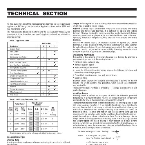
TECHNICAL SECTIONTo help customers select the most appropriate bearings for use in particularapplications, <strong>PIC</strong> <strong>Design</strong> has included an Application Guide and an ABEC andISO Tolerancing Chart.The Application Guide assists in determining the bearing quality necessary foryour system. If you do not find your specific applications listed, use ones whichare most similar.Table 1. Application GuideABEC GradeApplication 1 3 5 7Electric Motors✔Tape Guides✔Gyro Gimbals✔Commercial Gear Trains ✔ ✔Precision Gear Trains ✔ ✔AGMA Q14 Gear Trains✔Very High Speed Applications✔Timing Pulley Supports ✔ ✔“No-Slip” Pulley Systems ✔ ✔Chain Drive Systems✔Bread Board Experiments✔Computer Disk Drive✔Laser Aligning Equipment ✔ ✔Hand Adjusted Settings✔Robotics ✔ ✔Encoder Applications ✔ ✔Office Equipment ✔ ✔Print Heads ✔ ✔Table 2. ABEC & ISO Tolerancing ChartMean DiameterRadial RunoutToleranceABEC Inner Outer ISOBore O.D. O.D. SizeGrade Ring RingClass1 .0003 .00053 .0003 .00045 .00015 .00026-2+.0000 +.00000-18 mm0-.0003 -.0003 (Normal)+.0000 +.0000-.0002 -.0003+.0000 +.0000-.0002 -.00020-30 mm 60-30 mm 57 .0001 .00015+.0000 +.00000-30 mm 4-.0002 -.0002This information is intended for reference only. All dimensions are in inches.BEARING SELECTION:Bearing SizeA variety of criteria may have an influence on bearing size selection for differentinstallations:Mating parts. One or more of the bearing dimensions may be governed by thesize of a mating part (e.g. shaft, housing).Capacity. Bearing loading, dynamic and static, will establish minimum capacityrequirements and influence size selection because capacity generally increaseswith size.Speedability. Smaller bearings can usually operate at higher speeds than largebearings, hence the speed requirement of an application may affect sizeselection.Stiffness. Large bearings yield less than small bearings and are the betterchoice where bearing stiffness is crucial.Weight. In some cases, bearing weight may have to be considered and factoredinto the selection process.Phone: 800-243-6125 ■ FAX: 203-758-8271E-Mail: sales@pic-design.comTorque. Reducing the ball size and using wider raceway curvatures are tacticswhich may be used to reduce torque.AISI 440 stainless steel is the standard material for miniature and instrumentbearings and torque tube bearings. It is optional for spindle and turbinebearings. This is a hardenable, corrosion-resistant steel with adequate fatigueresistance, good load-carrying capacity, excellent stability and wear resistance.Operating temperature range is -400 o F to 300 o F for miniature and instrumentbearings.SAE 52100 chrome steel is the standard material for spindle and turbinebearings. It is also available in many miniature and instrument sizes, and maybe preferable when fatigue life and static capacity are critical. This material hasexcellent capacity, fatigue resistance and stability. Operating temperature limitis 400 o F when used in spindle and turbine bearings.Preloading TechniquesPreloading is the removal of internal clearance in a bearing by applying apermanent thrust load to it. Preloading is used to:● Eliminate radial and axial play● Increase system rigidity● Reduce nonrepetitive runout● Lessen the difference in contact angles between the balls and both inner andouter rings at very high speeds● Prevent ball skidding under very high accelerations● Suppress noise<strong>Bearings</strong> should be preloaded as lightly as is necessary to achieve the desiredresults. This avoids excessive heat generation, which reduces speed capabilityand bearing life.There are three basic methods of preloading — springs, axial adjustment andduplex bearings.Limiting SpeedsLimiting speed is defined as the speed at which the internally generatedtemperature in a mounted bearing reaches the lowest maximum temperaturepermissible for any of its components, including the lubricant.There are many factors which combine to determine the limiting speeds of balland roller bearings. Therefore it is not possible to calculate these speeds withaccuracy. Frequently it is necessary to estimate the speed limit of a bearing onthe basis of experience with bearings operating under conditions similar tothose in question. For small and medium size bearings of the same type anddimension series, operating under similar conditions, the speed limit is approximatelyinversely proportional to the bearing bore. For large bearings this nolonger applies as their speed limits are relatively lower. A bearing of light sectionhas a higher speed limit than a bearing of heavy section. As a result a moregeneral comparison can be made between speeds of different radial bearings byusing the bearing mean diameter dm as a reference instead of the bore d. Fromthe above, the following formulas are derived:For Radial and Angular Contact <strong>Bearings</strong>. N= Ad mWhere: N = The speed Limit, RPMd + Ddm = The Bearing, mean diameter =2d = The bearing bore in mmD = The bearing O.D., mmA = A value Single Row Ball: 400,000Single Row Angular Contact:Low Contact Angle: 800,000High Contact Angle: 500,000The above values for A are useful as a quick orientation regarding speed limitsfor different bearing types and sizes operating under a moderate load andotherwise favorable conditions.The speed limits calculated using these formulas and values of A should beconsidered a maximum. These values apply only to bearings lubricated with oil.When bearings are lubricated with grease, use 70% of the above for A.DESIGN®www.pic-design.comInteractive catalog ■ CAD ■ e-commerce