DH-10 Heads & Controls OPERATOR'S MANUAL ... - Lincoln Electric
DH-10 Heads & Controls OPERATOR'S MANUAL ... - Lincoln Electric
DH-10 Heads & Controls OPERATOR'S MANUAL ... - Lincoln Electric
Create successful ePaper yourself
Turn your PDF publications into a flip-book with our unique Google optimized e-Paper software.
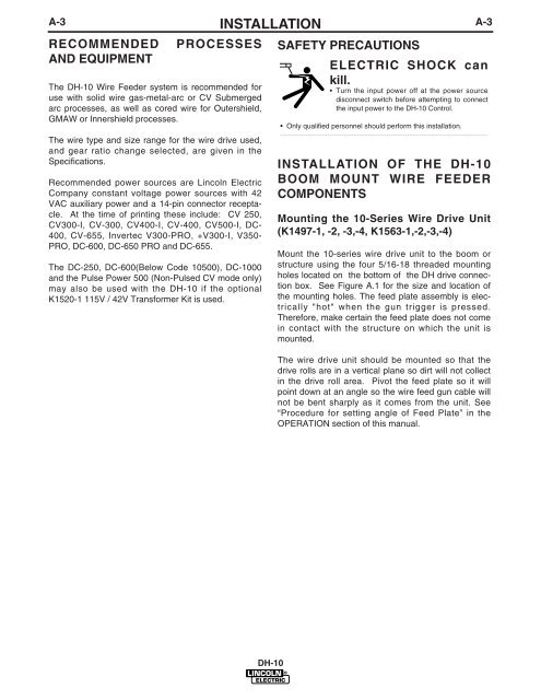
A-3RECOMMENDEDAND EQUIPMENTPROCESSESThe <strong>DH</strong>-<strong>10</strong> Wire Feeder system is recommended foruse with solid wire gas-metal-arc or CV Submergedarc processes, as well as cored wire for Outershield,GMAW or Innershield processes.The wire type and size range for the wire drive used,and gear ratio change selected, are given in theSpecifications.Recommended power sources are <strong>Lincoln</strong> <strong>Electric</strong>Company constant voltage power sources with 42VAC auxiliary power and a 14-pin connector receptacle.At the time of printing these include: CV 250,CV300-I, CV-300, CV400-I, CV-400, CV500-I, DC-400, CV-655, Invertec V300-PRO, +V300-I, V350-PRO, DC-600, DC-650 PRO and DC-655.The DC-250, DC-600(Below Code <strong>10</strong>500), DC-<strong>10</strong>00and the Pulse Power 500 (Non-Pulsed CV mode only)may also be used with the <strong>DH</strong>-<strong>10</strong> if the optionalK1520-1 115V / 42V Transformer Kit is used.INSTALLATIONSAFETY PRECAUTIONSA-3ELECTRIC SHOCK cankill.• Turn the input power off at the power sourcedisconnect switch before attempting to connectthe input power to the <strong>DH</strong>-<strong>10</strong> Control.• Only qualified personnel should perform this installation.----------------------------------------------------------------------------------------INSTALLATION OF THE <strong>DH</strong>-<strong>10</strong>BOOM MOUNT WIRE FEEDERCOMPONENTSMounting the <strong>10</strong>-Series Wire Drive Unit(K1497-1, -2, -3,-4, K1563-1,-2,-3,-4)Mount the <strong>10</strong>-series wire drive unit to the boom orstructure using the four 5/16-18 threaded mountingholes located on the bottom of the <strong>DH</strong> drive connectionbox. See Figure A.1 for the size and location ofthe mounting holes. The feed plate assembly is electrically"hot" when the gun trigger is pressed.Therefore, make certain the feed plate does not comein contact with the structure on which the unit ismounted.The wire drive unit should be mounted so that thedrive rolls are in a vertical plane so dirt will not collectin the drive roll area. Pivot the feed plate so it willpoint down at an angle so the wire feed gun cable willnot be bent sharply as it comes from the unit. See“Procedure for setting angle of Feed Plate” in theOPERATION section of this manual.<strong>DH</strong>-<strong>10</strong>


