5000 Series Indicators Instruction Manual - Scale Manuals
5000 Series Indicators Instruction Manual - Scale Manuals
5000 Series Indicators Instruction Manual - Scale Manuals

You also want an ePaper? Increase the reach of your titles
YUMPU automatically turns print PDFs into web optimized ePapers that Google loves.
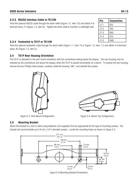
<strong>5000</strong> <strong>Series</strong> <strong>Indicators</strong>EN-132.3.3 RS232 Interface Cable to T51XWPin ConnectionPass the optional RS232 cable through the strain relief (Figure 1-2, item 10) and attach it toJ7-1 RTSterminal block J7 (Figure 1-3, item 6). Tighten the strain relief to maintain a watertight seal.J7-2 TXDJ7-3 RXDJ7-4 CTS2.3.4 Footswitch to T51P or T51XWJ7-5 GNDPass the optional footswitch cable through the strain relief (Figure 1-1, item 15 or Figure 1-2, item 11) and attach it to terminalblock J9 (Figure 1-3, item 5).2.4 T51P Rear Housing OrientationThe T51P is delivered in the wall mount orientation with the connections exiting below the display. The rear housing may bereversed so the connections exit above the display when the T51P is placed horizontally on a bench. To reverse the rear housing,remove the four Phillips head screws, carefully rotate the housing 180°, and reinstall the screws.Figure 2-3. Wall Mount Configuration.Figure 2-4. Bench Top Configuration.2.5 Mounting BracketAttach the bracket to a wall or table using fasteners (not supplied) that are appropriate for the type of mounting surface. Thebracket will accommodate up to 6 mm (1/4”) diameter screws. Locate the mounting holes as shown in Figure 2-5.Figure 2-5 Mounting Bracket Dimensions.