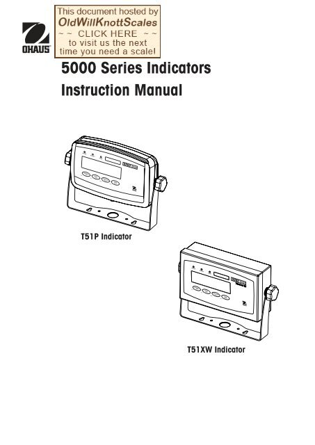
5000 Series Indicators Instruction Manual - Scale Manuals
5000 Series Indicators Instruction Manual - Scale Manuals
5000 Series Indicators Instruction Manual - Scale Manuals

Create successful ePaper yourself
Turn your PDF publications into a flip-book with our unique Google optimized e-Paper software.
<strong>5000</strong> <strong>Series</strong> <strong>Indicators</strong><strong>Instruction</strong> <strong>Manual</strong>T51P IndicatorT51XW Indicatori
<strong>5000</strong> <strong>Series</strong> <strong>Indicators</strong>EN-1TABLE OF CONTENTS1. INTRODUCTION ..........................................................................................................................................EN-51.1 Safety Precautions .....................................................................................................................................EN-51.1.1 Relay Option Safety Precautions ........................................................................................................EN-51.2 Overview of Parts and Controls ...................................................................................................................EN-61.3 Control Functions .....................................................................................................................................EN-102. INSTALLATION .........................................................................................................................................EN-112.1 Unpacking ..............................................................................................................................................EN-112.2 External Connections ................................................................................................................................EN-112.2.1 <strong>Scale</strong> Base with Connector to T51P .................................................................................................EN-112.2.2 RS232 Interface Cable to T51P........................................................................................................EN-112.2.3 AC Power to T51P ........................................................................................................................EN-112.2.4 AC Power to T51XW .......................................................................................................................EN-112.2.5 Battery Power to T51P ....................................................................................................................EN-112.2.6 Mounting Bracket ...........................................................................................................................EN-122.3 Internal Connections .................................................................................................................................EN-122.3.1 Opening the Housing .......................................................................................................................EN-122.3.2 <strong>Scale</strong> Base Without Connector to T51P or T51XW ............................................................................EN-122.3.3 RS232 Interface Cable to T51XW ......................................................................................................EN-132.3.4 Footswitch to T51P or T51XW ..........................................................................................................EN-132.4 T51P Rear Housing Orientation .................................................................................................................EN-132.5 Mounting Bracket .....................................................................................................................................EN-133. SETTINGS ................................................................................................................................................EN-143.1 Menu Structure ........................................................................................................................................EN-143.2 Menu Navigation .....................................................................................................................................EN-153.3 Calibration Menu .....................................................................................................................................EN-153.3.1 Zero Calibration ............................................................................................................................EN-163.3.2 Span Calibration ...........................................................................................................................EN-163.3.3 Linearity Calibration ......................................................................................................................EN-173.3.4 Calibration Test ............................................................................................................................EN-183.3.5 Geographical Adjustment Factor .....................................................................................................EN-183.3.6 End Calibration .............................................................................................................................EN-183.4 Setup Menu .............................................................................................................................................EN-203.4.1 Reset ...........................................................................................................................................EN-203.4.2 Range .........................................................................................................................................EN-203.4.3 Capacity ......................................................................................................................................EN-203.4.4 Graduation ...................................................................................................................................EN-213.4.5 Power On Unit ..............................................................................................................................EN-213.4.6 Zero Range ..................................................................................................................................EN-213.4.7 Auto-Tare .....................................................................................................................................EN-223.4.8 Retain Weight Data .......................................................................................................................EN-223.4.9 Legal for Trade .............................................................................................................................EN-223.4.10 Beeper Volume .............................................................................................................................EN-23
EN-2<strong>5000</strong> <strong>Series</strong> <strong>Indicators</strong>TABLE OF CONTENTS (Cont.)3.4.11 Beeper Signal ...............................................................................................................................EN-233.4.12 Button Beeper ...............................................................................................................................EN-233.4.13 End Setup ....................................................................................................................................EN-233.5 Readout Menu .........................................................................................................................................EN-233.5.1 Reset ...........................................................................................................................................EN-243.5.2 Stable Range ................................................................................................................................EN-243.5.3 Filter ............................................................................................................................................EN-243.5.4 Auto-Zero Tracking ........................................................................................................................EN-243.5.5 Backlight .....................................................................................................................................EN-253.5.6 Auto Off Timer ..............................................................................................................................EN-253.5.7 Gross Indicator ..............................................................................................................................EN-253.5.8 End Readout .................................................................................................................................EN-253.6 Mode Menu .............................................................................................................................................EN-253.6.1 Reset ...........................................................................................................................................EN-263.6.2 Weighing Mode ............................................................................................................................EN-263.6.3 Parts Counting Mode .....................................................................................................................EN-263.6.4 Parts Counting Optimize ................................................................................................................EN-263.6.5 Percent Weighing Mode .................................................................................................................EN-263.6.6 Dynamic Weighing Mode...............................................................................................................EN-263.6.7 Check Weighing Mode...................................................................................................................EN-273.6.8 End Mode ....................................................................................................................................EN-273.7 Unit Menu ...............................................................................................................................................EN-273.7.1 Reset ...........................................................................................................................................EN-273.7.2 Kilogram Unit ...............................................................................................................................EN-273.7.3 Pound Unit ...................................................................................................................................EN-273.7.4 Gram Unit ....................................................................................................................................EN-283.7.5 Ounce Unit ...................................................................................................................................EN-283.7.6 Pound Ounce Unit .........................................................................................................................EN-283.7.7 Tonnes Unit ..................................................................................................................................EN-283.7.8 Custom Unit .................................................................................................................................EN-283.7.9 End Unit ......................................................................................................................................EN-293.8 GMP Menu ..............................................................................................................................................EN-293.8.1 Reset ...........................................................................................................................................EN-293.8.2 Date Type ....................................................................................................................................EN-293.8.3 Date Set .......................................................................................................................................EN-303.8.4 Time Type ....................................................................................................................................EN-303.8.5 Time Set ......................................................................................................................................EN-303.8.6 User ID ........................................................................................................................................EN-313.8.7 Project ID .....................................................................................................................................EN-313.8.8 <strong>Scale</strong> ID .......................................................................................................................................EN-313.8.7 End GMP .....................................................................................................................................EN-313.9 Print1 and Print2 Menus ...........................................................................................................................EN-323.9.1 Reset ...........................................................................................................................................EN-323.9.2 Print Stable data Only ....................................................................................................................EN-323.9.3 Auto Print .....................................................................................................................................EN-323.9.4 Print Content Sub-menu .................................................................................................................EN-33
<strong>5000</strong> <strong>Series</strong> <strong>Indicators</strong>EN-3TABLE OF CONTENTS (Cont.)3.9.5 Layout Sub-menu .........................................................................................................................EN-353.9.6 List Menu Settings .........................................................................................................................EN-353.9.7 End Print1 or End Print2 ................................................................................................................EN-353.10 COM1 and COM2 Menus .........................................................................................................................EN-353.10.1 Reset ...........................................................................................................................................EN-353.10.2 Baud ...........................................................................................................................................EN-363.10.3 Parity ..........................................................................................................................................EN-363.10.4 Stop Bit ........................................................................................................................................EN-363.10.5 Handshake ..................................................................................................................................EN-363.10.6 Address .......................................................................................................................................EN-363.10.7 Alternate Command Sub-menu .......................................................................................................EN-373.10.8 End COM1 or End COM2 ...............................................................................................................EN-373.11 I-O Menu ................................................................................................................................................EN-373.11.1 Reset ...........................................................................................................................................EN-373.11.2 External Input ...............................................................................................................................EN-383.11.3 Input Beep ...................................................................................................................................EN-383.11.4 Relay Output ................................................................................................................................EN-383.11.5 End I-O ........................................................................................................................................EN-393.12 Menu Lock Menu ...................................................................................................................................EN-393.12.1 Reset ...........................................................................................................................................EN-393.12.2 Lock Calibration ...........................................................................................................................EN-393.12.3 Lock Setup ...................................................................................................................................EN-403.12.4 Lock Readout ...............................................................................................................................EN-403.12.5 Lock Mode ...................................................................................................................................EN-403.12.6 Lock Unit .....................................................................................................................................EN-403.12.7 Lock Print1 ..................................................................................................................................EN-403.12.8 Lock Print2 ..................................................................................................................................EN-403.12.9 Lock COM1 ..................................................................................................................................EN-403.12.10 Lock COM2 ................................................................................................................................EN-403.12.11 Lock GMP ..................................................................................................................................EN-413.12.12 Lock I-O .....................................................................................................................................EN-413.12.13 End Lock ...................................................................................................................................EN-413.13 Key Lock Menu .......................................................................................................................................EN-413.13.1 Reset ...........................................................................................................................................EN-413.13.2 Lock All Buttons ............................................................................................................................EN-413.13.3 Lock Off Button .............................................................................................................................EN-413.13.4 Lock Zero Button ...........................................................................................................................EN-413.13.5 Lock Print Button ..........................................................................................................................EN-423.13.6 Lock Unit Button ...........................................................................................................................EN-423.13.7 Lock Function Button .....................................................................................................................EN-423.13.8 Lock Mode Button .........................................................................................................................EN-423.13.9 Lock Tare Button ...........................................................................................................................EN-423.13.10 Lock Menu Button .......................................................................................................................EN-423.13.11 End Lock ...................................................................................................................................EN-423.14 Security Switch .......................................................................................................................................EN-42
EN-4<strong>5000</strong> <strong>Series</strong> <strong>Indicators</strong>TABLE OF CONTENTS (Cont.)4. OPERATION .............................................................................................................................................EN-434.1 Turning Indicator On/Off ............................................................................................................................EN-434.2 Zero Operation .........................................................................................................................................EN-434.3 <strong>Manual</strong> Tare ............................................................................................................................................EN-434.4 Pre-Set Tare ............................................................................................................................................EN-434.5 Auto-Tare ................................................................................................................................................EN-434.6 Changing Units of Measure .......................................................................................................................EN-444.7 Printing Data ...........................................................................................................................................EN-444.8 Application Modes ...................................................................................................................................EN-444.8.1 Weighing .....................................................................................................................................EN-444.8.2 Parts Counting .............................................................................................................................EN-444.8.3 Percent Weighing .........................................................................................................................EN-454.8.4 Check Weighing ...........................................................................................................................EN-464.8.5 Dynamic Weighing .......................................................................................................................EN-475. SERIAL COMMUNICATION ..........................................................................................................................EN-485.1 Interface Commands ................................................................................................................................EN-485.2 Output Format .........................................................................................................................................EN-495.3 Printouts .................................................................................................................................................EN-496. LEGAL FOR TRADE ...................................................................................................................................EN-516.1 Settings ..................................................................................................................................................EN-516.2 Verification ..............................................................................................................................................EN-516.3 Sealing ...................................................................................................................................................EN-517. MAINTENANCE .........................................................................................................................................EN-537.1 Model T51P Cleaning ...............................................................................................................................EN-537.2 Model T51XW Cleaning ............................................................................................................................EN-537.3 Troubleshooting .......................................................................................................................................EN-537.4 Service Information ..................................................................................................................................EN-548. TECHNICAL DATA .....................................................................................................................................EN-558.1 Specifications ..........................................................................................................................................EN-558.2 Accessories and Options ...........................................................................................................................EN-568.3 Drawings and Dimensions ........................................................................................................................EN-578.4 Compliance.............................................................................................................................................EN-58
<strong>5000</strong> <strong>Series</strong> <strong>Indicators</strong>EN-51. INTRODUCTIONThis manual contains installation, operation and maintenance instructions for the T51P and T51XW <strong>Indicators</strong>. Please read thismanual completely before installation and operation.1.1 Safety PrecautionsFor safe and dependable operation of this equipment, please comply with the following safety precautions:• Verify that the input voltage range printed on the data label matches the local AC power to be used.• Make sure that the power cord does not pose a potential obstacle or tripping hazard.• Use only approved accessories and peripherals.• Operate the equipment only under ambient conditions specified in these instructions.• Disconnect the equipment from the power supply when cleaning.• Do not operate the equipment in hazardous or unstable environments.• Do not immerse the equipment in water or other liquids.• Service should only be performed by authorized personnel.• The T51XW is supplied with a grounded power cable. Use only with a compatible grounded power outlet.1.1.1 Relay Option Safety PrecautionsThis equipment may have an optional AC or DC Relay Option board installed. This option allows external devices to becontrolled by the Indicator.CAUTION: ELECTRICAL SHOCK HAZARD. REMOVE ALL POWER CONNECTIONS TO THE INDICATORBEFORE SERVICING OR MAKING INTERNAL CONNECTIONS. THE HOUSING SHOULD ONLY BE OPENED BYAUTHORIZED AND QUALIFIED PERSONNEL, SUCH AS AN ELECTRICAL TECHNICIAN.Before making connections to the Relay terminals, remove power from the system. If the system contains an optionalrechargeable battery system, be sure that the ON/ZERO Off button is used to fully turn off the system after removing the AC powerplug.More detailed installation instructions are included with the Relay Option Kit when purchased.
EN-6<strong>5000</strong> <strong>Series</strong> <strong>Indicators</strong>1.2 Overview of Parts and Controls12345678910TABLE 1-1. T51P PARTS.Item Description1 Data Label2 Front Housing3 Control Panel4 Adjusting Knob (2)5 Mounting Bracket6 Security Screw7 Data Label8 Rear Housing9 Battery Cover10 Screw (4)11 Power Receptacle12 Hole plug for option13 Strain relief for alternateload cell connection14 Load Cell Connector15 Hole plug for option16 RS232 Connector11 12 13 14 15 16Figure 1-1. T51P Indicator.
<strong>5000</strong> <strong>Series</strong> <strong>Indicators</strong>EN-71.2 Overview of Parts and Controls (Cont.)1234567TABLE 1-2. T51XW PARTS.Item Description1 Data Label2 Front Housing3 Control Panel4 Adjusting Knob (2)5 Mounting Bracket6 Screw (4)7 Rear housing8 Data Label9 Security Screw10 Strain relief for option11 Strain relief for RS23212 Strain relief for option13 Strain relief for option14 Strain relief for Load CellCable15 Power cord8910 11 12 13 14 15Figure 1-2. T51XW Indicator.
EN-8<strong>5000</strong> <strong>Series</strong> <strong>Indicators</strong>1.2 Overview of Parts and Controls (Cont.)1 2 3 4 75 6Figure 1-3. Main PC Board.TABLE 1-3. MAIN PC BOARD.Item Description1 Sense Jumper W12 Alternate Load Cell Terminal Block J43 Sense Jumper W24 Security Switch SW25 External input Terminal Block J96 RS232 Terminal Block J7 (T51XW only)7 Load Cell Connector (T51P only)
<strong>5000</strong> <strong>Series</strong> <strong>Indicators</strong>EN-91.2 Overview of Parts and Controls (Cont.)1 2 3 4 56 7 8 92726252423222120!19181716 15 14 13 121110Figure 1-4. Controls and <strong>Indicators</strong>.TABLE 1-4. CONTROL PANEL.No. Designation1 UNDER LED2 ACCEPT LED3 OVER LED4 Capacity Label Window5 Brackets (not used)6 Kilogram, gram symbols7 <strong>Scale</strong> symbol (not used)8 Range symbol9 Percent symbol10 Pound, Ounce, Pound:ounce symbols11 Tonne symbol12 Battery charge symbol13 Custom unit symbol14 Dynamic symbolNo. Designation15 TARE Menu button16 Pieces symbol17 FUNCTION Mode button18 PRINT Units button19 ON/ZERO Off button20 Pointer symbols (not used)21 Brutto, Gross symbols22 Preset Tare, Tare symbols23 Stable weight Indicator24 Negative symbol25 Center of Zero Indicator26 NET symbol27 7-segment Display
EN-10<strong>5000</strong> <strong>Series</strong> <strong>Indicators</strong>1.3 Control FunctionsTABLE 1-5. CONTROL FUNCTIONS.ButtonPrimary FunctionON/ZEROPRINTFUNCTIONTARE(Short Press)Turns the IndicatorSends the current valueInitiates an applicationPerforms a tareon.to the selected COMmode.operation.ports if AUTOPRINT isIf Indicator is On, setsset to Off.Temporarily displays thezero.active mode’s referencedata.In Weigh mode,temporarily displays 10xexpanded resolution.Secondary FunctionOffUnitsModeMenu(Long Press)Turns the Indicator off.Changes the weighingAllows changing theEnter the User menu.Unit.application mode.Press and hold allowsscrolling through modes.Menu FunctionYesNoBackExit(Short Press)Accepts the currentAdvances to the nextMoves Back to previousExits the User menu.setting on the display.menu or menu item.menu item.Aborts the calibration inRejects the currentDecrements the value.progress.setting on the displayand advances to thenext available setting.Increments the value.
<strong>5000</strong> <strong>Series</strong> <strong>Indicators</strong>EN-112. INSTALLATION2.1 UnpackingUnpack the following items:• T51P or T51XW Indicator• AC Power Cord (T51P only)• Mounting Bracket• Knobs (2)2.2 External Connections2.2.1 <strong>Scale</strong> Base with Connector to T51POhaus bases with a connector can be attached to the external load cell connector (Figure 1-1, item 14). Refer to section 2.3.2for bases without a connector. To make the connection, plug the base connector onto the external load cell connector. Thenrotate the base connector’s locking ring clockwise.• Capacity Label Sheet• LFT Sealing kit• <strong>Instruction</strong> <strong>Manual</strong> CD• Warranty CardFor connecting bases with a connector to a T51XW (which does not have the external connector), a Load Cell Cable AdapterKit p/n 80500736 is available as an accessory. This kit connects to the terminal block inside the T51XW and has an externalconnector on the other end.2.2.2 RS232 interface Cable to T51PConnect the optional RS232 cable to the RS232 connector (Figure 1-1, item 16).5 4 3 2 19 8 7 6Figure 2-1. RS232 Pins.Pin Connection1 N/C2 TXD3 RXD4 N/C5 GND6 N/C7 CTS8 RTS9 N/C2.2.3 AC Power to T51PConnect the AC power cord (supplied) to the power receptacle (Figure 1-1, item 11), then connect the AC plug to an electricaloutlet.2.2.4 AC Power to T51XWConnect the AC plug to a properly grounded electrical outlet.2.2.5 Battery Power to T51PThe indicator can be operated on alkaline batteries (not supplied) when AC power is not available. It will automatically switchto battery operation if there is power failure or the power cord is removed. The indicator can operate for up to 80 hours onbattery power.Remove the battery cover (Figure 1-1, item 9) and install 6 C-type (LR14)alkaline batteries in the orientation specified. Re-install the battery cover.During battery operation, the battery charge symbol indicates the battery status.The indicator will automatically turn-off when the batteries are fully discharged.
EN-12<strong>5000</strong> <strong>Series</strong> <strong>Indicators</strong>2.2.6 Mounting BracketPosition the wall bracket over the threaded holes in the side of the indicator as shown in Figures 8-1 or 8-2 and install theknobs. Adjust the indicator to the desired angle and tighten the knobs.2.3 Internal ConnectionsSome connections require the housing to be opened.2.3.1 Opening the HousingCAUTION: ELECTRICAL SHOCK HAZARD. REMOVE ALL POWER CONNECTIONS TO THE INDICATORBEFORE SERVICING OR MAKING INTERNAL CONNECTIONS. THE HOUSING SHOULD ONLY BE OPENEDBY AUTHORIZED AND QUALIFIED PERSONNEL, SUCH AS AN ELECTRICAL TECHNICIAN.T51PRemove the four Phillips head screws from the rear housing.Remove the front housing being careful not to disturb the internal connections.Once all connections are made, reattach the front housing.T51XWRemove the four hex head screws from the rear housing.Open the housing by carefully pulling the front housing forward.Once all connections are made, reattach the front housing.The screws should be tightened to 2.5 N m (20-25 in-lb) torque to ensure a watertight seal.•2.3.2 <strong>Scale</strong> Base Without Connector to T51P or T51XWBases without a connector must be attached to the internal load cell connector on the mainPC board. Pass the load cell cable through the strain relief (Figure 1-1, item 13 or Figure 1-2,item 13) and attach it to terminal block J4 (Figure 1-3, item 2). Tighten the strain relief tomaintain a watertight seal.Jumper ConnectionsFor a 4-wire load cell with no sense wires: Jumpers W1 and W2 must be left in place shortingthe two pins.For a 6-wire load cell that includes sense wires, Jumpers W1 and W2 must be removed.For load cells with an extra ground shield wire: Connect the shield to the center position (GND)of J4.Pin ConnectionJ4-1 +EXEJ4-2 +SENJ4-3 +SIGJ4-4 GNDJ4-5 -SIGJ4-6 -SENJ4-7 -EXEFigure 2-2. Jumper Connections.After wiring is completed and jumpers are in place, replace the indicator housing screws. Make sure the liquid-tight connector isproperly tightened.
<strong>5000</strong> <strong>Series</strong> <strong>Indicators</strong>EN-132.3.3 RS232 Interface Cable to T51XWPin ConnectionPass the optional RS232 cable through the strain relief (Figure 1-2, item 10) and attach it toJ7-1 RTSterminal block J7 (Figure 1-3, item 6). Tighten the strain relief to maintain a watertight seal.J7-2 TXDJ7-3 RXDJ7-4 CTS2.3.4 Footswitch to T51P or T51XWJ7-5 GNDPass the optional footswitch cable through the strain relief (Figure 1-1, item 15 or Figure 1-2, item 11) and attach it to terminalblock J9 (Figure 1-3, item 5).2.4 T51P Rear Housing OrientationThe T51P is delivered in the wall mount orientation with the connections exiting below the display. The rear housing may bereversed so the connections exit above the display when the T51P is placed horizontally on a bench. To reverse the rear housing,remove the four Phillips head screws, carefully rotate the housing 180°, and reinstall the screws.Figure 2-3. Wall Mount Configuration.Figure 2-4. Bench Top Configuration.2.5 Mounting BracketAttach the bracket to a wall or table using fasteners (not supplied) that are appropriate for the type of mounting surface. Thebracket will accommodate up to 6 mm (1/4”) diameter screws. Locate the mounting holes as shown in Figure 2-5.Figure 2-5 Mounting Bracket Dimensions.
EN-14<strong>5000</strong> <strong>Series</strong> <strong>Indicators</strong>3. SETTINGS3.1 Menu StructureTABLE 3-1. MENU STRUCTURE.! CALIBRATION ! SETUP ! READOUT ! MODE ! UNIT ! GMP ! PRINT1 !• ZERO 1) • RESET • RESET • RESET • RESET • RESET • RESET• SPAN 1) • RANGE 2) • STABLE RANGE 2) • WEIGH 2) • KILOGRAM 2) • DATE • STABLE ONLY 2)• LINEARITY 1) • CAPACITY 2) • FILTER • COUNT 2) • POUND 2) • DATE TYPE • AUTO PRINT• CAL TEST • GRADUATION 2) • AUTO ZERO 2) • PERCENT 2) • GRAM 2) • DATE SET • CONTENT• GEO 1) • POWER ON UNIT 2) • BACKLIGHT • DYNAMIC 2) • OUNCE 2) • TIME • RESULT• END CAL • ZERO RANGE 2) • AUTO OFF TIMER • CHECK WEIGH 2) • POUND OUNCE 2) • TIME TYPE • GROSS• AUTO TARE 2) • GROSS INDICATOR • END MODE • TONNE 2) • TIME SET • NET• RETAIN WEIGHT 2) • END READOUT • CUSTOM 2) • USER ID • TARE• LEGAL FOR TRADE • END UNIT • PROJECT ID • HEADER• BEEPER VOLUME • SCALE ID • USER ID• BEEPER SIGNAL • END GMP • PROJECT ID• BUTTON BEEPER • SCALE ID• END SETUP • DIFFERENCE• DATE TIME• INFO• MODE• NAME• LAYOUT• FORMAT• FEED• LIST• END PRINT1! PRINT2 ! COM1 ! COM2 ! I-O ! LOCK MENU ! LOCK KEY ! END !• RESET • RESET • RESET • RESET • RESET • RESET• STABLE ONLY 2) • BAUD • BAUD • EXT. INPUT • LOCK CAL • LOCK ALL• AUTO PRINT • PARITY • PARITY • INPUT BEEP • LOCK SETUP • LOCK OFF• CONTENT • STOP BIT • STOP • RELAY OUTPUT • LOCK READOUT • LOCK ZERO• RESULT • HANDSHAKE • ADDRESS 3) • TYPE • LOCK MODE • LOCK PRINT• GROSS • ALT. COMMAND • HANDSHAKE • SEQUENCE • LOCK UNIT • LOCK UNIT• NET • PRINT • ALT. COMMAND • CONTACT • LOCK PRINT1 • LOCK FUNCTION• TARE • TARE • PRINT • STABLE • LOCK PRINT2 • LOCK MODE• HEADER • ZERO • TARE • END I-O • LOCK COM1 • LOCK TARE• USER ID • END COM1 • ZERO • LOCK COM2 • LOCK MENU• PROJECT ID • END COM2 • LOCK GMP • END LOCK KEY• SCALE ID• LOCK I/O• DIFFERENCE• END LOCK MENU• DATE TIME• INFO• MODE• NAME• LAYOUT• FORMAT• FEED• LIST• END PRINT2Notes:1) Hidden when LEGAL FOR TRADE is ON.2) Locked at current setting when LEGAL FOR TRADE is ON.3) Visible only with RS485/RS422 option installed.
<strong>5000</strong> <strong>Series</strong> <strong>Indicators</strong>EN-153.2 Menu NavigationEnter the menu by pressing the TARE Menu button until MENU is displayed. When the button is released,the Legal for Trade status is displayed, followed by the first menu. Press the No or Back button to move to adifferent menu. Press the Yes button to enter the menu. Once in the menu, press the Yes button to view themenu item setting or press the No or Back button to move to the next menu item. When viewing the setting,press the Yes button to accept the setting, or press the No or Back button to change the setting. Once allsettings have been made, press the Exit button to return to the current application mode.For menu items with numeric settings such as Capacity, the current setting is displayed with all digits flashing.Press the No button to begin editing.The first digit is displayed flashing.Press the No button to increment the digit or press the Yes button to accept the digit and move to the next digit.Repeat this process for all digits.Press the Yes button when the last digit has been set.The new setting is displayed with all digits flashing. Press the Yes button to accept the setting or press the Nobutton to resume editing.This method also applies to setting Checkweigh under and over targets.For End menu items, pressing the Yes button advances to the next menu, while pressing the No button returnsto the top of the current menu.3.3 Calibration MenuWhen CAL is displayed, press the Yes button to accept the Calibration menuselection. Press the No button to advance to the desired calibration menu item.Three calibration processes are available: Zero Calibration, Span Calibration andLinearity Calibration. Default settings are bold.NOTES:1. Make sure that appropriate calibration masses are available beforebeginning calibration.2. Make sure that the scale base is level and stable during the entirecalibration process.3. Calibration is unavailable with LFT set to ON.4. Allow the Indicator to warm up for approximately 5 minutes afterstabilizing to room temperature.5. To abort calibration, press the Exit button anytime during the calibrationprocess.6. When any selection within the GMP menu is enabled, calibration resultsare automatically printed.ZeroPerformSpan PerformLinearity PerformCal Test PerformGeographicAdjustment Set 00…Set 12…Set 31End Calibration Exit CALIBRATE menu
EN-16<strong>5000</strong> <strong>Series</strong> <strong>Indicators</strong>3.3.1 Zero CalibrationZero calibration uses one calibration point. The zero calibration point is established with no weight on thescale. Use this calibration method to adjust for a different pre-load without affecting the span or linearitycalibration. When ZErO is displayed, press the Yes button to initiate Zero Calibration.The display flashes 0 and the calibration unit. Press the Yes button to establish the zero point.The display shows --C-- while the zero point is established.When zero calibration is completed, the display shows dONE.Then the scale exits to the active weighing mode and displays the actual weight value.!3.3.2 Span CalibrationSpan Calibration uses two points to adjust the scale. The span calibration point is established with acalibration mass placed on the scale. The zero calibration point is established with no weight on the scale.When SPAN is displayed, press the Yes button to initiate Span Calibration.The display flashes the span calibration point. Place the specified weight on the scale and press the Yesbutton.To choose a different span point or calibration unit, edit the setting as explained in Section 3.2 MenuNavigation. When the desired setting is displayed, place the specified weight on the scale and press the Yesbutton.The display shows --C-- while the span point is established.The display flashes 0.With no weight on the scale, press the Yes button to establish the zero point.The display shows --C-- while the zero point is established.When span calibration is completed, the display shows dONE.Then the scale exits to the active weighing mode and displays the actual weight value.!
<strong>5000</strong> <strong>Series</strong> <strong>Indicators</strong>EN-173.3.3 Linearity CalibrationLinearity calibration uses 3 calibration points. The full calibration point is established with a weight on thescale. The mid calibration point is established with a weight equal to half of the full calibration weight onthe scale. The zero calibration point is established with no weight on the scale. The mid calibration pointscannot be altered by the user during the calibration procedure.When LINEAr is displayed, press the Yes button to initiate Linearity Calibration.The display flashes the full calibration point and calibration unit. Place the specified weight on the scale andpress the Yes button.To choose a different full point or calibration unit (kg or lb), edit the setting as explained in Section 3.2 MenuNavigation. When the desired setting is displayed, place the specified weight on the scale and press the Yesbutton.The display shows --C-- while the full point is established.The display flashes the mid calibration point.Place the specified weight on the scale and press the Yes button.The display shows --C-- while the mid point is established.The display flashes 0.With no weight on the scale, press the Yes button to establish the zero point.The display shows --C-- while the zero point is established.When linearity calibration is completed, the display shows dONE.Then the scale exits to the active weighing mode and displays the actual weight value.!
EN-18<strong>5000</strong> <strong>Series</strong> <strong>Indicators</strong>3.3.4 Calibration TestCalibration test is used to compare a known calibration weight against the stored span calibration data.NOTE: Calibration Test is always available (even when LFT is set to ON).When tESt is displayed, press the Yes button to initiate Calibration Test.The display flashes 0. With no weight on the scale, press the Yes button to record the current zero point.The display shows --t-- while the zero point is recorded.The display flashes the span calibration weight using the value from the last calibration. The example showstest weight of 30 kg.Place the specified test weight on the scale and press the Yes button.The display shows --t-- while the data is processed.The display flashes the actual difference between the calibration data and the test weight.The example shows a 0.010 kg difference. The result of the Calibration Test is printed.After 5 seconds, Calibration Test ends, the scale returns to the active weighing mode and displays the currentweight.!3.3.5 Geographical Adjustment FactorRefer to Table 3-2 and set the GEO factor that corresponds to your location.00 to 31NOTE: Only an authorized manufacturer’s representative or certified verification personnel may make thesechanges. Changing the geographical setting alters the calibration values.•3.3.6 End CalibrationAdvance to the next menu.
<strong>5000</strong> <strong>Series</strong> <strong>Indicators</strong>TABLE 3-2. GEOGRAPHICAL ADJUSTMENT VALUESEN-19Geographical latitudeaway from the equator,(North or South) inElevation above sea level in metersElevation above sea level in feet0 325 650 975 1300 1625 1950 2275 2600 2925 3250325 650 975 1300 1625 1950 2275 2600 2925 3250 3575degrees and minutes. 0 1060 2130 3200 4260 5330 6400 7460 8530 9600 106601060 2130 3200 4260 5330 6400 7460 8530 9600 10660 117300°00’ - 5°46’ 5 4 4 3 3 2 2 1 1 0 05°46’ - 9°52’ 5 5 4 4 3 3 2 2 1 1 09°52’ - 12°44’ 6 5 5 4 4 3 3 2 2 1 112°44’ - 15°06’ 6 6 5 5 4 4 3 3 2 2 115°06’ - 17°10’ 7 6 6 5 5 4 4 3 3 2 217°10’ - 19°02’ 7 7 6 6 5 5 4 4 3 3 219°02’ - 20°45’ 8 7 7 6 6 5 5 4 4 3 320°45’ - 22°22’ 8 8 7 7 6 6 5 5 4 4 322°22’ - 23°54’ 9 8 8 7 7 6 6 5 5 4 423°54’ - 25°21’ 9 9 8 8 7 7 6 6 5 5 425°21’ - 26°45’ 10 9 9 8 8 7 7 6 6 5 526°45’ - 28°06’ 10 10 9 9 8 8 7 7 6 6 528°06’ - 29°25’ 11 10 10 9 9 8 8 7 7 6 629°25’ - 30°41’ 11 11 10 10 9 9 8 8 7 7 630°41’ - 31°56’ 12 11 11 10 10 9 9 8 8 7 731°56’ - 33°09’ 12 12 11 11 10 10 9 9 8 8 733°09’ - 34°21’ 13 12 12 11 11 10 10 9 9 8 834°21’ - 35°31’ 13 13 12 12 11 11 10 10 9 9 835°31’ - 36°41’ 14 13 13 12 12 11 11 10 10 9 936°41’ - 37°50’ 14 14 13 13 12 12 11 11 10 10 937°50’ - 38°58’ 15 14 14 13 13 12 12 11 11 10 1038°58’ - 40°05’ 15 15 14 14 13 13 12 12 11 11 1040°05’ - 41°12’ 16 15 15 14 14 13 13 12 12 11 1141°12’ - 42°19’ 16 16 15 15 14 14 13 13 12 12 1142°19’ - 43°26’ 17 16 16 15 15 14 14 13 13 12 1243°26’ - 44°32’ 17 17 16 16 15 15 14 14 13 13 1244°32’ - 45°38’ 18 17 17 16 16 15 15 14 14 13 1345°38’ - 46°45’ 18 18 17 17 16 16 15 15 14 14 1346°45’ - 47°51’ 19 18 18 17 17 16 16 15 15 14 1447°51’ - 48°58’ 19 19 18 18 17 17 16 16 15 15 1448°58’ - 50°06’ 20 19 19 18 18 17 17 16 16 15 1550°06’ - 51°13’ 20 20 19 19 18 18 17 17 16 16 1551°13’ - 52°22’ 21 20 20 19 19 18 18 17 17 16 1652°22’ - 53°31’ 21 21 20 20 19 19 18 18 17 17 1653°31’ - 54°41’ 22 21 21 20 20 19 19 18 18 17 1754°41’ - 55°52’ 22 22 21 21 20 20 19 19 18 18 1755°52’ - 57°04’ 23 22 22 21 21 20 20 19 19 18 1857°04’ - 58°17’ 23 23 22 22 21 21 20 20 19 19 1858°17’ - 59°32’ 24 23 23 22 22 21 21 20 20 19 1959°32’ - 60°49’ 24 24 23 23 22 22 21 21 20 20 1960°49’ - 62°09’ 25 24 24 23 23 22 22 21 21 20 2062°90’ - 63°30’ 25 25 24 24 23 23 22 22 21 21 2063°30’ - 64°55’ 26 25 25 24 24 23 23 22 22 21 2164°55’ - 66°24’ 26 26 25 25 24 24 23 23 22 22 2166°24’ - 67°57’ 27 26 26 25 25 24 24 23 23 22 2267°57’ - 69°35’ 27 27 26 26 25 25 24 24 23 23 2269°35’ - 71°21’ 28 27 27 26 26 25 25 24 24 23 2371°21’ - 73°16’ 28 28 27 27 26 26 25 25 24 24 2373°16’ - 75°24’ 29 28 28 27 27 26 26 25 25 24 2475°24’ - 77°52’ 29 29 28 28 27 27 26 26 25 25 2477°52’ - 80°56’ 30 29 29 28 28 27 27 26 26 25 2580°56’ - 85°45’ 30 30 29 29 28 28 27 27 26 26 2585°45’ - 90°00’ 31 30 30 29 29 28 28 27 27 26 26
EN-20<strong>5000</strong> <strong>Series</strong> <strong>Indicators</strong>3.4 Setup MenuWhen the Indicator is used for the first time, enter thismenu to set the Range, Capacity and Graduation. Defaultsettings are bold.ResetNo, YesRangeSingle, DualFull <strong>Scale</strong> Capacity 1…999950Graduation 0.00001…1000Power On unit Auto, kg, g, lb, oz, lb:ozZero Range 2%, 100%Auto-TareOff, On, AcceptRetain Weight Data Off, OnLegal for Trade Off, OnBeeper Volume Off, Lo, HiBeeper Signal Off, Accept, Under, Over, Under- OverButton Beep Off, OnEnd SetupExit SETUP menu3.4.1 ResetReset the Setup menu to the factory defaults. (except Range, Capacity and Graduation)NO = not reset.YES = reset.NOTE: If the Legal for Trade menu item is set to ON, the Range, Capacity, Graduation, Zero Range, Auto Tare,Retain Weight Data and Legal For Trade settings are not reset.3.4.2 RangeSet the number of weighing ranges.SINGLE = one weighing range from zero to full capacity.dUAL = two weighing ranges, where range 1 is from zero to half capacity and range 2 is fromhalf capacity to full capacity.3.4.3 CapacitySet the scale capacity as explained in Section 3.2 Menu Navigation.NOTE: If dUAL was selected in the rANGE menu item, the Capacity setting defines the Range 2 capacity. TheRange 1 capacity is automatically defined as half of the Capacity setting. For example, if Capacity is set to15, the Range 1 capacity becomes 7.5.After the capacity is set, select the Primary Unit.kg = the primary unit is kilogramslb = the primary unit is pounds
<strong>5000</strong> <strong>Series</strong> <strong>Indicators</strong>EN-213.4.4 GraduationSet the scale readability.0.00001, 0.00002, 0.00005, 0.0001, 0.0002, 0.0005, 0.001, 0.002, 0.005, 0.01, 0.02,0.05, 0.1, 0.2, 0.5, 1, 2, 5, 10, 20, 50, 100, 200, 500, 1000.NOTE: Graduation settings are limited to values from Capacity divided by 1000 to Capacity divided by30000. Therefore, not all settings are available for each capacity.•••NOTE: If dUAL was selected in the rANGE menu item, the Graduation setting defines the Range 1 graduation.The Range 2 graduation is automatically defined as one step greater than the Graduation setting. Forexample, if Graduation is set to 0.001, the Range 2 graduation becomes 0.002.NOTE: Range 2 graduation is retained even under half capacity until the scale returns to zero.3.4.5 Power On UnitSet the unit of measures displayed at startupAUtO = last unit in use when turned offPWr.UN kg = kilogramsPWr.UN g = gramsPWr.UN lb = poundsPWr.UN oz = ouncesPWr.UN lb:oz = pound ouncesPWr.UN t = tonnesPWr.UN C = custom unitNOTE: Units oz, lb:oz and C (custom) will not be valid as Power On units when Range is set to Dual. Thenext available unit will be displayed instead3.4.6 Zero RangeSet the percentage of scale capacity that may be zeroed.2% = zero up to 2 percent of capacity100% = zero up to full capacity
EN-22<strong>5000</strong> <strong>Series</strong> <strong>Indicators</strong>3.4.7 Auto-TareSet the Automatic Tare functionality.OFF = Automatic Tare is disabled.ON = the first stable gross weight will be tared.ACCEPt = when the application mode is CHECK, stable gross weight that is within theCheckweigh accept limits will be tared.When Accept is selected, set the current delay time is displayed.Settings:OFF = automatic tare takes affect immediately0.5, 1, 2 or 5 = automatic tare takes affect after the selected delay period (in seconds).3.4.8 Retain Weight DataSet the Retain Weight Data functionality.OFF = Disabled.ON = When power is turned on, the displayed weight is based on the last stored zero (Zerobutton or “Z” command).3.4.9 Legal for TradeSet the legal for trade status.OFFON= standard operation= operation complies with weights and measures regulationsNOTE: When Legal for Trade is set to ON, the Menu settings are affected as follows:• Calibration functions are hidden except for Calibration Test.• Capacity is read-only.• Range, Graduation, Power On unit, Auto-Tare, Retain Zero, Gross Indication, Print Output, Unit and Modesettings are locked at their current settings.• Zero Range is locked at 2%.• Stable Range is locked at 1d.• Auto-Zero Tracking is set to 0.5d.• Continuous Print is disabled.• IP and CP RS232 commands are disabled.NOTE: When Legal for Trade is set to ON, it is necessary to set the security switch to ON before exiting themenu. If the security switch is not set to ON, the message “NO.SW” is displayed and the indicator returns tothe menu.
<strong>5000</strong> <strong>Series</strong> <strong>Indicators</strong>EN-233.4.10 Beeper VolumeSet the beeper volume.OFF = disabled.LOW = softHI = loud.3.4.11 Beeper SignalSet how the beeper responds in the Checkweigh mode.OFF = the beeper is disabled.ACCEPt = the beeper will sound when the weight is within the Accept range.UNdEr = the beeper will sound when the weight is below the Under setting.OVEr = the beeper will sound when the weight is above the Over setting.UNd.OVr = the beeper will sound when the weight is below the Under settingor above the Over setting.3.4.12 Button BeeperSet how the beeper sounds when a button is pressed.OFF = no soundON = sound3.4.13 End SetupAdvance to the next menu.3.5 Readout MenuEnter this menu to customize display functionality. Default settings are bold.ResetNo, YesStable Range 0.5d, 1d, 2d, 5dFilter Level Lo, Med, HiAuto Zero Tracking Off, 0.5d, 1d, 3dBacklight Off, On, Auto (->Set 1,Set 2, Set 5)Auto Off Timer Off, Set 1, Set 2, Set 5Gross Indicator Off, Gross, BruttoEnd Readout Exit READOUT menu
EN-24<strong>5000</strong> <strong>Series</strong> <strong>Indicators</strong>3.5.1 ResetSet the Readout menu to factory default settings.NO = not resetYES = resetIf the Legal for Trade menu item is set to ON, the Stable Range, Averaging Level, Auto Zero Tracking, Auto Offand Gross settings are not reset.3.5.2 Stable RangeSet the amount the reading can vary before the stability symbol turns off.0.5d = 0.5 scale division1d = 1 scale division2d = 2 scale divisions3d = 3 scale divisions5d = 5 scale divisionsNOTE: When LFT is set to ON, the setting is forced to 1 d. The setting is locked when the hardware lockswitch is set to the ON position.3.5.3 FilterSet the amount of signal filtering.LOW = less stability, faster stabilization time (
<strong>5000</strong> <strong>Series</strong> <strong>Indicators</strong>EN-253.5.5 BacklightSet the display backlight functionality.OFF = always off.ON = always on.AUtO = turns on when a button is pressed or the displayed weight changes.When Auto is selected, set Backlight shut off time.Settings:SEt 1 = backlight turns off after 1 minute of no activity.SEt 2 = backlight turns off after 2 minute of no activity.SEt 5 = backlight turns off after 5 minute of no activity.3.5.6 Auto Off TimerSet the automatic shut off functionality.OFF = disabledSEt 1 = powers off after 1 minute of no activity.SEt 2 = powers off after 2 minutes of no activity.SEt 5 = powers off after 5 minutes of no activity.3.5.7 Gross IndicatorSet the type of gross indicator.OFF = disabledG GrOSS = the G icon is lit when gross weights are displayed.B brutto = the B icon is lit when gross weights are displayed.3.5.8 End ReadoutAdvance to the next menu.3.6 Mode MenuEnter this menu to activate the desired applicationmodes. Default settings are bold.ResetWeighCountPercentDynamicCheckweighEnd ModeNo, YesOff, OnOff, On (-> Piece weight optimization (-> On, Off))Off, OnOff, <strong>Manual</strong> (-> Set 0 … Set 60), Semi-automatic(-> Set 0 … Set 60), Automatic (-> Set 0 … Set 60)Off, OnExit MODE menu
EN-26<strong>5000</strong> <strong>Series</strong> <strong>Indicators</strong>3.6.1 ResetSet the Mode menu to the factory defaults.NO = not reset.YES = reset.NOTE: If the Legal for trade menu item is set ON, the settings are not reset.3.6.2 Weighing ModeSet the status.OFF = DisabledON = Enabled3.6.3 Parts Counting ModeSet the status.OFF = DisabledON = Enabled3.6.4 Parts Counting OptimizeSet the status.OFF = DisabledON = Enabled3.6.5 Percent Weighing ModeSet the status.OFF = DisabledON = Enabled3.6.6 Dynamic Weighing ModeSet the status.OFF = DisabledMAN = averaging and resetting are initiated manually by pressing the FUNCTION button.SEMI = averaging is automatically initiated when the load is greater than 5 divisions;resetting is manually initiated by pressing the FUNCTION button.AUtO = averaging is automatically initiated when the load is greater than 5 divisions;resetting is automatically initiated when the load is less than 5 divisions.If MAN, SEMI or AUtO is selected, the current level setting is displayed.Set the averaging time.SEt 0 = the first stable weight will be held on the display until it is reset (display hold).SEt 1 = the weight readings will be averaged for 1 second. The average will be held on thedisplay until it is reset.SEt 60 = the weight readings will be averaged for 60 seconds. The average will be held onthe display until it is reset.
<strong>5000</strong> <strong>Series</strong> <strong>Indicators</strong>EN-273.6.7 Check Weighing ModeSet the status.OFF = DisabledON = Enabled3.6.8 End ModeAdvance to the next menu.3.7 Unit MenuEnter this menu to activate the desired units. Default settings arebold.Note: Due to national laws, the indicator may not include some ofthe units of measure listed.ResetKilogramsPoundsGramsOuncesPounds OuncesTonnesCustomEnd UnitNo, YesOff, OnOff, OnOff, OnOff, OnOff, OnOff, OnOff, On (-> Factor, Exponent, LSD)Exit UNIT menu3.7.1 ResetSet the Unit menu to the factory defaults.NO = not reset.YES =resetNote: If the Legal for Trade menu item is set ON, the settings are not reset.3.7.2 Kilogram UnitSet the status.OFF = DisabledON = Enabled3.7.3 Pound UnitSet the status.OFF = DisabledON = Enabled
EN-28<strong>5000</strong> <strong>Series</strong> <strong>Indicators</strong>3.7.4 Gram UnitSet the status.OFF = DisabledON = Enabled3.7.5 Ounce UnitSet the status.OFF = DisabledON = EnabledNOTE: Ounce Unit is not available when Range is set to Dual.3.7.6 Pound Ounce UnitSet the status.OFF = DisabledON = EnabledNOTE: Pound Ounce Unit is not available when Range is set to Dual.3.7.7 Tonnes UnitSet the status.OFF = DisabledON = Enabled3.7.8 Custom UnitUse Custom Unit to display weight in an alternative unit of measure. The custom unit is defined using aconversion factor, where the conversion factor is the number of custom units per kilogram expressed inscientific notation (Factor x 10^Exponent).For example: To display weight in troy ounces (32.15075 troy ounces per kilogram) enter a Factor of3.21508 and an Exponent of 1.Set the status.OFF = DisabledON = EnabledNOTE: Custom Unit is not available when Range is set to Dual.FactorSet the conversion factor.0.00001 to 9.99999Refer to Section 3.2 Menu Navigation to enter settings.
<strong>5000</strong> <strong>Series</strong> <strong>Indicators</strong>EN-29ExponentSet the factor multiplier.0 = 10 0 (Factor x 1)1 = 10 1 (Factor x 10)2 = 10 2 (Factor x 100)3 = 10 3 (Factor x 1000)-2 = 10 -2 (Factor ÷ 100)-1 = 10 -1 (Factor ÷ 10)Least Significant DigitSet the custom unit readability.0.00001, 0.00002, 0.00005, 0.0001, 0.0002, 0.0005, 0.001, 0.002, 0.005, 0.01, 0.02,0.05, 0.1, 0.2, 0.5, 1, 2, 5, 10, 20, 50, 100, 200, 500, 1000NOTE: LSD settings are limited to values that result in a displayed resolution of 1000 to 30000 divisions.••••••3.7.9 End UnitAdvance to the next menu.3.8 GMP MenuEnter this menu to set the data for Good Manufacturing Practice. Default settingsare bold. Reset No, Yes3.8.1 ResetSet the GMP menu to factory defaults.NOYES= not reset.= reset.DateTimeType (->MDY, DMY, YMD)Set 00.00.00 … 99.99.99Type (-> 24 hr, 12 hr)Set HH:MM or HH:MM A/PUser ID 000000 … 999999Project ID 000000 … 999999<strong>Scale</strong> ID 000000 … 999999End GMPExit GMP menu3.8.2 Date TypeSet the date format.MdY = Month.Day.YeardMY = Day.Month.YearYMd = Year.Month.Day
EN-30<strong>5000</strong> <strong>Series</strong> <strong>Indicators</strong>3.8.3 Date SetSet the date.00 to 99 = year position01 to 12 = month position01 to 31 = day positionRefer to Section 3.2 Menu Navigation to enter settings.3.8.4 Time TypeSet the time format.24 hr = 24 hour format.12 hr = 12 hour format.3.8.5 Time SetSet the time.24 hour format00 to 23 = hour position00 to 59 = minute position(current time blinking)(Set hours 00 to 23)(Set minutes 00 to 59)12 hour format12 A to 12 P = hour position00 to 59 = minute position(current time blinking)Refer to Section 3.2 Menu Navigation to enter settings.(Set hours 01 to 12 A or P)(Set minutes 00 to 59)
<strong>5000</strong> <strong>Series</strong> <strong>Indicators</strong>EN-313.8.6 User IDSet the user identification.000000 to 999999Refer to Section 3.2 Menu Navigation to enter settings.3.8.7 Project IDSet the Project identification.000000 to 999999Refer to Section 3.2 Menu Navigation to enter settings.3.8.8 <strong>Scale</strong> IDSet the <strong>Scale</strong> identification.000000 to 999999Refer to Section 3.2 Menu Navigation to enter settings.3.8.9 End GMPAdvance to the next menu.
EN-32<strong>5000</strong> <strong>Series</strong> <strong>Indicators</strong>3.9 Print1 and Print2 MenusEnter this menu to define printing parameters. Default settings are bold.NOTE: The Print2 menu is only displayed if a second interface(RS232 or RS422/RS485) is installed.3.9.1 ResetSet the Print menu to factory defaults.NO = not reset.YES = reset.NOTE: If the Legal for Trade menu item is set to ON, the followingsettings are not reset: StableResetStable OnlyAuto PrintPrint ContentLayoutListEnd Print1(End Print2)No, YesOff, OnOff,On Stable (-> Load, Load and Zero),Interval (-> 0…3600), Continuous,On AcceptResult (-> Off, On, Numeric only),Gross (-> Off, On),Net (-> Off, On),Tare (-> Off, On),Header ( ->Off, On),User ID (-> Off, On),Project ID (-> Off, On),<strong>Scale</strong> ID (-> Off, On),Difference (-> Off, On),Date and Time (-> Off, On),Information (-> Off, On),Application Mode ( Off, On),Name (-> Off, On),Format (-> Multiple, Single),Feed (-> Line feed, 4 Line feed, Formfeed)No, YesExit PRINT1 menuExit PRINT2 menu3.9.2 Print Stable Data OnlySet the print criteria.OFF = values are printed immediately.ON = values are only printed when the stability criteria are met.3.9.3 Auto PrintSet the automatic printing functionality.OFF = disabled.ON.StAb = printing occurs each time the stability criteria are met.INtEr = printing occurs at the defined interval.CONt = printing occurs continuously.ACCEPt = printing occurs each time the display is within the Checkweigh accept range andstability criteria are met.
<strong>5000</strong> <strong>Series</strong> <strong>Indicators</strong>EN-33When ON.StAb is selected, set the condition for printing, where:LOAd = prints when the load is stable and greater than zeroLOAd.Zr = prints when any load is stable and equal to or greater than zero.When INtEr is selected, set the Print Interval.1 to 3600 (seconds)3.9.4 Print Content Sub-menuThis sub-menu is used to define the content of the printed data.ResultSet the status.OFF = DisabledON = the displayed reading is printed.NUM = only the numeric portion of the displayed reading is printed.GrossSet the status.OFFON= Disabled.= the Gross weight is printed.NetSet the status.OFFON= Disabled.= the Net weight is printed.TareSet the status.OFFON= Disabled.= the Tare weight is printed.HeaderSet the status.OFFON= Disabled.= the Header is printed.User IDSet the status.OFFON= Disabled.= the User ID is printed.
EN-34<strong>5000</strong> <strong>Series</strong> <strong>Indicators</strong>Project IDSet the status.OFFON= Disabled.= the Project ID is printed.<strong>Scale</strong> IDSet the status.OFFON= Disabled.= the <strong>Scale</strong> ID is printed.TimeSet the status.OFFON= Disabled.= the Date and Time is printed.DifferenceSet the status.OFFON= Disabled.= the Calibration Test difference is printed.Reference InformationSet the status.OFF = Disabled.ON = the Reference Information is printed.NOTE: The Reference Information is dependent on the active mode (Weigh mode: None, Count mode: APW,Percent mode: Reference Weight, Dynamic mode: Level, Check Weigh mode: Under and Over limits).ModeSet the status.OFFON= Disabled.= the Mode is printed.NameSet the status.OFFON= Disabled.= the Name line is printed.
<strong>5000</strong> <strong>Series</strong> <strong>Indicators</strong>EN-353.9.5 Layout Sub-menuThis sub-menu is used to define format of data output to a printer or computer.FormatSet the printing format.MULtI = a multi-line (single column style) printout is generated. A CRLF is added after eachitem.SINGLE = a single line printout is generated. (A TAB space is added between each item and aCLRF is used only after the very last item.)Line FeedSet the paper feed.LINE4.LINEFOrM= move paper up one line after printing= move paper up four lines after printing= a form feed is appended to the printout3.9.6 List Menu SettingsPrint the menu settings.NO = do not print.YES = print.3.9.7 End Print1 or End Print2Advance to the next menu.3.10 COM1 and COM2 MenusThe table shows the items in the communication menus. Default settings are bold.Enter the menu to define communication parameters.NOTE: The COM2 menu is only displayed if asecond interface (RS232 or RS422/RS485) isinstalled.Reset No, YesBaud Rate 300, 600, 1200, 2400, 4800, 9600, 19200Parity 7 Even, 7 Odd, 7 None, 8 NoneStop Bit 1, 2Handshake None, XON/XOFF, HardwareAddress Off, 01,…, 99Alt Command Print (-> Off, A … P … Z), Tare (-> Off, A … T … Z),Zero (-> Off, A … Z)End Com1 Exit COM1 menu(End Com2) Exit COM2 menu3.10.1 ResetSet the COM1 and COM2 menu to factory defaults.NO = not reset.YES = reset.
EN-36<strong>5000</strong> <strong>Series</strong> <strong>Indicators</strong>3.10.2 BaudSet the Baud rate.300 = 300 bps600 = 600 bps1200 =1200 bps2400 = 2400 bps4800 = 4800 bps9600 = 9600 bps19200 = 19200 bps3.10.3 ParitySet the data bits and parity.7 EVEN = 7 data bits, even parity.7 Odd = 7 data bits, odd parity.7 NONE = 7 data bits, no parity.8 NONE = 8 data bits, no parity.3.10.4 Stop BitSet the number of stop bits.1 = 1 stop bit.2 = 2 stop bits.3.10.5 HandshakeSet the flow control method.NONE = no handshaking.ON-OFF = XON/XOFF software handshaking.HArd = hardware handshaking.3.10.6 AddressSet the communication address.NOTE: Address is only displayed in the COM2 menu if the RS422/RS485 option is installed.OFF = no address.01 to 99 = address 01 to 99•
<strong>5000</strong> <strong>Series</strong> <strong>Indicators</strong>EN-373.10.7 Alternate Command Sub-menuEnter this sub-menu to set a different command character for the P (Print), T (Tare) and Z (Zero)commands.Alternate Print CommandSet the alternate command character for Print.A to Z.Alternate TareSet the alternate command character for Tare.A to Z.Alternate ZeroSet the alternate command character for Zero.A to Z.3.10.8 End COM1 or End COM2Advance to the next menu.3.11 I-O MenuEnter this menu to set the optional input and output device parameters.Default settings are bold. Reset No, YesExternal Input Off, Tare, Zero, Print, Function,Input BeepStart-Stop, Tare-Start-StopOff, OnRelay Output Type (-> Open, Closed),End.I-OSequence (-> Normal, Hold),Contact (-> Simultaneous, Break-Before-Make, Make-Before-Break)When Stable (-> Off, On)Exit I-O menu3.11.1 ResetSet the I-O menu to factory defaultsNOYES= not reset.= reset.
EN-38<strong>5000</strong> <strong>Series</strong> <strong>Indicators</strong>3.11.2 External InputSet the function to be controlled by an optional external input device such as a foot switch.OFF= disabled.tArE= Tare function.ZErO= Zero function.PrINt= Print function.FUNCt = action specific to the current application mode.S-S= the first external input changes the state of the relay. The second external input(Start-Stop) returns the relay to the original state.t-S-S= the first external input initiates a Tare function, the second external input(Tare-Start-Stop) changes the state of the relay. The third external input returns the relay to itsoriginal state.3.11.4 Input BeepSet the beeper response to an external input.OFF = Disabled.ON = Enabled.3.11.4 Relay OutputSet the relay output parameters.NOTE: If the Relay option is not installed the OUTPUT menu and associated menu items are not available.TypeSet the initial state of the relay.OPEN = the relay output is normally open.CLOSEd = the relay output is normally closed.CAUTION: The normally closed relay condition is only active while the Indicator is powered on.When powered off or when power is removed, the relay condition returns to a normally opencondition. Restoring power to the Indicator will restore the closed condition of the relays.Output SequenceSet how the relay outputs react as the weight reading changes from under / accept / over.NOrM = the previously enabled relay will be disabled as the next relay is enabled.HOLd = the previously enabled relay will hold the same state as the next relay is enabled.
<strong>5000</strong> <strong>Series</strong> <strong>Indicators</strong>EN-39ContactSet the timing of the relay contacts.SIMb-b-MM-b-b= relays open or close at the same time.= relay opens before the next relay closes (break before make).= relay closes before the next relay opens (make before break).NOTE: A 100 ms delay or over-lap is used for the break-before-make and make-before-break timing.StableSet how the relay outputs react during instability.OFF = relay changes are immediate.ON = delays relay changes until weight reading is stable.3.11.5 End I-OAdvance to the next menu.3.12 Menu Lock MenuUse this menu to prevent unauthorized changes to menu settings. When the securityswitch is set to ON, the locked menus can be viewed but not changed. Default settingsare bold.ResetLock Calibration MenuLock Setup MenuLock Readout MenuLock Mode MenuLock Unit MenuLock Print1 MenuLock Print2 MenuLock Com1 MenuLock Com2 MenuLock GMP MenuLock I-O MenuEnd Lock MenuNo, YesOff, OnOff, OnOff, OnOff, OnOff, OnOff, OnOff, OnOff, OnOff, OnOff, OnOff, On3.12.1 ResetSet the menu Lock menu to factory defaults.NO = not reset.YES = reset.NOTE: Settings for LFT controlled menu items are not reset.3.12.2 Lock CalibrationSet the status.OFF = Calibration menu is not locked.ON = Calibration menu settings is locked.
EN-40<strong>5000</strong> <strong>Series</strong> <strong>Indicators</strong>3.12.3 Lock SetupSet the status.OFF = Setup menu is not locked.ON = Setup menu is locked.3.12.4 Lock ReadoutSet the status.OFF = Readout menu is not locked.ON = Readout menu is locked.3.12.5 Lock ModeSet the status.OFF = Mode menu is not locked.ON = Mode menu is locked.3.12.6 Lock UnitSet the status.OFF = Unit menu is not locked.ON = Unit menu is locked.3.12.7 Lock Print1Set the status.OFF = Print 1 menu is not locked.ON = Print 1 menu is locked.3.12.8 Lock Print2Set the status.OFF = Print 2 menu is not locked.ON = Print 2 menu is locked.3.12.9 Lock COM1Set the status.OFF = COM1 menu is not locked.ON = COM1 menu is locked.3.12.10 Lock COM2Set the status.OFF = COM2 menu is not locked.ON = COM2 menu is locked.
<strong>5000</strong> <strong>Series</strong> <strong>Indicators</strong>EN-413.12.11 Lock GMPSet the status.OFF = GMP menu is not locked.ON = GMP menu is locked.3.12.12 Lock I-OSet the status.OFF = I-O menu is not locked.ON = I-O menu is locked.3.12.13 End LockAdvance to the next menu.3.13 Key Lock MenuUse this menu to prevent unauthorized access to button functions. Whenthe security switch is set to ON, the locked buttons are disabled. Defaultsettings are bold.3.13.1 ResetSet the Key lock menu to factory defaults.NO = not reset.YES = reset.ResetNo, YesLock All Buttons Off, OnLock Off Button Off, OnLock Zero Button Off, OnLock Print Button Off, OnLock Unit Button Off, OnLock Function Button Off, OnLock Mode Button Off, OnLock Tare Button Off, OnLock Menu Button Off, OnEnd Lock Button3.13.2 Lock All ButtonsSet the status.OFF = all buttons unlocked.ON = all buttons are locked.3.13.3 Lock Off ButtonSet the status.OFF = Off button is unlocked.ON = Off button is locked.3.13.4 Lock Zero ButtonSet the status.OFF = Zero button is unlocked.ON = Zero button is locked.
EN-42<strong>5000</strong> <strong>Series</strong> <strong>Indicators</strong>3.13.5 Lock Print ButtonSet the status.OFF = Print button is unlocked.ON = Print button is locked.3.13.6 Lock Unit ButtonSet the status.OFF = Unit button is unlocked.ON = Unit button is locked.3.13.7 Lock Function ButtonSet the status.OFF = Function button is unlocked.ON = Function button is locked.3.13.8 Lock Mode ButtonSet the status.OFF = Mode button is unlocked.ON = Mode button is locked.3.13.9 Lock Tare ButtonSet the status.OFF = Tare button is unlocked.ON = Tare button is locked.3.13.10 Lock Menu ButtonSet the status.OFF = Menu button is unlocked.ON = Menu button is locked.NOTE: When the Menu button is locked, the user may unlock this button by holding the Menu button for 10seconds until UNLOCK is displayed. The hardware Lock Switch must be in the unlocked position.3.13.11 End LockAdvance to the next menu.3.14 Security SwitchA slide switch is located on the Main PCB board. When the switch is set to the ON position, user menu settings that were lockedin the Menu Lock and Key Lock menus can be viewed but not changed.Open the housing as explained in Section 2.3.1. Set the position of security switch SW2 to ON as shown in Figure 1-3.
<strong>5000</strong> <strong>Series</strong> <strong>Indicators</strong>EN-434. OPERATION4.1 Turning Indicator On/OffTo turn the Indicator on, press the ON/ZERO Off button. The Indicator performs a display test followed by aseries of informational displays, and then enters the active weighing mode.!To turn the Indicator off, press and hold the ON/ZERO Off button until OFF is displayed.4.2 Zero OperationZero can be set under the following conditions:• Automatically at Power On (initial zero).• Semi-automatically (manually) by pressing the ON/ZERO Off button.• Semi-automatically by sending the Zero command (Z or alternate zero command).!Press the ON/ZERO Off button to zero the weight display. The scale must be stable to accept zero operation.4.3 <strong>Manual</strong> TareWhen weighing an item that must be held in a container, taring stores the container weight in memory.Place the empty container on the scale (example 0.5 kg) and press the TARE button. The display will showthe net weight.!!To clear the Tare value, empty the scale and press the TARE button. The display will show the gross weight.!4.4 Pre-Set TareA Pre-set Tare (PT) is a known tare value entered using the xT command (example 1.234 kg).The display will show the Pre-set Tare as a negative value, with the PT Indicator on.!NOTES: 1. The PT value will supersede any other Tare or PT value in memory.2. When using Pre-Set Tare, make sure that Auto-Tare function is set off in the Setup menu.3. If the Tare entry includes digits beyond the readability of the Indicator, the tare value is rounded offto the readability of the Indicator.To clear a Pre-set Tare value, empty the scale then press the TARE button. The display will show the Grossweight.4.5 Auto-TareAuto-Tare automatically tares the initial weight (such as a container) placed on the empty scale, withouthaving to press the TARE button. The tare value is cleared automatically when the weight on the scale is fullyremoved.During Checkweighing operation, if the On Accept setting is selected in the Setup menu, weight values that arewithin the accept range will be tared automatically.NOTE: Auto-Tare supersedes any pre-set (PT) value in memory.
EN-44<strong>5000</strong> <strong>Series</strong> <strong>Indicators</strong>4.6 Changing Units of MeasurePress and hold the PRINT Units button until the desired measuring unit appears. Only measuring units enabled in the Unit Menuwill be displayed (refer to Section 3.7).4.7 Printing DataPrinting the displayed data to a printer or sending the data to a computer requires that the communication parameters in the Printand Communication Menu are set (refer to Sections 3.9 and 3.10).Press the PRINT Units button to send the displayed data to the communication port (the Auto-Print Mode in Section 3.9 functionmust be Off).4.8 Application ModesPress and hold the FUNCTION Mode button until the desired application mode appears. Only modesenabled in the mode menu will be displayed (refer to Section 3.6).4.8.1 WeighingPlace the item to be weighed on the scale. The illustration indicates a sample of 1.5 kg, Gross weight.!NOTE: Press the FUNCTION Mode button to temporarily display the weight in 10x expanded resolution.!4.8.2 Parts CountingUse this mode to count parts of uniform weight. The Indicator determines the quantity based on the averageweight of a single part. All parts must be uniform in weight for accurate measurements.Establishing the Average Piece Weight (APW)When the FUNCTION Mode button is released, CLr.PW Pcs is displayed.Clearing a Stored APWPress the Yes button to clear the stored APW.Recalling a Stored APWPress the No button to recall the existing APW.NOTE: Press the FUNCTION Mode button to temporarily display the APW value.The display shows the sample size PUt 10Pcs.
<strong>5000</strong> <strong>Series</strong> <strong>Indicators</strong>EN-45Establishing a New APWPress the No button to increment the sample size. Choices are 5, 10, 20, 50 and 100.To establish the APW, place the specified quantity of samples on the scale and press the FUNCTION Modebutton to capture the weight.APW is displayed shortly followed by the APW value with the current unit of measure.Begin CountingPlace the parts on the scale and read the count. If a container is used, be sure to tare the empty containerfirst.!4.8.3 Percent WeighingUse this mode to measure the weight of a sample as a percentage of a reference weight.Reference Weight (Ref Wt)When the FUNCTION Mode button is released, CLr.rEF% is displayed.Clearing a Stored Reference WeightPress the Yes button to clear the stored reference weight.Recalling a Stored Reference WeightPress the No button to recall the existing reference weight.NOTE: Press the FUNCTION Mode button to temporarily display the reference weight.Establishing a New Reference WeightThe display shows Put.rEF %.To establish the Ref Wt, place the sample on the scale and press the FUNCTION Mode button to capture theweight. rEF.Wt is displayed shortly followed by the REF Wt value with the current unit of measure.Begin Percent WeighingPlace the sample on the scale, and read the percent value. If a container is used, be sure to tare the emptycontainer first.!
EN-46<strong>5000</strong> <strong>Series</strong> <strong>Indicators</strong>4.8.4 Check WeighingUse this mode to determine if the weight of a sample is within prescribed limits.Checkweighing LimitsWhen the FUNCTION Mode button is released, CLr.rEF is displayed.Clearing Stored Check Weighing LimitsPress the Yes button to clear the stored limits.Recalling Stored Check Weighing LimitsPress the No button to recall the stored limits.NOTE: Press the FUNCTION Mode button to temporarily display the Under and Over Limit values.Editing the Under SettingThe display shows SEt.LO. Press the Yes button to edit setting..Settings:-999950 to 999950Refer to Menu Navigation Section 3.2 to enter settings.NOTE: The minus sign is used together with the first digit to show a negative value.toEditing the Over SettingThe display shows SEt.HI.Press the Yes button to edit the Over setting.Settings:-999950 to 999950Refer to Menu Navigation Section 3.2 to enter settings.Begin Check WeighingThe appropriate Under, Accept or Over LED lights to indicate Check Weigh status.Place a sample on the scale and read the weight.!For loads less than the Under Limit, the yellow Under LED is lit.!For loads greater than the Under Limit and less than the Over limit, the green Accept LED is lit.!For loads greater than the Over Limit, the red Over LED is lit.!
<strong>5000</strong> <strong>Series</strong> <strong>Indicators</strong>EN-474.8.5 Dynamic WeighingUse this mode to weigh moving or oversized objects. The weight is held on the display until reset. <strong>Manual</strong>,semi-automatic and automatic start/stop methods are available (refer to Section 3.6.6).Begin Dynamic WeighingWhen the display shows rEAdY, place the object on the scale.If the manual mode is in use, press the FUNCTION Mode button to start measurement. If the semi-automaticor automatic mode is in use, measurement is started automatically.NOTE: When using manual mode, it is not necessary for the display to be at zero gross or net. When usingsemi-automatic or automatic mode, the display must be at zero gross or net before placing the object onthe scale. The example is for a setting of 5 seconds. During the averaging period, the countdown timerdecreases in one second increments.•••NOTE: If SEt 0 was selected in the Dynamic menu item, the countdown timer is not displayed.When the countdown has completed, the readings are averaged and held on the display.The averaged weight is displayed until reset.!If the manual or semi-automatic mode is in use, reset the countdown timer by pressing the FUNCTION Modebutton. Then the display shows rEAdY.!If the automatic mode is in use, the held reading is shown on the display for 10 seconds after the object isremoved to within 5 divisions of zero. Then the display shows rEAdY.The scale is now ready to accept a new object.
EN-48<strong>5000</strong> <strong>Series</strong> <strong>Indicators</strong>5. SERIAL COMMUNICATIONThe T51P and T51XW <strong>Indicators</strong> include an RS232 serial communication interface.The setup of RS232 operating parameters are more fully explained in Section 3.10. The physical hardware connection isexplained in Section 2.6.The interface enables display and GMP data to be sent to a computer or printer. A computer can be used to control somefunctions of the indicator using the commands listed in Table 5-1.5.1 Interface CommandsCommunicate to the indicator using the command characters listed in Table 5-1.TABLE 5-1. SERIAL INTERFACE COMMAND TABLE.CommandFunctionCharacter 1)IPImmediate Print of displayed weight (stable or unstable).P 2)CPSPxPZ 2)T 2)xTPUPrint displayed weight (stable or unstable).Continuous Print.Print on Stability.Interval Print x = Print Interval (1-3600 sec)Same as pressing Zero buttonSame as pressing Tare buttonEnter a preset tare, where x = the tare value in grams.Print current unit: g, kg, lb, oz, lb:oz, t, C (custom)xU Set scale to unit x: 1=g, 2=kg, 3=lb, 4=oz, 5=lb:oz, 6=t, 7=CPVVersion: print name, software revision and LFT ON (if LFT is set ON).H x “text”Enter Header line , where x = line number 1 to 5, “text” = header text up to 24 alphanumericcharactersEsc RGlobal reset to reset all menu settings to the original factory defaultsNOTES:1) Commands sent to the Indicator must be terminated with a carriage return (CR) or carriage return-line feed (CRLF).2) Alternate command characters may be defined by the user (see Alternate Commands in Section 3.10).3) Data output by the Indicator is always terminated with a carriage return-line feed (CRLF).
<strong>5000</strong> <strong>Series</strong> <strong>Indicators</strong>EN-495.2 Output FormatThe default serial output format is shown below.Field: Weight Space* Unit Space* Stability Space* G/N Space* Term. Char(s)Length: 9 1 5 1 1 1 N 1 ***Each field is followed by a single delimiting space (ASCII: 32)Definitions:Weight - up to 9 characters, right justified, “-” at immediate left of most significant character (if negative).Unit - up to 5 charactersStability - “?” character is printed if not stable. If weight is stable, neither “?” nor following space is printed.G/N - “NET” printed if weight is net weight, “G”, “B”, or nothing (depending on GROSS menu setting - Sec. 3.5.7)printed if weight is a gross weight.**Terminating Character(s) - terminating character(s) printed depending on FEED menu setting (CR, LF / 4xCR, LF /ASCII: 12, refer also to Sec. 3.9.5.).NOTE: If the Print Content – Result menu is set to Numeric Only, the Result output only includes the weight field and thetermination characters.5.3 PrintoutsThe following sample print outs are generated by the Print button, “P” Command or alternate print command. The content of theprintout is defined in the Print Content menu item. A maximum of 24 characters can be printed on each line.NOTE: Shaded areas = this date is printed when set on in the Print Content menu.Unshaded = typicalWeigh Mode Printout Count Mode Printout Percent Mode PrintoutOhaus Corporation Ohaus Corporation Ohaus Corporation19A Chapin Road 19A Chapin Road 19A Chapin RoadP.O. Box 2033 P.O. Box 2033 P.O. Box 2033Pine Brook, NJ, 07058 USA Pine Brook, NJ, 07058 USA Pine Brook, NJ, 07058 USATel: +1-973-377-9000 Tel: +1-973-377-9000 Tel: +1-973-377-900001/31/08 12:30 PM 01/31/08 12:30 PM 01/31/08 12:30 PM<strong>Scale</strong> ID: 123456 <strong>Scale</strong> ID: 123456 <strong>Scale</strong> ID: 123456User ID: 123456 User ID: 123456 User ID: 123456Project ID: 123456 Project ID: 123456 Project ID: 123456Name:___________________ Name:___________________ Name:___________________10.00 kg NET Quantity: 100 PCS Percentage: 10 %11.00 kg G 11.00 kg G 11.00 kg G10.00 kg NET 10.00 kg NET 10.00 kg NET1.00 kg T 1.00 kg T 1.00 kg TMode: Weigh APW 0.1000 kg Ref. Wt. 100.00 kgMode: CountMode: Percent
EN-50<strong>5000</strong> <strong>Series</strong> <strong>Indicators</strong>Dynamic Mode Printout Check Weighing Mode Printout Calibration Test PrintoutOhaus Corporation Ohaus Corporation --------- Cal Test ---------19A Chapin Road 19A Chapin Road Ohaus CorporationP.O. Box 2033 P.O. Box 2033 19A Chapin RoadPine Brook, NJ, 07058 USA Pine Brook, NJ, 07058 USA P.O. Box 2033Tel: +1-973-377-9000 Tel: +1-973-377-9000 Pine Brook, NJ, 07058 USA01/31/08 12:30 PM 01/31/08 12:30 PM Tel: +1-973-377-9000<strong>Scale</strong> ID: 123456 <strong>Scale</strong> ID: 123456 01/31/08 12:30 PMUser ID: 123456 User ID: 123456 <strong>Scale</strong> ID: 123456Project ID: 123456 Project ID: 123456 User ID: 123456Name:___________________ Name:___________________ Project ID: 123456Final Wt.: 0.200 kg NET Result: 10.00 kg NET OVER Name: ------------------12.34 kg G 11.00 kg G Mode: Test11.11 kg NET 10.00 kg NET New Cal: 10.000 kg1.22 kg T 1.00 kg T Old Cal: 10.000 kgLevel: 10 Under: 9.99 kg Diff: 0.000 kgMode: Dynamic Over: 10.01 kg Wt. ID: ------------------Mode: Checkweigh ------------ End -----------
<strong>5000</strong> <strong>Series</strong> <strong>Indicators</strong>EN-516. LEGAL FOR TRADEWhen the indicator is used in trade or a legally controlled application it must be set up, verified and sealed in accordance withlocal weights and measures regulations. It is the responsibility of the purchaser to ensure that all pertinent legal requirements aremet.6.1 SettingsBefore verification and sealing, perform the following steps:1. Verify that the menu settings meet the local weights and measures regulations.2. Perform a calibration as explained in Section 3.3. Set Legal for Trade to ON in the Setup menu.4. Without exiting the menu, turn the indicator off.5. Disconnect power from the indicator and open the housing as explained in Section 2.3.1.6. Set the position of the security switch SW2 to ON as shown in Figure 1-3, item 4.7. Close the housing.8. Reconnect power and turn the indicator on.NOTE: When Legal for Trade is set to ON and the security switch is set to ON, the following menu settings cannot be changed:Zero Calibration, Span Calibration, Linearity Calibration, GEO, Range, Capacity, Graduation, Power On Unit, Zero Range, AutoTare, Retain Weight, Legal for Trade, Stable Range, Auto Zero Tracking, Gross Indicator, Modes, Units, Stable Only.6.2 VerificationThe local weights and measures official or authorized service agent must perform the verification procedure.6.3 SealingThe local weights and measures official or authorized service agent must apply a security seal to prevent tampering with thesettings. Refer to the illustrations below for sealing methods.Figure 6-1. T51P Wire SealFigure 6-2. T51XW Wire Seal
EN-52<strong>5000</strong> <strong>Series</strong> <strong>Indicators</strong>Figure 6-3. T51P Paper SealFigure 6-4. T51XW Paper SealWhen the scale base is attached to the indicator using a connector, it is necessary to seal the load cell cable to the indicator insome jurisdictions. The load cell sealing collar P/N 80500737 (Figure 6-5) is available as an accessory.Figure 6-5. Load Cell Sealing Collar
<strong>5000</strong> <strong>Series</strong> <strong>Indicators</strong>EN-537. MAINTENANCECAUTION: DISCONNECT THE UNIT FROM THE POWER SUPPLY BEFORE CLEANING.7.1 Model T51P Cleaning• The housing may be cleaned with a cloth dampened with a mild detergent if necessary.• Do not use solvents, chemicals, alcohol, ammonia or abrasives to clean the housing or control panel.7.2 Model T51XW Cleaning• Use approved cleaning solutions for the stainless-steel Indicator housing and rinse with water. Dry thoroughly.• Do not use solvents, chemicals, alcohol, ammonia or abrasives to clean the control panel.7.3 TroubleshootingTABLE 7-1. TROUBLESHOOTING.SYMPTOM PROBABLE CAUSE(s) REMEDYUnit will not turn on.Power cord not plugged in or properlyconnected.Power outlet not supplying electricity.Battery discharged (T51P).Other failure.Check power cord connections. Make surepower cord is plugged in properly into thepower outlet.Check power source.Replace batteries (T51P).Service required.Cannot zero the <strong>Scale</strong>, or will not zero whenturned on.Load on <strong>Scale</strong> exceeds allowable limits.Load on <strong>Scale</strong> is not stable.Load Cell damage.Remove load on <strong>Scale</strong>.Wait for load to become stable.Service required.Unable to calibrate.Cannot display weight in desired weighingunit.Lock Calibration Menu set to On.LFT menu set to On.Incorrect value for calibration mass.Unit not set to On.Set Lock Calibration Menu to Off.Refer to Section 3.12 Menu Lock.Set LFT menu to Off.Use correct calibration mass.Enable unit in the Units Menu.Refer to Section 3.7 in the Unit Menu.Cannot change menu settings. Menu has been locked. Set selected menu to Off in the Lock Menu.Lockout Switch on the circuit board mayneed to be set to the Off position.Error 8.1 Weight reading exceeds Power On Zero limit. Remove load from scale. Recalibrate scale.Error 8.2 Weight reading below Power On Zero limit. Add load to scale. Recalibrate scale.Error 8.3 Weight reading exceeds Overload limit. Reduce load on scale.Error 8.4 Weight reading below Underload limit. Add load to scale. Recalibrate scale.Error 8.6 Weight exceeds six digits. Display overflow. Reduce load on scale.
EN-54<strong>5000</strong> <strong>Series</strong> <strong>Indicators</strong>TABLE 7-1. TROUBLESHOOTING (Cont.).SYMPTOM PROBABLE CAUSE(s) REMEDYError 9.5 Calibration data not present. Calibrate scale.Battery symbol flashing Batteries are discharged. Replace batteries (T51P).CAL E Calibration value outside allowable limits Use correct calibration weight.NO.SWREF WT ErrAttempting to exit the menu with the LFTsetting ON and the security switch OFF.Reference Weight too small. The weight onthe platform is too small to define a validreference weight.Refer to Section 6.1. Set the security switchto the ON position.Use a greater weight for sample.7.4 Service InformationIf the troubleshooting section does not resolve your problem, contact an authorized Ohaus Service Agent. For Service assistancein the United States, call toll-free 1-800-526-0659 between 8:00 AM and 5:00 PM Eastern Standard Time. An Ohaus ProductService Specialist will be available to assist you. Outside the USA, please visit our website www.ohaus.com to locate the Ohausoffice nearest you.
<strong>5000</strong> <strong>Series</strong> <strong>Indicators</strong>EN-558. TECHNICAL DATA8.1 SpecificationsMaterialsT51XW Housing: stainless-steelT51P Housing: ABS plasticDisplay window: polycarbonateKeypad: polyesterFeet: RubberAmbient conditionsThe technical data is valid under the following ambient conditions:Ambient temperature: -10°C to 40°C / 14°F to 104°FRelative humidity: Maximum relative humidity 80% for temperatures up to 31°C decreasing linearly to 50%relative humidity at 40°C.Height above sea level: up to 2000mOperability is assured at ambient temperatures between -10°C and 40°C.Indicator T51P T51XWMaximum Displayed Resolution 1:30,000Maximum Approved Resolution 1:10,000Maximum Counting Resolution 1:300,000Weighing UnitsFunctionsDisplayOver/Accept/Under <strong>Indicators</strong>BacklightKeypadkg, lb, g, oz, lb:oz, tonnes, customStatic Weighing, Dynamic Weighing, Counting, Checkweighing, Percent Weighing25 mm / 1 in High 6-digit, 7-segment LCDRed, Green, Yellow LEDWhite LED4-button membrane switchIngress Protection --- IP66Load Cell Excitation VoltageLoad Cell DriveLoad Cell Input SensitivityStabilization TimeAuto-zero TrackingZeroing Range5V DCUp to 8 x 350 ohm Load CellsUp to 3 mV/VWithin 2 SecondsOff, 0.5, 1 or 3 Divisions2% or 100% of CapacitySpan Calibration 1 kg or 1 lb to 100% CapacityHousing Dimensions (W x D x H)(mm/in)260 x 71 X 168 / 10.2 x 2.7 x 6.6 262 x 76 x 149 / 10.3 x 3.0 x 5.8Net Weight (kg/lb) 1.5 / 3.3 3.5 / 7.7Shipping Weight (kg/lb) 2.3 / 5 4.3 / 9.5Operating Temperature Range -10°C to 40°C/14°F to 104°FPowerInterfaceTABLE 8-1. SPECIFICATIONS100-240 VAC / 50-60 Hz Internal Universal Power Supply,6 C-type batteries (T51P)Built-in RS232 and External Input
EN-56<strong>5000</strong> <strong>Series</strong> <strong>Indicators</strong>8.2 Accessories and OptionsTABLE 8-2. OPTIONS.DESCRIPTIONPART NUMBERAC Relay Kit 80500720Base Mount Kit , T51P 80500722Column Mount Kit, 35 cm painted steel 80500723Column Mount Kit, 68 cm painted steel 80500724Column Mount Kit, 35 cm stainless steel 80500725Column Mount Kit, 68 cm stainless steel 80500726DC Relay Kit 80500727Rechargeable Battery Kit 80500729RS422/485 Interface Kit 80500731RS232 Interface kit 80500733TABLE 8-3. ACCESSORIES.DESCRIPTIONPART NUMBERFoot Switch 71173378Interface Cable/PC 25-pin, T51P 80500524Interface Cable/PC 9-pin, T51P 80500525Interface Cable/PC 9-pin, T51XW 80500552Interface Cable/PC 25-pin, T51XW 80500553Load Cell Cable Adapter Kit 80500736Load Cell Cable Sealing Collar 80500737The Rechargeable Battery Kit, RS232 Kit, RS422/485 Kit, AC Relay Kit, DC Relay kit and Foot switch must beinstalled by a qualified technician.
<strong>5000</strong> <strong>Series</strong> <strong>Indicators</strong>EN-578.3 Drawings and DimensionsFigure 8-1. T51P Indicator Overall Dimensions with Mounting Bracket.Figure 8-2. T51XW Indicator Overall Dimensions with Mounting Bracket.
EN-58<strong>5000</strong> <strong>Series</strong> <strong>Indicators</strong>8.4 ComplianceCompliance to the following standards is indicated by the corresponding marking on the product.MarkingStandardThis product conforms to the EMC Directive 2004/108/EC, the Low Voltage Directive 2006/95/EC and theNon-automatic Weighing Instruments Directive 90/384/EEC. The complete Declaration of Conformity isavailable from Ohaus CorporationUL60950-1 : 2003AS/NZS4251.1, AS/NZS4252.1EU Emissions NoteThis device complies with EN55011 / CISPR 11 Class A Group 1.FCC NoteThis equipment has been tested and found to comply with the limits for a Class A digital device, pursuant to Part 15 of the FCCRules. These limits are designed to provide reasonable protection against harmful interference when the equipment is operatedin a commercial environment. This equipment generates, uses, and can radiate radio frequency energy and, if not installedand used in accordance with the instruction manual, may cause harmful interference to radio communications. Operation ofthis equipment in a residential area is likely to cause harmful interference in which case the user will be required to correct theinterference at his own expense.Industry Canada NoteThis Class A digital apparatus complies with Canadian ICES-003.Cet appareil numérique de la classe A est conforme à la norme NMB-003 du Canada.ISO 9001 RegistrationIn 1994, Ohaus Corporation, USA, was awarded a certificate of registration to ISO 9001 by Bureau Veritus Quality International(BVQI), confirming that the Ohaus quality management system is compliant with the ISO 9001 standard’s requirements. On May15, 2003, Ohaus Corporation, USA, was re-registered to the ISO 9001:2000 standard.
<strong>5000</strong> <strong>Series</strong> <strong>Indicators</strong>EN-59Important Notice for verified weighing instrumentsWeighing Instruments verified at the place of manufacture bear one of the preceding marks on the packinglabel and the green ‘M’ (metrology) sticker on the descriptive plate. They may be put into serviceimmediately.Weighing Instruments to be verified in two stages have no green ‘M’ (metrology) on the descriptive plateand bear one of the preceding identification mark on the packing label. The second stage of the initialverification must be carried out by the approved service organization of the authorized representativewithin the EC or by the national weights & measures (W+M) authorities.The first stage of the initial verification has been carried out at the manufacturer’s work. It comprises all tests according to theadopted European standard EN 45501:1992, paragraph 8.2.2.If national regulations limit the validity period of the verification, the user of the weighing instrument must strictly observe there-verification period and inform the respective W+M authorities.DisposalIn conformance with the European Directive 2002/96/EC on Waste Electrical and Electronic Equipment(WEEE) this device may not be disposed of in domestic waste. This also applies to countries outsidethe EU, per their specific requirements.Please dispose of this product in accordance with local regulations at the collecting point specified forelectrical and electronic equipment.If you have any questions, please contact the responsible authority or the distributor from which youpurchased this device.Should this device be passed on to other parties (for private or professional use), the content of thisregulation must also be related.Thank you for your contribution to environmental protection.
LIMITED WARRANTYOhaus products are warranted against defects in materials and workmanship from the date of delivery through the duration ofthe warranty period. During the warranty period Ohaus will repair, or, at its option, replace any component(s) that proves to bedefective at No charge, provided that the product is returned, freight prepaid, to Ohaus.This warranty does Not apply if the product has been damaged by accident or misuse, exposed to radioactive or corrosivematerials, has foreign material penetrating to the inside of the product, or as a result of service or modification by other thanOhaus. In lieu of a properly returned warranty registration card, the warranty period shall begin on the date of shipment to theauthorized dealer. No other express or implied warranty is given by Ohaus Corporation. Ohaus Corporation shall Not be liablefor any consequential damages.As warranty legislation differs from state to state and country to country, please contact Ohaus or your local Ohaus dealer forfurther details.
Ohaus Corporation19A Chapin RoadP.O. Box 2033Pine Brook, NJ 07058, USATel: (973) 377-9000Fax: (973) 593-0359www.ohaus.com*80251400*P/N 80251400 B © 2008 Ohaus Corporation, all rights reserved.Printed in China