- Page 1 and 2: TL-SL342824-Port 10/100Mbps + 4-Por
- Page 3 and 4: CONTENTSPackage Contents ..........
- Page 5 and 6: 7.4.2 TC Protect...................
- Page 7 and 8: 12.3.3 Alarm Config ...............
- Page 9 and 10: Chapter 1 About this GuideThis User
- Page 11 and 12: ChapterChapter 9 QoSChapter 10 ACLC
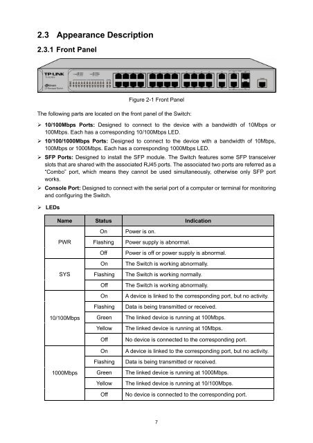
- Page 13: Chapter 2 IntroductionThanks for ch
- Page 17 and 18: Figure 3-3 Main Setup-MenuNote:Clic
- Page 19 and 20: Indicates the 100Mbps port is at th
- Page 21 and 22: Device Location:System Contact:Ente
- Page 23 and 24: IP Address Mode:Management VLAN:IP
- Page 25 and 26: Password:Confirm Password:Type a pa
- Page 27 and 28: Figure 4-11 Firmware UpgradeNote:1.
- Page 29 and 30: Figure 4-14 Access ControlThe follo
- Page 31 and 32: Figure 4-15 SSL ConfigThe following
- Page 33 and 34: ‣ Key DownloadKey Type:Key File:D
- Page 35 and 36: 3. On the Web management page of th
- Page 37 and 38: Chapter 5 SwitchingSwitching module
- Page 39 and 40: Figure 5-2 Mirroring PortThe follow
- Page 41 and 42: enabled, the outgoing packets sent
- Page 43 and 44: Note:1. The Port Security function
- Page 45 and 46: Figure 5-6 LAG TableThe following e
- Page 47 and 48: Description:Give a description to t
- Page 49 and 50: preferred one. If the two port prio
- Page 51 and 52: automatically.Refresh Rate:Enter a
- Page 53 and 54: Figure 5-12 Address TableThe follow
- Page 55 and 56: Search Option:Select a Search Optio
- Page 57 and 58: Select:MAC Address:VLAN ID:Port:Typ
- Page 59 and 60: Chapter 6 VLANThe traditional Ether
- Page 61 and 62: (2) TRUNK: The TRUNK port can be ad
- Page 63 and 64: Figure 6-4 Create or Modify 802.1Q
- Page 65 and 66:
Link Type:PVID:LAG:VLAN:Select the
- Page 67 and 68:
6.2.1 Protocol VLANOn this page, yo
- Page 69 and 70:
Figure 6-9 Enable Protocol VLAN for
- Page 71 and 72:
6.4 Application Example for Protoco
- Page 73 and 74:
Hold Timer: When a GARP entity rece
- Page 75 and 76:
Fixed: In this mode, a port cannot
- Page 77 and 78:
• Port: Port 3 is the root port o
- Page 79 and 80:
Tips:In a STP with stable topology,
- Page 81 and 82:
Figure 7-3 Port rolesThe Spanning T
- Page 83 and 84:
that occur in a specific region bef
- Page 85 and 86:
Figure 7-6 Port ConfigThe following
- Page 87 and 88:
Figure 7-7 Region ConfigThe followi
- Page 89 and 90:
Figure 7-9 Instance Port ConfigThe
- Page 91 and 92:
A CIST and its secondary root bridg
- Page 93 and 94:
7.4.2 TC ProtectWhen TC Protect is
- Page 95 and 96:
• Configure Switch B:Step Operati
- Page 97 and 98:
‣ Suggestion for Configuration•
- Page 99 and 100:
1. Multicast IP Address:As specifie
- Page 101 and 102:
The host, running IGMPv1, does not
- Page 103 and 104:
Figure 8-5 Port ConfigThe following
- Page 105 and 106:
Select:VLAN ID:Router Port Time:Mem
- Page 107 and 108:
5. After a multicast VLAN is create
- Page 109 and 110:
8.2.1 Multicast IP TableOn this pag
- Page 111 and 112:
8.3 Multicast FilterWhen IGMP Snoop
- Page 113 and 114:
Max Groups:LAG:Specify the maximum
- Page 115 and 116:
Chapter 9 QoSQoS (Quality of Servic
- Page 117 and 118:
Figure 9-4 SP-Mode2. WRR-Mode: Weig
- Page 119 and 120:
Note:To complete QoS function confi
- Page 121 and 122:
Priority Level:Indicates the priori
- Page 123 and 124:
3 Map the DSCP priority to theprior
- Page 125 and 126:
Figure 9-11 Storm ControlThe follow
- Page 127 and 128:
Port Voice VLANModeAutomatic ModeMa
- Page 129 and 130:
The following entries are displayed
- Page 131 and 132:
Chapter 10 ACLACL (Access Control L
- Page 133 and 134:
End Time:Delete:Displays the end ti
- Page 135 and 136:
The following entries are displayed
- Page 137 and 138:
10.2.5 Extend-IP ACLExtend-IP ACLs
- Page 139 and 140:
Operation:Click the Edit button to
- Page 141 and 142:
Index:Policy Name:Interface:Directi
- Page 143 and 144:
3. The staff of the marketing depar
- Page 145 and 146:
Chapter 11 Network SecurityNetwork
- Page 147 and 148:
Figure 11-2 Manual BindingThe follo
- Page 149 and 150:
Figure 11-4 ARP ScanningThe followi
- Page 151 and 152:
Figure 11-6 Interaction between a D
- Page 153 and 154:
Choose the menu Network Security→
- Page 155 and 156:
11.2 ARP InspectionAccording to the
- Page 157 and 158:
Figure 11-11 ARP Attack - Cheating
- Page 159 and 160:
The IP-MAC Binding function allows
- Page 161 and 162:
The following entries are displayed
- Page 163 and 164:
DoS Attack TypeDescriptionScan SYNF
- Page 165 and 166:
supplicant system. Note that the cl
- Page 167 and 168:
In this mode, packet transmission i
- Page 169 and 170:
exchange information between the sw
- Page 171 and 172:
Authorized:LAG:Displays the authent
- Page 173 and 174:
Chapter 12 SNMP‣ SNMP OverviewSNM
- Page 175 and 176:
The User is configured in a SNMP Gr
- Page 177 and 178:
12.1.3 SNMP GroupOn this page, you
- Page 179 and 180:
Figure 12-6 SNMP UserThe following
- Page 181 and 182:
ead-only: Management right of the C
- Page 183 and 184:
Figure 12-8 Notification ConfigThe
- Page 185 and 186:
The RMON Groups can be configured o
- Page 187 and 188:
Figure 12-11 Alarm ConfigThe follow
- Page 189 and 190:
Chapter 13 ClusterWith the developm
- Page 191 and 192:
The following entries are displayed
- Page 193 and 194:
Detail:Click the Detail button to v
- Page 195 and 196:
‣ Device TableDevice Type:Device
- Page 197 and 198:
Port:NTDP:Displays the port number
- Page 199 and 200:
Cluster:Cluster Role:Displays the c
- Page 201 and 202:
Individual:Select this option to ch
- Page 203 and 204:
4 Configure the member switch On Cl
- Page 205 and 206:
Figure 14-1 CPU MonitorClick the Mo
- Page 207 and 208:
The Log function is implemented on
- Page 209 and 210:
Figure 14-5 Log HostThe following e
- Page 211 and 212:
Pair:Status:Length:Error:Displays t
- Page 213 and 214:
14.4.2 TracertTracert test function
- Page 215 and 216:
Figure 15-2 Open Hyper Terminal2) T
- Page 217 and 218:
Figure 15-6 bootUtil MenuAs the pro
- Page 219 and 220:
Appendix A: SpecificationsIEEE802.3
- Page 221 and 222:
Figure B-25) The following TCP/IP P
- Page 223 and 224:
Appendix C: 802.1X Client SoftwareI
- Page 225 and 226:
Figure C-5 Install the Program6. Th
- Page 227 and 228:
Figure C-8 Preparing Setup3. On the
- Page 229 and 230:
Auto reconnect after timeout: Selec
- Page 231 and 232:
Appendix D: GlossaryAccess Control
- Page 233 and 234:
Layer 2Data Link layer in the ISO 7