ABB i-bus® EIB 4-fold switch sensor solo®, FM Type: 6127-xx
ABB i-bus® EIB 4-fold switch sensor solo®, FM Type: 6127-xx
ABB i-bus® EIB 4-fold switch sensor solo®, FM Type: 6127-xx

You also want an ePaper? Increase the reach of your titles
YUMPU automatically turns print PDFs into web optimized ePapers that Google loves.
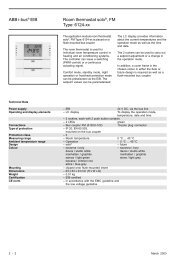
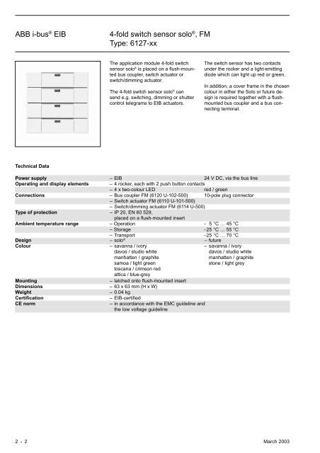
<strong>ABB</strong> i-bus ® <strong>EIB</strong>4-<strong>fold</strong> <strong>switch</strong> <strong>sensor</strong> solo ® , <strong>FM</strong><strong>Type</strong>: <strong>6127</strong>-<strong>xx</strong>The application module 4-<strong>fold</strong> <strong>switch</strong><strong>sensor</strong> solo ® is placed on a flush-mountedbus coupler, <strong>switch</strong> actuator or<strong>switch</strong>/dimming actuator.The 4-<strong>fold</strong> <strong>switch</strong> <strong>sensor</strong> solo ® cansend e.g. <strong>switch</strong>ing, dimming or shuttercontrol telegrams to <strong>EIB</strong> actuators.The <strong>switch</strong> <strong>sensor</strong> has two contactsunder the rocker and a light-emittingdiode which can light up red or green.In addition, a cover frame in the chosencolour in either the Solo or future designis required together with a flushmountedbus coupler and a bus connectingterminal.Technical DataPower supply – <strong>EIB</strong> 24 V DC, via the bus lineOperating and display elements – 4 rocker, each with 2 push button contacts– 4 x two-colour LED red / greenConnections – Bus coupler <strong>FM</strong> (6120 U-102-500) 10-pole plug connector– Switch actuator <strong>FM</strong> (6110 U-101-500)– Switch/dimming actuator <strong>FM</strong> (6114 U-500)<strong>Type</strong> of protection – IP 20, EN 60 529,placed on a flush-mounted insertAmbient temperature range – Operation - 5 °C … 45 °C– Storage -25 °C … 55 °C– Transport -25 °C … 70 °CDesign – solo ® – futureColour – savanna / ivory – savanna / ivorydavos / studio whitedavos / studio whitemanhatten / graphitemanhatten / graphitesamoa / light greenstone / light greytoscana / crimson redattica / blue-greyMounting– latched onto flush-mounted insertDimensions – 63 x 63 mm (H x W)Weight– 0.04 kgCertificationCE norm– <strong>EIB</strong>-certified– in accordance with the EMC guideline andthe low voltage guideline2 - 2 March 2003
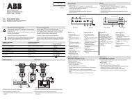
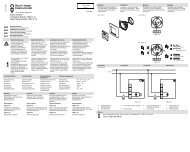
<strong>ABB</strong> i-bus ® <strong>EIB</strong>4-<strong>fold</strong> <strong>switch</strong> <strong>sensor</strong> solo ® , <strong>FM</strong><strong>Type</strong>: <strong>6127</strong>-<strong>xx</strong>Application programs Number of Max. number of Max. number ofcommunication objects group addresses associationsFor Bus coupler <strong>FM</strong>,Switch actuator/<strong>sensor</strong> <strong>FM</strong> andSwitch/dimming actuator <strong>FM</strong>:Switch <strong>sensor</strong> 4f TP/1 15 15 15Operation with the various flush-mounted devices is defined on the “General” parameter page. If the <strong>switch</strong> <strong>sensor</strong> has beenplaced onto a flush-mounted <strong>switch</strong> actuator or <strong>switch</strong>/dimming actuator, it is not necessary to insert a further device from thedatabase in ETS2.Circuit diagram1 42 531 Bus cable 4 Application module2 Bus terminal 5 10-pole plug3 Bus coupler <strong>FM</strong>March 2003 2 - 3
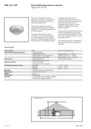
<strong>ABB</strong> i-bus ® <strong>EIB</strong>4-<strong>fold</strong> <strong>switch</strong> <strong>sensor</strong> solo ® , <strong>FM</strong><strong>Type</strong>: <strong>6127</strong>-<strong>xx</strong>Switch <strong>sensor</strong> 4f TP/1Selection in ETS2– <strong>ABB</strong>Push button soloPush button, 4-<strong>fold</strong>The 4-<strong>fold</strong> <strong>switch</strong> <strong>sensor</strong> Solo can beplaced on a flush-mounted bus coupler,<strong>switch</strong> actuator or a <strong>switch</strong>/dimmingactuator. The respective flush-mounteddevice on which the 4-<strong>fold</strong> <strong>switch</strong> <strong>sensor</strong>Solo has been placed, must be setfirst of all on the parameter page “BCUtype”. Only then are the parameters forthe various flush-mounted actuatorsenabled in the ETS2 program.The following section describes thefunctions of the rocker. These functionsare always identical, regardless of theflush-mounted device that is used.Switch <strong>sensor</strong>If the operation mode of the rocker isdefined as “Switch <strong>sensor</strong>”, the <strong>switch</strong><strong>sensor</strong> sends “ON” or “OFF” telegramsvia the relevant 1 bit object “Rocker -Switch”.In the default setting, the <strong>switch</strong> <strong>sensor</strong>sends “TOGGLE” telegrams when theright or left rocker is pressed. This meansthat an “ON” command is sent firstfollowed by an “OFF” command after apush button action and then an “ON”command if the rocker is pressedagain.Via the parameter “Working mode ofrocker”, the rockers can also be set sothat the right rocker sends “ON” commandsand the left rocker sends “OFF”commands or vice versa.Dimming <strong>sensor</strong>In the operation mode “Dimming <strong>sensor</strong>”,an “ON” or “OFF” command issent to the 1 bit communication object“Rocker - Switch” when one of the rokkersis pressed briefly. If the rocker ispressed for a longer period, the <strong>switch</strong><strong>sensor</strong> sends commands for dimmingbrighter or darker to the 4 bit object“Rocker - Dimming”. If the rocker is releasedafter a long push button action,the <strong>switch</strong> <strong>sensor</strong> sends the command“Stop dimming”.In the default setting, the <strong>switch</strong> <strong>sensor</strong>sends “TOGGLE” telegrams after ashort operation of the right or left rokker.A long operation of the left rockerdims down the brightness level while along operation of the right rocker dimsup the brightness level.This behaviour is adapted if requiredvia the parameter “Working mode ofrocker”.Shutter <strong>sensor</strong>In the operation mode “Shutter <strong>sensor</strong>”,the <strong>switch</strong> <strong>sensor</strong> has the 1 bit communicationobjects “Move shutter” and“Adjust shutter”. After a long operationof the rocker, the <strong>switch</strong> <strong>sensor</strong> sendstelegrams to the connected shutter actuatorsto raise or lower the shutter. Aftera short operation, it sends telegramsto stop the shutter movement orfor louvre adjustment.The setting “Working mode of rocker”defines whether the shutter is raised orlowered after operation of the right orleft rocker.Flexible assignmentWith the application “Flexible assignment”,the right and the left side of therocker of the <strong>switch</strong> <strong>sensor</strong> each havetheir own 1 bit communication object“Rocker - Switch” available. It is possibleto send “ON”, “OFF” or “TOGGLE”telegrams on the <strong>EIB</strong> via this object.Each pulse edge of the rockers cantherefore be set individually. The <strong>switch</strong><strong>sensor</strong> can thus be adapted to a widevariety of applications. If e.g. inchingmode should be implemented, the setting“rising = ON, falling = OFF” shouldbe selected.With the parameter setting “no reaction”,it is possible to completely deactivatea rocker.LEDThe relevant LED of the rocker can displaythe current status of the object“Rocker ...” or serve as an orientationlight.If the LED is used for status display, thecolour changes when the object valuechanges. It can freely selected whetherthe LED lights up “green” or “red” in theOFF state or “red” or “green” in the ONstate.The LED can light up “green” or “red”as an orientation light.2 - 4 March 2003
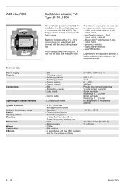
<strong>ABB</strong> i-bus ® <strong>EIB</strong>4-<strong>fold</strong> <strong>switch</strong> <strong>sensor</strong> solo ® , <strong>FM</strong><strong>Type</strong>: <strong>6127</strong>-<strong>xx</strong>Actuator functionsThe following section describes the actuatorfunctions of the flush-mounted<strong>switch</strong> actuator and the <strong>switch</strong>/dimmingactuator.Switch actuator <strong>FM</strong> (6110 U-101-500)The <strong>switch</strong> actuator has a 1 bit communicationobject “Output - Switch” whichis used to <strong>switch</strong> the relay. In the defaultsetting, the output <strong>switch</strong>es on followingthe receipt of a telegram withthe value “1” and <strong>switch</strong>es off after atelegram with the value “0”. If the parameter“Behaviour of contact” is set to“normally closed contact”, the relay isclosed following the receipt of a telegramwith the value “0” and openedafter a telegram with the value “1”.The relay contact is opened on busvoltage failure. The behaviour of therelay contact on mains voltage recoverycan be set. By default, the relay is“opened”. Further options are “closed”or “restore previous state”. If the outputshould carry out defined <strong>switch</strong>ing on/off, the actuator takes into account theparameter “Switching behaviour”.Logic (Switch actuator <strong>FM</strong>,6110 U-101-500)With the parameter “Logic operation”, itis possible to set an AND or an ORfunction. In both cases, the ETS2 programdisplays a further 1 bit communicationobject “Output - ... function” forthe output. The output links the valuesof communication objects no. 0 and no.1 and <strong>switch</strong>es the relay according tothe result.A corresponding parameter is availablefor preselecting a defined input signalon bus voltage recovery.Status (Switch actuator <strong>FM</strong>,6110 U-101-500)If the parameter “Status response” isset to “yes”, the ETS2 program displaysa further 1 bit communication object“Output - Status response”. This communicationobject sends a telegrameach time the actuator is <strong>switch</strong>ed. Thevalue “1” means that the relay has adoptedthe active state in accordancewith the parameter “Behaviour of contact”.Staircase lighting function(Switch actuator <strong>FM</strong>, 6110 U-101-500)In the operation mode “Staircase lightingfunction”, the output is <strong>switch</strong>edon immediately following the receipt ofan “ON” telegram. Once the period thatwas set in the time base and factor parametershas elapsed, the relay is automaticallyopened. If the output receivesfurther “ON” telegrams before the periodhas elapsed, the time restarts.If the staircase lighting function and thelogic operation are activated, the timesetting only has an effect if the actuatoris <strong>switch</strong>ed via object no. 0 “Output -Switch”.In addition to the staircase lightingfunction, it is also possible to activatean ON delay. The corresponding parametermust be activated. The ON delayis again defined with a time base andfactor.Timing function(Switch actuator <strong>FM</strong>, 6110 U-101-500)With the operation mode “Timingfunction”, it is possible to activate anON and/or OFF delay. The two periodscan be of varying lengths and are definedwith a time base and factor.The delay periods only influence the<strong>switch</strong> object. If e.g. an OR functionhas been selected in addition to an ONdelay, the time delay is only active if anON command is received via the <strong>switch</strong>object. If the ON command is howeversent directly to the logic object, the actuator<strong>switch</strong>es directly to the state thatwas preselected in the parameter “Behaviourof contact”.March 2003 2 - 5
<strong>ABB</strong> i-bus ® <strong>EIB</strong>4-<strong>fold</strong> <strong>switch</strong> <strong>sensor</strong> solo ® , <strong>FM</strong><strong>Type</strong>: <strong>6127</strong>-<strong>xx</strong>Communication objectswhen used as a <strong>switch</strong> <strong>sensor</strong>No. <strong>Type</strong> Object name Function6 1 bit Rocker 1 Switch8 1 bit Rocker 2 Switch10 1 bit Rocker 3 Switch12 1 bit Rocker 4 SwitchCommunication objectswhen used as a dimming <strong>sensor</strong>No. <strong>Type</strong> Object name Function6 1 bit Rocker 1, short Switch7 4 bit Rocker 1, long Dimming8 1 bit Rocker 2, short Switch9 4 bit Rocker 2, long Dimming10 1 bit Rocker 3, short Switch11 4 bit Rocker 3, long Dimming12 1 bit Rocker 4, short Switch13 4 bit Rocker 4, long DimmingCommunication objectswhen used as a shutter <strong>sensor</strong>No. <strong>Type</strong> Object name Function6 1 bit Rocker 1, long Move shutter7 1 bit Rocker 1, short Adjust shutter8 1 bit Rocker 2, long Move shutter9 1 bit Rocker 2, short Adjust shutter10 1 bit Rocker 3, long Move shutter11 1 bit Rocker 3, short Adjust shutter12 1 bit Rocker 4, long Move shutter13 1 bit Rocker 4, short Adjust shutterCommunication objectswith flexible assignment of the rockersNo. <strong>Type</strong> Object name Function6 1 bit Rocker 1, right Switch7 1 bit Rocker 1, left Switch8 1 bit Rocker 2, right Switch9 1 bit Rocker 2, left Switch10 1 bit Rocker 3, right Switch11 1 bit Rocker 3, left Switch12 1 bit Rocker 4, right Switch13 1 bit Rocker 4, left Switch2 - 8 March 2003
<strong>ABB</strong> i-bus ® <strong>EIB</strong>4-<strong>fold</strong> <strong>switch</strong> <strong>sensor</strong> solo ® , <strong>FM</strong><strong>Type</strong>: <strong>6127</strong>-<strong>xx</strong>Communication objectswhen used as a <strong>switch</strong> <strong>sensor</strong> withflush-mounted <strong>switch</strong> actuator, ANDfunction and status responseNo. <strong>Type</strong> Object name Function0 1 bit Output Switch1 1 bit Output AND function2 1 bit Output Status response6 1 bit Rocker 1 Switch8 1 bit Rocker 2 Switch10 1 bit Rocker 3 Switch12 1 bit Rocker 4 SwitchCommunication objectswhen used as a <strong>switch</strong> <strong>sensor</strong> withflush-mounted <strong>switch</strong> actuator, ORfunction and status responseNo. <strong>Type</strong> Object name Function0 1 bit Output Switch1 1 bit Output OR function2 1 bit Output Status response6 1 bit Rocker 1 Switch8 1 bit Rocker 2 Switch10 1 bit Rocker 3 Switch12 1 bit Rocker 4 SwitchCommunication objectswhen used as a <strong>switch</strong> <strong>sensor</strong> withflush-mounted dimming actuator, ANDfunction, status response and presetobjectNo. <strong>Type</strong> Object name Function0 1 bit Output Switch1 4 bit Dimmer Rel. dimming2 1 byte Dimmer Brightness value3 1 bit Output AND function4 1 bit Dimmer Status response5 1 bit Dimmer Preset6 1 bit Rocker 1 Switch8 1 bit Rocker 2 Switch10 1 bit Rocker 3 Switch12 1 bit Rocker 4 SwitchCommunication objectswhen used as a <strong>switch</strong> <strong>sensor</strong> withflush-mounted dimming actuator, ORfunction, status response and presetobjectNo. <strong>Type</strong> Object name Function0 1 bit Output Switch1 4 bit Dimmer Rel. dimming2 1 byte Dimmer Brightness value3 1 bit Output OR function4 1 bit Dimmer Status response5 1 bit Dimmer Preset6 1 bit Rocker 1 Switch8 1 bit Rocker 2 Switch10 1 bit Rocker 3 Switch12 1 bit Rocker 4 SwitchMarch 2003 2 - 9
April 2012 Page 917. Promotion of breastfeeding and other interventions to fight malnutrition;18. Surgical repair of fistula;19. Surgeries/procedures to correct cleft palates.TRF considers activities targeting the following to be outside the scope of the maternal and childhealth area of focus and as such are not eligible for global grant funding:1. Life-saving surgeries that do not provide significant capacity building in the projectcountry;2. Medical missions/surgical team trips that do not provide significant capacity building inthe project country.III.Elements of Successful Humanitarian Projects and Vocational Training TeamsGlobal grants are:1. Sustainable – communities are able to address their maternal and child health needs afterthe Rotary club/district has completed its work;2. Measurable – sponsors can select standard measures for their area of focus from theMonitoring and Evaluation Toolkit or use their own measures to show the good results oftheir work;3. Community driven – designed by the host community based upon the needs they haveidentified;4. Aligned with an area of focus – as defined in the policy documents.IV.Elements of Successful ScholarshipsGlobal grants support graduate-level scholarships for career-minded professionals. TRFconsiders the following when evaluating global grant scholarship applications:1. The applicant’s previous work experience in the field of maternal and child health;2. Academic program alignment with maternal and child health. Examples of academicprograms include epidemiology, nutrition, global health, public health, and healthpromotion and degrees in nursing and medicine;3. The applicant’s career plans as they relate to maternal and child health.
<strong>ABB</strong> i-bus ® <strong>EIB</strong>4-<strong>fold</strong> <strong>switch</strong> <strong>sensor</strong> solo ® , <strong>FM</strong><strong>Type</strong>: <strong>6127</strong>-<strong>xx</strong>ParametersThe default setting for the valuesis printed in bold type.Only for flexible assignment:– Reaction on right rocker TOGGLEdefined <strong>switch</strong>ingOnly for defined <strong>switch</strong>ing:– Switch function of right rocker no reactionrising = OFFfalling = OFFrising = OFF, falling = OFFrising = ONfalling = OFFrising = ON, falling = OFFrising = OFF, falling = ONrising = ON, falling = ON– Reaction on left rocker TOGGLEdefined <strong>switch</strong>ingOnly for defined <strong>switch</strong>ing:– Switch function of left rocker no reactionrising = OFFfalling = OFFrising = OFF, falling = OFFrising = ONfalling = OFFrising = ON, falling = OFFrising = OFF, falling = ONrising = ON, falling = ON– Operation mode of LED indicates value of object “Rockerleft”orientation lightOnly if value is displayed:– Colour of the LED UP = green, DOWN = redUP = red, DOWN = greenOnly if orientation light is selected:– Colour of the LED always greenalways redMarch 2003 2 - 11
<strong>ABB</strong> i-bus ® <strong>EIB</strong>4-<strong>fold</strong> <strong>switch</strong> <strong>sensor</strong> solo ® , <strong>FM</strong><strong>Type</strong>: <strong>6127</strong>-<strong>xx</strong>ParametersThe default setting for the valuesis printed in bold type.Additional parameters when used with <strong>switch</strong> actuator <strong>FM</strong> (6110 U-101):Switch actuator - General:– Behaviour of contact normally open contactnormally closed contact– Contact on mains voltage recovery openedclosedrestore previous stateSwitch actuator - Operation modes:– Operation mode Normal operationStaircase lighting functionTiming functionOnly for staircase lighting function:– ON delay noyesOnly if “yes” is selected:– Time base for ON delay approx. 130 ms / … / approx. 520 ms/ … / approx. 1.2 h– Factor for ON delay 10(2…127)– Time base for staircase lighting approx. 130 ms / … / approx. 520 msfunction / … / approx. 1.2 h– Factor for staircase lighting 10function (2…127)Only for timing function:– ON delay noyesOnly if “yes” is selected:– Time base for ON delay approx. 130 ms / … / approx. 520 ms/ … / approx. 1.2 h– Factor for ON delay 10(2…127)– OFF delay noyesOnly if “yes” is selected:– Time base for OFF delay approx. 130 ms / … / approx. 520 ms/ … / approx. 1.2 h– Factor for OFF delay 10(2…127)– Logic operation no logic operationAND functionOR functionOnly if a logic operation is selected:– Value of logic operation on OFF “0”mains voltage recovery ON “1”– Status response noyes2 - 12 March 2003
<strong>ABB</strong> i-bus ® <strong>EIB</strong>4-<strong>fold</strong> <strong>switch</strong> <strong>sensor</strong> solo ® , <strong>FM</strong><strong>Type</strong>: <strong>6127</strong>-<strong>xx</strong>ParametersThe default setting for the valuesis printed in bold type.Additional parameters when used with dimming actuator <strong>FM</strong> (6114 U):Dimming actuator - General:– Behaviour on change in the jump to valuebrightness valuedim to value– Brightness value for ON telegram final valueparameterised valueOnly for parameterised value:– Initial brightness value OFF / 10 % / … / 90 % / 100 %– Brightness value on mains voltage 10 % brightnessrecovery– Mode for parallel operation of several masterflush-mounted dimming actuators slave100 % brightnessfinal valueOFFDimming actuator - Operation modes:– Operation mode Normal operationStaircase lighting functionTiming functionOnly for staircase lighting function:– ON delay noyesOnly for ON delay:– Time base for ON delay approx. 130 ms / … / approx. 520 ms/ … / approx. 1.2 h– Factor for ON delay 10(2…127)– Time base for staircase lighting approx. 130 ms / … / approx. 4.2 sfunction/ … / approx. 1.2 h– Factor for staircase lighting function 43(2…127)– Enable time extension noyesOnly if “yes” is selected:– ON delay noyesOnly if “yes” is selected:– Time base for ON delay approx. 130 ms / … / approx. 520 ms/ … / approx. 1.2 h– Factor for ON delay 10(2…127)– OFF delay noyesOnly if “yes” is selected:– Time base for OFF delay approx. 130 ms / … / approx. 520 ms/ … / approx. 1.2 h– Factor for OFF delay 10(2…127)– Logic operation no logic operationAND functionOR function– Status response noyesMarch 2003 2 - 13
<strong>ABB</strong> i-bus ® <strong>EIB</strong>4-<strong>fold</strong> <strong>switch</strong> <strong>sensor</strong> solo ® , <strong>FM</strong><strong>Type</strong>: <strong>6127</strong>-<strong>xx</strong>ParametersThe default setting for the valuesis printed in bold type.Dimming rate:– Time base for passing through the approx. 0.5 msdimming rangeapprox. 8.0 msapprox. 130 msapprox. 2.1 sapprox. 33 s– Factor for passing through the 20dimming range– Note:Time base * Factor * 255Read-only memory:– Number of objects none1Only if “1” is selected:– Behaviour on receipt of an ON set preselected brightness valuetelegram– Brightness value for read-only OFF / 10 % / … / 30 % / … / 100 %memory (object no. 5 = ON)– Behaviour on receipt of an OFF no reactiontelegramset preselected brightness valueOnly for preselected brightness value:– Brightness value for read-only OFF / 10 % / 20 % / … / 100 %memory (object no. 5 = OFF)2 - 14 March 2003