ABB i-bus® EIB Room thermostat solo®, FM Type: 6124-xx
ABB i-bus® EIB Room thermostat solo®, FM Type: 6124-xx
ABB i-bus® EIB Room thermostat solo®, FM Type: 6124-xx

Create successful ePaper yourself
Turn your PDF publications into a flip-book with our unique Google optimized e-Paper software.
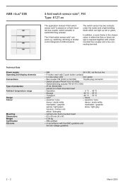
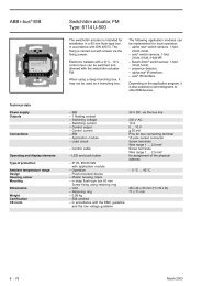
<strong>ABB</strong> i-bus ® <strong>EIB</strong><strong>Room</strong> <strong>thermostat</strong> solo ® , <strong>FM</strong><strong>Type</strong>: <strong>6124</strong>-<strong>xx</strong>The application module room <strong>thermostat</strong>solo ® , <strong>FM</strong> <strong>Type</strong>: <strong>6124</strong>-<strong>xx</strong> is placed on aflush-mounted bus coupler.The room <strong>thermostat</strong> is used forindividual room temperature control inheating and air conditioning systems.The controller can issue a switching(PWM control) or a continuousactuating signal.Comfort mode, standby mode, nightoperation or frost/heat protection modecan be preselected via the <strong>EIB</strong>. Thesetpoint values can be parameterised.The LC display provides informationabout the current temperatures and theoperation mode as well as the timeand date.The 2 rockers can be used to carry outa setpoint adjustment or a change inthe operation mode.In addition, a cover frame in thechosen colour in either the Solo orfuture design is required as well as aflush-mounted bus coupler.Technical DataPower supply – <strong>EIB</strong> 24 V DC, via the bus lineOperating and display elements – LC display To display the operation mode,temperature, date and time– 2 rockers, each with 2 push button contacts– 2 LEDs greenConnections – Bus coupler <strong>FM</strong> (6120U-102) 10-pole plug connector<strong>Type</strong> of protection – IP 20, EN 60 529,mounted on the bus couplerProtection class–IIMeasuring range – <strong>Room</strong> temperature 0 °C … 40 °CAmbient temperature range – Operation - 5 °C … 45 °CDesign – solo ® – futureColour – savanna / ivory – savanna / ivorydavos / studio whitedavos / studio whitemanhatten / graphitemanhatten / graphitesamoa / light greenstone / light greytoscana / crimson redattica / blue-greyMounting– clipped onto flush-mounted insertDimensions – 63 x 63 x 23 mm (H x W x D)Weight– 0.01 kgCertificationCE norm– <strong>EIB</strong>-certified– in accordance with the EMC guideline andthe low voltage guideline2 - 2 March 2003
<strong>ABB</strong> i-bus ® <strong>EIB</strong><strong>Room</strong> <strong>thermostat</strong> solo ® , <strong>FM</strong><strong>Type</strong>: <strong>6124</strong>-<strong>xx</strong>Continuous / Switch Heat Cool TP/4Selection in ETS2– <strong>ABB</strong>HeatingThermostatThe application program is intendedfor the application module room<strong>thermostat</strong> solo.The room <strong>thermostat</strong> is able to usevarious operating modes and setpointvalues to heat or cool a room. They canbe selected and modified via the busor via the rockers.A green LED is available for each ofthe two rockers. They can bepermanently switched on or off via theparameter “Function of LED”.Various communication objects aredisplayed or hidden depending on theparameter settings.LC displayThe room <strong>thermostat</strong> has an LCdisplay. The current room temperature(actual value) is displayed by default.By modifying the parameter“Temperature display in normaloperating mode”, it is possible todisplay the current setpoint or therelative setpoint which is produced bysetpoint adjustment via rocker 1.Alternatively, the display can bedeactivated completely.In addition, the current operating modeand/or the time and date can be readin the LC display using varioussymbols. The display of the time anddate is dependent on the parametersfor the info lines. The time and date arenot displayed by default.If e.g. the current time or date shouldbe read in the info line, the parameter“Content of info line” should be setaccordingly. In addition, the groupaddress “Time” and/or “Date” must belinked with the corresponding object ofthe room <strong>thermostat</strong>.The time and date can e.g. be sent bya visualisation terminal or a clock witha DCF77 receiver.The setting “Display of heat/cool isactive” describes when the symbols“Heat” or “Cool” are displayed. Thesetting “when heating or cooling isrequired” means that the symbols arealso displayed if the frost or heatprotection mode is active. In the setting“if operation mode is active”, thesymbols are displayed if heating orcooling is actually being carried out.The LCD can be lit if required. Theparameter “LCD lighting” is availablefor this purpose. It is thus possible forthe LCD lighting to be always switchedon or off or to use the lightingdepending on the communicationobject “Backlighting for display”.Operation modesThe room <strong>thermostat</strong> has fouroperation modes:– Frost protection mode: The room<strong>thermostat</strong> is out of service; heatingis only carried out if the roomtemperature drops so low that thereis a risk of the heating installationfreezing.– Comfort mode: The setpoint for theroom temperature is set to a valuewhich enables normal use of theroom at a pleasant temperature.– Standby mode: The roomtemperature drops so low (e.g.during periods of absence) that theheating costs are saved. The comforttemperature can however bereached again quickly.– Night operation: The room is notused for long periods during thenight; the room temperature isreduced to a pleasant temperatureduring the night and can be raisedrelatively quickly again in themorning.Night Comfort Frost/heatobject object protection objectFrost prot. 1Comfort 1 0Night 1 0Standby 0Operation mode2 - 4 March 2003
<strong>ABB</strong> i-bus ® <strong>EIB</strong><strong>Room</strong> <strong>thermostat</strong> solo ® , <strong>FM</strong><strong>Type</strong>: <strong>6124</strong>-<strong>xx</strong>It is possible to switch between theseoperation modes using switchingtelegrams (see also the diagram of theoperation modes). The frost/heatprotection mode has the highestpriority i.e. it is not possible to switch toanother operation mode in this case.The frost/heat protection mode mustfirst be deactivated i. e. by closing anopened window. Comfort mode has thenext highest priority followed by nightoperation. If none of these threeoperation modes are active, the room<strong>thermostat</strong> is in standby mode.Party time (comfort extension)If the room <strong>thermostat</strong> is switched tonight operation via the bus, it ispossible to active party time bypressing the right side of rocker 2(changes to comfort mode). Once theparty time has elapsed, the <strong>thermostat</strong>switches back to night operation.During the party time, the symbols fornight operation and comfort mode areshown on the display. By pressing theleft side of rocker 2, the party time canbe manually reset to night operation.This function can also be used for thetemporary deactivation of heat andfrost protection modes. As during nightoperation, the device switches tocomfort mode for the set period. Theswitching on and off of the function iscarried out in the same way. Duringthis comfort extension, the symbols forfrost protection and comfort areindicated on the display.SetpointsThe following setpoints can be set forthe heating mode: “Base setpoint in °C(16..35) (comfort temperature)”,“Reduced heating in standby mode inK (1..8)”, “Reduced heating during thenight in K (1..12)” and “Setpoint frostprotection in °C (5..10)”.The comfort temperature for thecooling mode can be set via the“Insensitive range between heat andcool in K (1-10)”. The setpoints forstandby and night operation refer tothis value: “Increased cooling instandby mode in K (1..8)” and“Increased cooling during the night inK (1..12)”.If cooling should take place at 25°Ce.g. with a base setpoint of 22°C incomfort mode, an insensitive zone of3°C must be set. If cooling should thentake place in standby mode at 27°C,the value must be increased by 2°C.An increase of 4°C is required forcooling during night operation from29°C.To prevent the uncontrolledoverheating of rooms, it is possible topreselect a setpoint for heat protectionmode to specify when cooling shouldtake place. If heat protection is notrequired, the cooling can be switchedoff. In this case, the value 99.9°C isshown on the display on receipt of an“On” telegram at the frost/heatprotection object instead of the currentsetpoint and the value “99.84 °C” issent on the <strong>EIB</strong>.The base setpoint can be modified viathe bus as often as required. To do so,a 2 byte temperature value must besent to the object “Base setpoint”.The setpoint temperature can bemanually changed with the first rocker.The parameters “Range for manualsetpoint selection”, “Maximumincrease of setpoint for heating” and“Maximum reduction of setpoint forcooling” specify the scope forchanging the setpoint. If a newtelegram is sent to the communicationobject “Base setpoint” after a manualsetpoint adjustment, it is thus alsopossible to reverse the manualsetpoint adjustment again.Heat / CoolSo that the room <strong>thermostat</strong> canaddress the various controller types forheating or cooling mode, it can beparameterised as a continuous orswitching controller. In the case of aswitching controller, it is possible tochoose between a PWM controller anda 2-step controller.In the case of a continuous controlresponse and a switching PWMcontroller, the preset controlparameters can be used via thesystem type of the heating or airconditioning system. If other controlparameters are required, they can beset individually via more detailedparameterisation. This should only beused if you have sufficient experiencein the control technology.March 2003 2 - 5
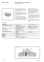
<strong>ABB</strong> i-bus ® <strong>EIB</strong><strong>Room</strong> <strong>thermostat</strong> solo ® , <strong>FM</strong><strong>Type</strong>: <strong>6124</strong>-<strong>xx</strong>Temp.NachtbetriebBetriebFrost/Hitzschutz-Sollwert HitzeschutzKomfortbetriebStandbybetriebSollwerteKühlenSollwerteHeizenRegler kühlt,wenn Istwert > Kühlen SollwertAnhebungNachtAnhebung KühlenStandbyKühlenTotzone zwischen Regler fordert keine LeistungHeizen und Kühlen ( Stellgröße = 0 )AbsenkungStandbyBasis-SollwertHeizenAbsenkungNachtHeizenRegler heizt,wenn Istwert < Heizen SollwertSollwert FrostschutzSollwerte in den verschiedenen Betriebsarten, wenn Heizen und Kühlen aktivThe continuous controller issues itscontrol value to a 1 byte object. Toprotect electrothermal valves whichare connected to heating actuatorswith PWM control, it is advisable tolimit the dynamic range. This is carriedout via the parameter “Minimumcontrol value” or “Maximum controlvalue”. If e.g. a maximum control valueof 80% is preset, the <strong>thermostat</strong> alwaysautomatically sends the value 255when a control value of 204 has beenexceeded.To prevent unnecessary loading of thebus, it is possible to specify the sizethat the change at the control valuemust reach in order to be sent on thebus. The setting is carried out as apercentage value. The sending of thecontrol value is also restricted by acyclic period if it has not beenchanged. This cyclic period should notbe too short (e.g. every 10 min).In the case of a switching PWMcontroller, the output value of thecontroller (0...255) is converted intoON/OFF control. If e.g. a control valueof 70% should be sent, the ON timeshould be set at 7 minutes and theOFF time at 3 minutes with a presetcyclic period of 10 minutes. Thedynamic range can be restricted aswith the continous controller.To optimise the control characteristicsof the heating or cooling system, the“Cyclic time of the switching controlvalue” can be set.The type of heating or cooling as wellas the valve drive used must be takeninto account when setting the cyclictime. The following recommendationscan be implemented:a)Electrothermal valve driveTo open a thermoelectric valve drivefully takes approx. 2-3 minutes. Ashorter cyclic time than 15 minutes istherefore not advisable.b)Floor heatingThe time constant for floor heating isvery large. A cyclic time of 20minutes is therefore sufficient.c) Warm water heatingThermoelectric valve drives are oftenused in this case. A cyclic period of15 minutes produces extremelygood results.d)Electric convector heatingCyclic times between 10 and 15minutes are recommended,depending on the electric heatingand conditions in the room.If a 2-step controller is used for heatingor cooling control, it is possible toselect various levels for the hysteresisby which the setpoint fluctuates. Forexample, if the setpoint during heatingmode is at 20°C and the hysteresis isat 0.5 K, the controller switches on at19.5°C and off again at 20.5°C. Thehysteresis is then based on howquickly the heating system can warmup the room or how quickly the coolingsystem can lower the temperature inthe room as well as the customer‘ssensitivity to temperature levels.2 - 6 March 2003
<strong>ABB</strong> i-bus ® <strong>EIB</strong><strong>Room</strong> <strong>thermostat</strong> solo ® , <strong>FM</strong><strong>Type</strong>: <strong>6124</strong>-<strong>xx</strong>The hysteresis should not be set toolow as otherwise the valve drivecontinually opens and closes. It shouldalso not be set too high as thetemperature fluctuations in the roomare then fairly considerable.The parameter “Reduction ofhysteresis” is used to increase thelevel of accuracy of the controller. If thisparameter is activated, the hysteresisis reduced for example every minuteby 0.1 K until it reaches 0 K, if required.There is effectively a decrease in thetemperature fluctuations during theclosed-loop control as a result of thereduction in the hysteresis. If areduction should be used, it isadvisable to set it at less than a fifth ofthe hysteresis.e.g. Hysteresis 0.5 K =>Reduction < 0.1 K/minIn certain cases (floor heating), it canbe necessary to install a fast-actingadditional level for the heating controlin order to be able to heat the room upquickly. In the setting “2-step heating”,the room <strong>thermostat</strong> can control asecond heating system via a switchingcontroller (1 bit) or via a semicontinuouscontroller with the 1 bytevalues of 0% and 100%.With the parameters “Differencebetween basic heating and additionalheating” and “Hysteresis (one-sided)”,it is determined when the additionallevel is switched on and when it isswitched off.Automatic shadingTo prevent the room from warming updue to sunlight, automatic shading cantake place by lowering one or severalblinds. The shading object “Move” isused for this purpose.The parameter “Automatic shading ...”determines at which temperature theblinds should be lowered.If the temperature again falls below theset shading temperature, no commandis issued to raise the blinds. The blindscan be raised e.g. at a specific timeusing a central command.Group master modeIn large open-plan offices for example,it can be difficult to achieve a goodlevel of control throughout the roomwith only one room <strong>thermostat</strong>. Forthese cases, it is possible to divide theroom into several zones with a room<strong>thermostat</strong> in each zone. So that these<strong>thermostat</strong>s always use the samesetpoint value, it is possible to activatethe parameter “Group master mode”for one of the devices. This device thenhas the 2 byte communication object“Base setpoint for slaves - Telegr.temperature” which is linked to the 2byte communication objects “Basesetpoint - Telegr. temperature” of theother devices. The manual setpointadjustment should be disabled forthese devices.As some valve drives close following a1 byte value of “255” or a 1 bit value of“1” and open at other correspondingvalues, the “Mode of control output“can be inverted.The toggling between heating andcooling is carried out automatically bythe room <strong>thermostat</strong>. If this is notrequired, the “Toggle between heatand cool” can be carried out by anexternal, central controller via the 1 bitobject “Operation mode - Heat/Cool”.In this setting, the heating or coolingsymbols are permanently visibleduring the corresponding operationmode. The object is enabled via theparameter “Toggle between heat andcool”.March 2003 2 - 7
<strong>ABB</strong> i-bus ® <strong>EIB</strong><strong>Room</strong> <strong>thermostat</strong> solo ® , <strong>FM</strong><strong>Type</strong>: <strong>6124</strong>-<strong>xx</strong>OffsetIf the measured temperature becomesinvalid because the bus coupler itselfhas warmed up, it is possible to set an“Offset for temperaturemeasurement...”.The installation site of the <strong>thermostat</strong>and the suitable selection of parametersettings is a decisive factor in accuratetemperature measurements.Communication objectsfor heating and cooling,with switching control valuesNo. <strong>Type</strong> Object name Function1 1 bit Backlighting for display Switch3 1 bit Operation mode Frost/heat protection4 1 bit Operation mode Night operation5 1 bit Operation mode Comfort mode6 1 bit Control value Heat (switching)7 1 bit Control value Cool (switching)8 2 byte Actual temperature Telegr. actual temperature9 2 byte Base setpoint Telegr. temperature10 2 byte Current setpoint Telegr. temperatureCommunication objectsfor display of time and date,automatic shading,2-step heating,continuous control valuesNo. <strong>Type</strong> Object name Function…2 1 bit Autom. shading Telegr. move Up-Down…6 1 byte Control value Heat (continuous)7 1 byte Control value Additional heating (continuous)…12 3 byte Info line Date13 3 byte Info line Time and dayCommunication objectsfor heating and cooling with,external toggling of operation mode,active group master modeNo. <strong>Type</strong> Object name Function…6 1 byte Control value Heat (continuous)7 1 byte Control value Cool (continuous)…10 2 byte Base setpoint for slaves Telegr. temperature11 1 bit Operation mode Heat/cool…2 - 8 March 2003
<strong>ABB</strong> i-bus ® <strong>EIB</strong><strong>Room</strong> <strong>thermostat</strong> solo ® , <strong>FM</strong><strong>Type</strong>: <strong>6124</strong>-<strong>xx</strong>ParametersThe default setting for the valuesis printed in bold type.General:– Function of rocker 1 no functionsetpoint adjustment– Function of LED 1 always OFFgreen orientation light– Function of rocker 2 no functiontoggle between standby/comfort– Function of LED 2 always OFFgreen orientation light– LCD lighting always ONalways OFFacc. to object value (1=ON, 0=OFF)acc. to inverted object value, e.g. fornight operation– Content of info line line is emptydatetimealternate date and timeOnly if display of date and time is selected:– Change interval for info line 2 s / 4 s / 6 s / 8 s– Day format German (MO, DI, MI, DO, FR, SA, SO)English (MON, TUE, WED, THU, …)– Date format German (TT.MM.JJ)English (MM.TT.JJ)Controller general:– Used control functions Heating and coolingHeating2-step heating– Party time (comfort extension) inactive30 min1 hour1.5 hours2 hours2.5 hours3 hours4 hours– Frost/heat protection can be manually enabledselected (comfort extension)disabled– Temperature display in normal actual valueoperating modecurrent setpointno temperature displayrel. current setpoint (+/– K)– Temperature display in adjustment setpoint temperaturemode rel. current temperature (+/– K)– Display of heat/cool is active when heating or cooling is requiredif operation mode is active– Operation mode after reset ComfortStandbyNightFrost/heat protection– Automatic shading inactive(see also “Setpoints”)active– Group master mode inactiveactiveMarch 2003 2 - 9
<strong>ABB</strong> i-bus ® <strong>EIB</strong><strong>Room</strong> <strong>thermostat</strong> solo ® , <strong>FM</strong><strong>Type</strong>: <strong>6124</strong>-<strong>xx</strong>ParametersThe default setting for the valuesis printed in bold type.<strong>Room</strong> temperature:– Change of current setpoint for inactiveautomatic sendingat 0.2 Kat 0.4 Kat 0.6 K…at 2.0 K– Send current setpoint if changes inactiveactive– Cyclic time for autom. sending no cyclical sendingof temp. differenceevery 3 min…every 20 minevery 30 minevery 60 min– Offset for temperature measurement –128 … 0 … 127(change in measured value by(-128 … 127)x0.1 K)– Detection of actual temperature internallyexternallySetpoints:– Base setpoint in °C (16 … 31) 21 °C(comfort temperature for heating)– Reduced heating in standby mode 4 Kin K (1…8)– Reduced heating during the night 4 Kin K (1…8)– Setpoint frost protection in °C (5…10) 7 °COnly for heating and cooling:– Insensitive range between heat 4 Kand cool in K (1 … 8)– Increased cooling in standby mode 2 Kin K (1 … 8)– Increased cooling during the night 4 Kin K (1 … 8)– Setpoint heat protection cooling disabled /30 °C / 35 °C / 40 °C / 44 °C– Toggle between heat and cool automaticallyexternally2 - 10 March 2003
<strong>ABB</strong> i-bus ® <strong>EIB</strong><strong>Room</strong> <strong>thermostat</strong> solo ® , <strong>FM</strong><strong>Type</strong>: <strong>6124</strong>-<strong>xx</strong>ParametersThe default setting for the valuesis printed in bold type.Heating:– Output of control value continuous / switchingFor switching control value:– Control type Two-step control / PWM controlOnly for two-step control:– Hysteresis 0.3 K / 0.5 K / 0.7 K / 1.0 K / 1.5 K / 2 K– Reduction of hysteresis inactive0.2 K/min…0.029 K/min– Cyclic time for automatic inactivesending…every 20 minevery 30 minevery 60 min– Mode of control output normal / invertedOnly for PWM control:– Control parameter by installation typemore detailedOnly if “by installation type” is selected:– <strong>Type</strong> of heating Warm water heating (1.5 K/100 min)Electrical heating (1.5 K/50 min)Floor heating (4 K/200 min)Only if “more detailed” is selected:– Proportional range 1 K / 1.5 K / … / 10 K– Readjust time in min. 0 min / 10 min / … / 100 min / 120 min /… / 240 min– Cyclic time of the switching 3 min / 5 min / 10 min / 15 min /control value20 min / 30 min– PWM cycle is 0% up to an 0 % / 5 % / 10 % / … / 30 %output value– PWM cycle is 100% down to 70 % / … / 90 % / 95 % / 100 %an output value– Mode of control output normal / invertedFor continous control value:– Control parameter by installation typemore detailedOnly if “by installation type” is selected:– <strong>Type</strong> of heating Warm water heating (1.5 K/100 min)Electrical heating (1.5 K/50 min)Floor heating (4 K/200 min)Only if “more detailed” is selected:– Proportional range 1 K / 1.5 K / … / 10 K– Readjust time in min. 0 min / 10 min / … / 100 min / 120 min /… / 240 min– Minimum control value 0 % / 5 % / 10 % / … / 30 %– Maximum control value 70 % / … / 90 % / 95 % / 100 %– Cyclic time for automatic sending inactiveof control output…every 20 minevery 30 minevery 60 min– Mode of control output normal / invertedAdditional heating:– Difference between basic heating 1 K / 2 K / 3 Kand additional heating– Hysteresis (one-sided) 0.15 K / … / 1.0 K– Cyclic time for automatic sending no cyclical sending / every 3 min /of control value… / every 15 min / … / every 60 min– <strong>Type</strong> of control value semi-continuous (1 byte: 0% or 100%)switching (1 bit)– Mode of control output normal / invertedMarch 2003 2 - 11
<strong>ABB</strong> i-bus ® <strong>EIB</strong><strong>Room</strong> <strong>thermostat</strong> solo ® , <strong>FM</strong><strong>Type</strong>: <strong>6124</strong>-<strong>xx</strong>ParametersThe default setting for the valuesis printed in bold type.Cooling:– Output of control value continuous / switchingFor switching control value:– Control type Two-step control / PWM controlOnly for two-step control:– Hysteresis 0.3 K / 0.5 K / 0.7 K / 1.0 K / 1.5 K / 2 K– Reduction of hysteresis inactive0.2 K/min…0.029 K/min– Cyclic time for automatic inactivesending…every 20 minevery 30 minevery 60 min– Mode of control output normal / invertedOnly for PWM control:– Control parameter by installation typemore detailedOnly if “by installation type” is selected:– <strong>Type</strong> of cooling Cooling ceiling (5 K/240 min)SplitUnit / convector fan(4 K/90 min)Only if “more detailed” is selected:– Proportional range 1 K / … / 4 K / … / 10 K– Readjust time in min. 0 min / 10 min / … / 90 min / 120 min /… / 240 min– Cyclic time of the switching 3 min / 5 min / 10 min / 15 min /control value20 min / 30 min– PWM cycle is 0% up to an 0 % / 5 % / 10 % / … / 30 %output value– PWM cycle is 100% down to 70 % / … / 90 % / 95 % / 100 %an output value– Mode of control output normal / invertedFor continuous control value:– Control parameter by installation typemore detailedOnly if “by installation type” is selected:– <strong>Type</strong> of cooling Cooling ceiling (5 K/240 min)SplitUnit / convector fan(4 K/90 min)Only if “more detailed” is selected:– Proportional range 1 K / … / 4 K / … / 10 K– Readjust time in min. 0 min / 10 min / … / 90 min / 120 min /… / 240 min– Minimum control value 0 % / 5 % / 10 % / … / 30 %– Maximum control value 70 % / … / 90 % / 95 % / 100 %– Cyclic time for automatic sending inactiveof control output…every 20 minevery 30 minevery 60 min– Mode of control output normal / inverted2 - 12 March 2003
<strong>ABB</strong> i-bus ® <strong>EIB</strong><strong>Room</strong> <strong>thermostat</strong> solo ® , <strong>FM</strong><strong>Type</strong>: <strong>6124</strong>-<strong>xx</strong>ParametersThe default setting for the valuesis printed in bold type.Manual setpoint selection:– Range for manual setpoint selection disabled+/– 1 K+/– 3 K+/– 5 KOnly for manual selection:– Maximum increase of setpoint 0 K / 1 K / 2 K / 3 K / 4 K / 5 Kfor heating– Maximum reduction of setpoint 0 K / 1 K / 2 K / 3 K / 4 K / 5 Kfor cooling– Exp.: Range for setpoint selection:+/– 5KMax. increase in heating: 3 K Setting range for heating –5K to +3KMax. reduction in cooling: 1 K Setting range for cooling –1K to +5K– Behaviour on receipt of a manual setpoint selection unchangedbase setpointreset manual setpoint selectionMarch 2003 2 - 13