<strong>ABB</strong> i-bus ® <strong>EIB</strong><strong>Room</strong> <strong>thermostat</strong> solo ® , <strong>FM</strong><strong>Type</strong>: <strong>6124</strong>-<strong>xx</strong>It is possible to switch between theseoperation modes using switchingtelegrams (see also the diagram of theoperation modes). The frost/heatprotection mode has the highestpriority i.e. it is not possible to switch toanother operation mode in this case.The frost/heat protection mode mustfirst be deactivated i. e. by closing anopened window. Comfort mode has thenext highest priority followed by nightoperation. If none of these threeoperation modes are active, the room<strong>thermostat</strong> is in standby mode.Party time (comfort extension)If the room <strong>thermostat</strong> is switched tonight operation via the bus, it ispossible to active party time bypressing the right side of rocker 2(changes to comfort mode). Once theparty time has elapsed, the <strong>thermostat</strong>switches back to night operation.During the party time, the symbols fornight operation and comfort mode areshown on the display. By pressing theleft side of rocker 2, the party time canbe manually reset to night operation.This function can also be used for thetemporary deactivation of heat andfrost protection modes. As during nightoperation, the device switches tocomfort mode for the set period. Theswitching on and off of the function iscarried out in the same way. Duringthis comfort extension, the symbols forfrost protection and comfort areindicated on the display.SetpointsThe following setpoints can be set forthe heating mode: “Base setpoint in °C(16..35) (comfort temperature)”,“Reduced heating in standby mode inK (1..8)”, “Reduced heating during thenight in K (1..12)” and “Setpoint frostprotection in °C (5..10)”.The comfort temperature for thecooling mode can be set via the“Insensitive range between heat andcool in K (1-10)”. The setpoints forstandby and night operation refer tothis value: “Increased cooling instandby mode in K (1..8)” and“Increased cooling during the night inK (1..12)”.If cooling should take place at 25°Ce.g. with a base setpoint of 22°C incomfort mode, an insensitive zone of3°C must be set. If cooling should thentake place in standby mode at 27°C,the value must be increased by 2°C.An increase of 4°C is required forcooling during night operation from29°C.To prevent the uncontrolledoverheating of rooms, it is possible topreselect a setpoint for heat protectionmode to specify when cooling shouldtake place. If heat protection is notrequired, the cooling can be switchedoff. In this case, the value 99.9°C isshown on the display on receipt of an“On” telegram at the frost/heatprotection object instead of the currentsetpoint and the value “99.84 °C” issent on the <strong>EIB</strong>.The base setpoint can be modified viathe bus as often as required. To do so,a 2 byte temperature value must besent to the object “Base setpoint”.The setpoint temperature can bemanually changed with the first rocker.The parameters “Range for manualsetpoint selection”, “Maximumincrease of setpoint for heating” and“Maximum reduction of setpoint forcooling” specify the scope forchanging the setpoint. If a newtelegram is sent to the communicationobject “Base setpoint” after a manualsetpoint adjustment, it is thus alsopossible to reverse the manualsetpoint adjustment again.Heat / CoolSo that the room <strong>thermostat</strong> canaddress the various controller types forheating or cooling mode, it can beparameterised as a continuous orswitching controller. In the case of aswitching controller, it is possible tochoose between a PWM controller anda 2-step controller.In the case of a continuous controlresponse and a switching PWMcontroller, the preset controlparameters can be used via thesystem type of the heating or airconditioning system. If other controlparameters are required, they can beset individually via more detailedparameterisation. This should only beused if you have sufficient experiencein the control technology.March 2003 2 - 5
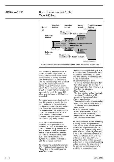
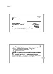
<strong>ABB</strong> i-bus ® <strong>EIB</strong><strong>Room</strong> <strong>thermostat</strong> solo ® , <strong>FM</strong><strong>Type</strong>: <strong>6124</strong>-<strong>xx</strong>Temp.NachtbetriebBetriebFrost/Hitzschutz-Sollwert HitzeschutzKomfortbetriebStandbybetriebSollwerteKühlenSollwerteHeizenRegler kühlt,wenn Istwert > Kühlen SollwertAnhebungNachtAnhebung KühlenStandbyKühlenTotzone zwischen Regler fordert keine LeistungHeizen und Kühlen ( Stellgröße = 0 )AbsenkungStandbyBasis-SollwertHeizenAbsenkungNachtHeizenRegler heizt,wenn Istwert < Heizen SollwertSollwert FrostschutzSollwerte in den verschiedenen Betriebsarten, wenn Heizen und Kühlen aktivThe continuous controller issues itscontrol value to a 1 byte object. Toprotect electrothermal valves whichare connected to heating actuatorswith PWM control, it is advisable tolimit the dynamic range. This is carriedout via the parameter “Minimumcontrol value” or “Maximum controlvalue”. If e.g. a maximum control valueof 80% is preset, the <strong>thermostat</strong> alwaysautomatically sends the value 255when a control value of 204 has beenexceeded.To prevent unnecessary loading of thebus, it is possible to specify the sizethat the change at the control valuemust reach in order to be sent on thebus. The setting is carried out as apercentage value. The sending of thecontrol value is also restricted by acyclic period if it has not beenchanged. This cyclic period should notbe too short (e.g. every 10 min).In the case of a switching PWMcontroller, the output value of thecontroller (0...255) is converted intoON/OFF control. If e.g. a control valueof 70% should be sent, the ON timeshould be set at 7 minutes and theOFF time at 3 minutes with a presetcyclic period of 10 minutes. Thedynamic range can be restricted aswith the continous controller.To optimise the control characteristicsof the heating or cooling system, the“Cyclic time of the switching controlvalue” can be set.The type of heating or cooling as wellas the valve drive used must be takeninto account when setting the cyclictime. The following recommendationscan be implemented:a)Electrothermal valve driveTo open a thermoelectric valve drivefully takes approx. 2-3 minutes. Ashorter cyclic time than 15 minutes istherefore not advisable.b)Floor heatingThe time constant for floor heating isvery large. A cyclic time of 20minutes is therefore sufficient.c) Warm water heatingThermoelectric valve drives are oftenused in this case. A cyclic period of15 minutes produces extremelygood results.d)Electric convector heatingCyclic times between 10 and 15minutes are recommended,depending on the electric heatingand conditions in the room.If a 2-step controller is used for heatingor cooling control, it is possible toselect various levels for the hysteresisby which the setpoint fluctuates. Forexample, if the setpoint during heatingmode is at 20°C and the hysteresis isat 0.5 K, the controller switches on at19.5°C and off again at 20.5°C. Thehysteresis is then based on howquickly the heating system can warmup the room or how quickly the coolingsystem can lower the temperature inthe room as well as the customer‘ssensitivity to temperature levels.2 - 6 March 2003