Busch-Watchdog presence detector Type: 6131-74-101
Busch-Watchdog presence detector Type: 6131-74-101
Busch-Watchdog presence detector Type: 6131-74-101
- No tags were found...

You also want an ePaper? Increase the reach of your titles
YUMPU automatically turns print PDFs into web optimized ePapers that Google loves.
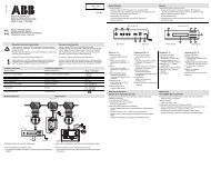
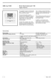
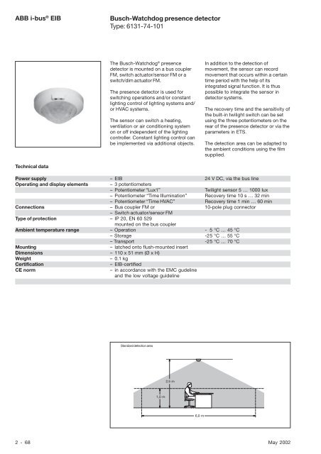
ABB i-bus ® EIB<strong>Busch</strong>-<strong>Watchdog</strong> <strong>presence</strong> <strong>detector</strong><strong>Type</strong>: <strong>6131</strong>-<strong>74</strong>-<strong>101</strong>The <strong>Busch</strong>-<strong>Watchdog</strong> ® <strong>presence</strong><strong>detector</strong> is mounted on a bus couplerFM, switch actuator/sensor FM or aswitch/dim actuator FM.The <strong>presence</strong> <strong>detector</strong> is used forswitching operations and/or constantlighting control of lighting systems and/or HVAC systems.The sensor can switch a heating,ventilation or air conditioning systemon or off independent of the lightingcontroller. Constant lighting control canbe implemented via additional objects.In addition to the detection ofmovement, the sensor can recordmovement that occurs within a certaintime period with the help of itsintegrated signal function. It is thuspossible to integrate the sensor in<strong>detector</strong> systems.The recovery time and the sensitivity ofthe built-in twilight switch can be setusing the three potentiometers on therear of the <strong>presence</strong> <strong>detector</strong> or via theparameters in ETS.The detection area can be adapted tothe ambient conditions using the filmsupplied.Technical dataPower supply – EIB 24 V DC, via the bus lineOperating and display elements –3 potentiometers– Potentiometer “Lux1” Twilight sensor 5 … 1000 lux– Potentiometer “Time Illumination” Recovery time 10 s … 32 min– Potentiometer “Time HVAC” Recovery time 1 min … 60 minConnections – Bus coupler FM or 10-pole plug connector– Switch actuator/sensor FM<strong>Type</strong> of protection – IP 20, EN 60 529mounted on the bus couplerAmbient temperature range – Operation - 5 °C … 45 °C– Storage -25 °C … 55 °C– Transport -25 °C … 70 °CMounting– latched onto flush-mounted insertDimensions – 110 x 51 mm (Ø x H)Weight– 0.1 kgCertificationCE norm– EIB-certified– in accordance with the EMC gudelineand the low voltage guidelineStandard detection area2,5 m1,0 m6,0 m2 - 68 May 2002
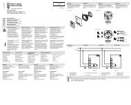
ABB i-bus ® EIB<strong>Busch</strong>-<strong>Watchdog</strong> <strong>presence</strong> <strong>detector</strong><strong>Type</strong>: <strong>6131</strong>-<strong>74</strong>-<strong>101</strong>Application programs Number of Max. number of Max. number ofcommunication objects group addresses associationsFor bus coupler FM:Switch Value Cyclic Monitoring /1 11 29 29Switch Value Cyclic HVAC /1 11 29 29Switch Value Cyclic HVAC Monitoring /1 11 29 29Switch Dim Cyclic HVAC Monitoring Bright. control /1 12 29 28For switch actuator/sensor FM:Switch Value Cyclic Monitoring /2 11 29 29Switch Value Cyclic HVAC /2 11 29 29Switch Value Cyclic HVAC Monitoring /2 11 29 29For switch/dim actuator FM:Schalten Dim Cyclic HVAC Monitoring Bright. control /1 12 29 28Circuit diagrams++EIB-EIB-1 12243LN7872 61 51 Bus cable 5 Switch/dim actuator FM2 Bus terminal 6 Electronic ballast with 0 (1) - 10 Vcontrol input3 Bus coupler FM 7 Supply terminals4 Switch actuator FM 8 230 V mains voltageNoteThe <strong>Busch</strong>-<strong>Watchdog</strong> ® <strong>presence</strong><strong>detector</strong> is solely intended for indooruse e.g. in schools, offices orresidential buildings.The full functionality of the device isdependent on the mounting height.The area of detection can additionallybe adapted via a film that is suppliedwith the device.Application examples and detailedinformation e.g. about “intelligent”HVAC system control and settings forthe potentiometers can be found in theuser manual “<strong>Busch</strong>-<strong>Watchdog</strong><strong>presence</strong> <strong>detector</strong>”.May 2002 2 - 69
ABB i-bus ® EIB<strong>Busch</strong>-<strong>Watchdog</strong> <strong>presence</strong> <strong>detector</strong><strong>Type</strong>: <strong>6131</strong>-<strong>74</strong>-<strong>101</strong>Switch Value Cyclic Monitoring /1Selection in ETS2– ABBPhys. SensorsPresence <strong>detector</strong>Using the application, the <strong>presence</strong><strong>detector</strong> can sense movement in itsfield of detection and send switching orvalue telegrams.The application makes twoindependent channels available whichcan be used to switch on the lighting. Italso has a monitoring function.When assigning parameters, it shouldbe noted that some parameters (ifrequired) are only visible in the “HighAccess” setting and can only then bemodified.SwitchThe <strong>presence</strong> <strong>detector</strong> sendsswitching telegrams to itscommunication objects “Movementchannel ... / Telegr. switch” as soon as itrecords movement in its detectionarea. The value of the switchingtelegram can be set with the parameter“Sending at detection”. It is possible tosend an “ON telegram”, an “OFFtelegram” or “no telegram” ondetection of movement. The “On” or“Off” telegrams can also be sentcyclically.If the <strong>presence</strong> <strong>detector</strong> no longerdetects any movement once therecovery time has elapsed, it ispossible to send an “ON telegram”, an“OFF telegram” or “no telegram”. The“On” or “Off” telegrams can also besent cyclically. The behaviour isspecified with the parameter “Telegramafter recovery time”.Each channel of the <strong>presence</strong> <strong>detector</strong>can be enabled/disabled separately.The communication objects“Movement channel ... / Activation” areused for this purpose. The objects canbe made visible with the parameter.If the <strong>presence</strong> <strong>detector</strong> receives atelegram at this object, the <strong>presence</strong><strong>detector</strong> is activated or deactivated.With the parameters “At .... themovement”, it is possible to selectwhether a telegram is sent once atmovement or once after detection ofmovement or no telegrams are sent viathe communication object “Movementchannel ... / Telegr. switch”.Example:In a functional building, all the<strong>presence</strong> <strong>detector</strong>s should be enabledat a specific time in the morning. A “1”is therefore sent to a central locationwith a time switch and then received atthe communication objects “Movementchannel ... / Activation”. In this example,the parameter “Activation objectmovement” is set to “ON telegram”.ValueValue telegrams can also be sent ondetection of movement. To do so, theparameter “<strong>Type</strong> of movement object”must be changed from “Switching(EIS 1)” to “Value (EIS 6)”. Dimmingactuators can thus be dimmed to avalue that is lower than the maximumvalue e.g. in order to dim on with baselighting.The value that is sent is defined withthe parameters “Sending at thebeginning/end of detection”. It is alsopossible to select that no telegramsare sent.CyclicAll switching telegrams can also besent cyclically. It should be ensuredthat the respective parameter setting“ON telegram cyclically” or “OFFtelegram cyclically” is selected.The total cyclic time can be set usingthe parameters “Time base for cyclicalsending” and “Time factor for cyclicalsending”.The period in which a telegram isrepeated cyclically is composed of abase and a factor:Cyclic time= Base * Factor2 - 70 May 2002
ABB i-bus ® EIB<strong>Busch</strong>-<strong>Watchdog</strong> <strong>presence</strong> <strong>detector</strong><strong>Type</strong>: <strong>6131</strong>-<strong>74</strong>-<strong>101</strong>Channel adjustmentsThe setting of the threshold for the lightsensor as well as the recovery timecan be carried out using thepotentiometer at the back of the<strong>presence</strong> <strong>detector</strong>. There is a separatesetting aid for this purpose. Theillumination threshold is defined forchannel 1 with the “Lux1potentiometer”. The “HVACpotentiometer” presets the illuminationthreshold for channel 2. The“Illumination potentiometer” sets therecovery time for both channels.Alternatively, the settings can becarried out in ETS. To do so, theadjustment parameters should bechanged from “... potentiometer” to“ETS”.With the parameter “Thresholdillumination adjustable with”, thebrightness value that triggers the<strong>presence</strong> <strong>detector</strong> can be indicated.Values between 5 lux and 1000 luxcan be entered. The recovery time canbe set with the two parameters “Timebase of recovery time” and “Time factorof recovery time”. The recovery time isproduced from the base and the factor:Recovery time = Base * FactorBrightness-dependent switchingA further communication object canalso be enabled separately for eachchannel with the parameter “Activationobject brightness dependentswitching”. If the communication object“Brightness dependent switchingchannel ...” receives a “1”, the<strong>presence</strong> <strong>detector</strong> switches on withoutdependence on brightness. Thethreshold settings that have beencarried out with the potentiometer atthe rear of the device or with ETS, donot have any significance for theduration of the activation. If a “0” isreceived at the object, the <strong>presence</strong><strong>detector</strong> only sends “On” telegramsagain once the brightness value hasfallen below the illumination threshold.Light sourceWith an increasing proportion ofexternal light, the <strong>presence</strong> <strong>detector</strong>sends an “Off” telegram as soon as theexternal light has reached the requiredilluminance. The type of light sourcemust be indicated for this purpose.Example:Illuminance 500 luxThe illumination threshold of 500 lux ispreset via the potentiometer on the<strong>presence</strong> <strong>detector</strong> or via the ETSprogram.If movement is now detected in a darkroom in the morning and thebrightness value lies below 500 lux,the <strong>presence</strong> <strong>detector</strong> sends an “On”telegram when it records movement.a) switched light source:When the luminaires are switched on,they generate a luminance of 500 lux.The external light coming in is addedto this. The <strong>presence</strong> <strong>detector</strong> switchesoff if it measures a luminance level of1000 lux.b) controlled light source (constantbrightness):If a conventional constant brightnesscontroller is built into the luminaires,this regulates the proportion of artificiallight so that the measured luminancestays constant at 500 lux. If the<strong>presence</strong> <strong>detector</strong> now records ameasurement of more than 500 lux,the luminaires have already beendimmed down to the minimumbrightness value and are switched off.MonitoringIt is possible to activate a monitoringfunction. To do so, the generalparameter ”Monitoring function” mustbe set to “yes”. The monitoring functionrepresents a “quasi alarm signal”which is not triggered when thesmallest thermal movement is detectedbut when a strong energy source isregistered by the <strong>presence</strong> <strong>detector</strong> ina short space of time or several weaksources are detected during a longerperiod.May 2002 2 - 71
ABB i-bus ® EIB<strong>Busch</strong>-<strong>Watchdog</strong> <strong>presence</strong> <strong>detector</strong><strong>Type</strong>: <strong>6131</strong>-<strong>74</strong>-<strong>101</strong>If the monitoring function is activated, afurther communication object isavailable “Signal / Telegr. ...”. The<strong>presence</strong> <strong>detector</strong> records the intensityand number of movements within atime period and only sends telegramswhen a set sensitivity level has beenexceeded.On a further parameter page“Monitoring function”, it is possible toset the type of the monitoring object(1 bit or 1 byte), the type of telegram atboth the start and end of detection aswell as the cyclical sending behaviour.The parameter “Threshold” indicatesthe sensitivity range. The value “0”denotes maximum sensitivity while thevalue “255” means minimumsensitivity.It can also be parameterised when the<strong>presence</strong> <strong>detector</strong> switches to themonitoring function once it has beenactivated. This period is againcomposed of a time base and factor inthe same way as the cyclic time.If the monitoring function should beenabled externally, this can be carriedout with the communication object“Signal / Activation”. To do so, theparameter “Activation objectmonitoring” must previously be set to“available”.Bus voltage recoveryThe states of the communicationobjects “Movement channel ... / Telegr.switch” adopt a defined status on busvoltage recovery. The states ofchannels 1 and 2 can be definedseparately. There are thus nounnecessary switching operations onbus voltage recovery.Defined states can also be selected forthe objects “Brightness dependentswitching channel ...”. The parametersare only visible if the objects havepreviously been enabled.2 - 72 May 2002
ABB i-bus ® EIB<strong>Busch</strong>-<strong>Watchdog</strong> <strong>presence</strong> <strong>detector</strong><strong>Type</strong>: <strong>6131</strong>-<strong>74</strong>-<strong>101</strong>Communication objectsNo. <strong>Type</strong> Object name Function0 1bit Movement channel 1 Telegr. switch1 1bit Movement channel 1 Activation3 1bit Movement channel 2 Telegr. switch4 1bit Movement channel 2 ActivationCommunication objectswith sending of value telegramNo. <strong>Type</strong> Object name Function0 1byte Movement channel 1 Telegr. value1 1bit Movement channel 1 Activation3 1byte Movement channel 2 Telegr. value4 1bit Movement channel 2 ActivationCommunication objectswith monitoring objectsNo. <strong>Type</strong> Object name Function…6 1bit Signal Telegr. switch7 1bit Signal ActivationCommunication objectswith value monitoring objectsNo. <strong>Type</strong> Object name Function…6 1byte Signal Telegr. value7 1bit Signal ActivationCommunication objectswith brightness-dependent switchingNo. <strong>Type</strong> Object name Function…2 1bit Brightness dependent Activationswitching channel 1…5 1bit Brightness dependent Activationswitching channel 2…May 2002 2 - 73
ABB i-bus ® EIB<strong>Busch</strong>-<strong>Watchdog</strong> <strong>presence</strong> <strong>detector</strong><strong>Type</strong>: <strong>6131</strong>-<strong>74</strong>-<strong>101</strong>Parameters for “Low Access”The default setting for the valuesis printed in bold type.Parameters for <strong>presence</strong> <strong>detector</strong> with “Low Access”:General:– Monitoring function yesnoOnly if “yes” is selected:Monitoring function:– Activation object monitoring not availableavailableOnly if available:– enable monitoring function at ON telegramOFF telegram–<strong>Type</strong> of monitoring object Switching (EIS 1)Value (EIS 6)Only for “Switching (EIS 1)”:– Sending at the beginning of ON telegramdetectionOFF telegramON telegram cyclicallyOFF telegram cyclicallyno telegram– Sending at the end of detection ON telegramOFF telegramON telegram cyclicallyOFF telegram cyclicallyno telegram– Time base for cyclical sending 130 ms / 2.1 s / 34 s / 9 min– Time factor for cyclical sending 100Only for “Value (EIS 6)”:– Sending at the beginning of 100 % / 90 % / … / 20 % / 10 % / OFF /detectionno telegram– Sending at the end of detection 100 % / 90 % / … / 20 % / 10 % / OFF /no telegram– No alarm sends 0– Threshold 4(1: sensitive / 255: insensitive)– Time base till watchdog is in 0.5 ms / 8.2 ms / 130 ms / 2.1 s / 34 s /monitoring function9 min– Time factor till watchdog is in 100monitoring function– Behaviour on bus voltage recovery(communication objects)Only if brightness object is enabled:– Brightness dependent switching disabled(Illmination channel 1)enabled– Brightness dependent switching disabled(Illumination channel 2)enabled– Movement disabled(Illumination channel 1)enabled– Movement disabled(Illumination channel 2)enabledSeparate for illumination channels 1 and 2:– Activation object movement not availableavailableOnly if activation object for movementis available:– enabling movement at ON telegramOFF telegram–<strong>Type</strong> of movement object Switching (EIS 1)– Sending at detection ON telegramOFF telegramON telegram cyclicallyOFF telegram cyclicallyno telegram2 - <strong>74</strong> May 2002
ABB i-bus ® EIB<strong>Busch</strong>-<strong>Watchdog</strong> <strong>presence</strong> <strong>detector</strong><strong>Type</strong>: <strong>6131</strong>-<strong>74</strong>-<strong>101</strong>Parameters for “Low Access”The default setting for the valuesis printed in bold type.–Telegram after recovery timeON telegramOFF telegramON telegram cyclicallyOFF telegram cyclicallyno telegram– Time base for cyclical sending 130 ms / 2.1 s / 34 s / 9 min– Time factor for cyclical sending 10Parameters for “High Access”The default setting for the valuesis printed in bold type.Additional parameters for “High Access”:Separate for illumination channel 1 and 2:– Activation object brightness dependent not availableswitchingavailableOnly if object is available:– at disabling the movement do not send a telegramsend telegram at movement oncesend telegr. once after detection– at enabling the movement do not send a telegramsend telegram at movement oncesend telegr. once after detection–<strong>Type</strong> of movement object Switching (EIS 1)Value (EIS 6)Only for “Value (EIS 6)”:– Sending at detection 100% / 90 % / … / 10 % / OFF /no telegram–Telegram after recovery time 100% / 90 % / … / 10 % / OFF /no telegramAdjustments channel 1:– Threshold illumination adjustable ETSwithLux1 potentiometerOnly if “ETS” is selected:– Threshold illumination 100(5 lux …1000 lux)– Recovery time adjustable with ETSIllumination potentiometerOnly if “ETS” is selected:– Potentiometer should not be at TEST– Time base of recovery time 0.5 ms / 8.2 ms / 130 ms / 2.1 s /34 s / 9 min– Time factor of recovery time 100– Light source switchedcontrolled (constant brightness)Adjustments channel 2:– Threshold illumination adjustable ETSwithHVAC potentiometerOnly if “ETS” is selected:– Threshold illumination 100(5 Lux …1000 lux)– Recovery time adjustable with ETSIllumination potentiometerOnly if “ETS” is selected:– Potentiometer should not be at TEST– Time base of recovery time 0.5 ms / 8.2 ms / 130 ms / 2.1 s /34 s / 9 min– Time factor of recovery time 100– Light source switchedcontrolled (constant brightness)May 2002 2 - 75
ABB i-bus ® EIB<strong>Busch</strong>-<strong>Watchdog</strong> <strong>presence</strong> <strong>detector</strong><strong>Type</strong>: <strong>6131</strong>-<strong>74</strong>-<strong>101</strong>Switch Value Cyclic HVAC /1Selection in ETS2– ABBPhys. SensorsPresence <strong>detector</strong>Using the application, the <strong>presence</strong><strong>detector</strong> can sense movement in itsfield of detection and send switching orvalue telegrams.The application makes twoindependent channels available whichcan be used to switch on the lightingand one channel to influence theHVAC controller.When assigning parameters, it shouldbe noted that some parameters (ifrequired) are only visible in the “HighAccess” setting and can only then bemodified.SwitchThe <strong>presence</strong> <strong>detector</strong> sendsswitching telegrams to itscommunication objects “Movementchannel ... / Telegr. switch” as soon as itrecords movement in its detectionarea. The value of the switchingtelegram can be set with the parameter“Sending at detection”. It is possible tosend an “ON telegram”, an “OFFtelegram” or “no telegram” ondetection of movement. The “On” or“Off” telegrams can also be sentcyclically.If the <strong>presence</strong> <strong>detector</strong> no longerdetects any movement once therecovery time has elapsed, it ispossible to send an “ON telegram”, an“OFF telegram” or “no telegram”. The“On” or “Off” telegrams can also besent cyclically. The behaviour isspecified with the parameter “Telegramafter recovery time”.Each channel of the <strong>presence</strong> <strong>detector</strong>can be enabled/disabled separately.The communication objects“Movement channel ... / Activation” areused for this purpose. The objects canbe made visible with the parameter.If the <strong>presence</strong> <strong>detector</strong> receives atelegram at this object, the <strong>presence</strong><strong>detector</strong> is activated or deactivated.With the parameters “At .... themovement”, it is possible to selectwhether a telegram is sent once atmovement or once after detection ofmovement or no telegrams are sent viathe communication object “Movementchannel ... / Telegr. switch”.Example:In a functional building, all the<strong>presence</strong> <strong>detector</strong>s should be enabledat a specific time in the morning. A “1”is therefore sent to a central locationwith a time switch and then received atthe communication objects “Movementchannel ... / Activation”. In this example,the parameter “Activation objectmovement” is set to “ON telegram”.ValueValue telegrams can also be sent ondetection of movement. To do so, theparameter “<strong>Type</strong> of movement object”must be changed from “Switching(EIS 1)” to “Value (EIS 6)”. Dimmingactuators can thus be dimmed to avalue that is lower than the maximumvalue e.g. in order to dim on with baselighting.The value that is sent is defined withthe parameters “Sending at thebeginning/end of detection”. It is alsopossible to select that no telegramsare sent.CyclicAll switching telegrams can also besent cyclically. It should be ensuredthat the respective parameter setting“ON telegram cyclically” or “OFFtelegram cyclically” is selected.The total cyclic time can be set usingthe parameters “Time base for cyclicalsending” and “Time factor for cyclicalsending”.The period in which a telegram isrepeated cyclically is composed of abase and a factor:Cyclic time= Base * Factor2 - 76 May 2002
ABB i-bus ® EIB<strong>Busch</strong>-<strong>Watchdog</strong> <strong>presence</strong> <strong>detector</strong><strong>Type</strong>: <strong>6131</strong>-<strong>74</strong>-<strong>101</strong>Channel adjustmentsThe setting of the threshold for the lightsensor as well as the recovery timecan be carried out using thepotentiometer at the back of the<strong>presence</strong> <strong>detector</strong>. There is a separatesetting aid for this purpose. Theillumination threshold is defined forchannel 1 with the “Lux1potentiometer”. The “HVACpotentiometer” presets the illuminationthreshold for channel 2. The“Illumination potentiometer” sets therecovery time for both channels.Alternatively, the settings can becarried out in ETS. To do so, theadjustment parameters should bechanged from “... potentiometer” to“ETS”.With the parameter “Thresholdillumination adjustable with”, thebrightness value that triggers the<strong>presence</strong> <strong>detector</strong> can be indicated.Values between 5 lux and 1000 luxcan be entered. The recovery time canbe set with the two parameters “Timebase of recovery time” and “Time factorof recovery time”. The recovery time isproduced from the base and the factor:Recovery time = Base * Factor.Brightness-dependent switchingA further communication object canalso be enabled separately for eachchannel with the parameter “Activationobject brightness dependentswitching”. If the communication object“Brightness dependent switchingchannel ...” receives a “1”, the<strong>presence</strong> <strong>detector</strong> switches on withoutdependence on brightness. Thethreshold settings that have beencarried out with the potentiometer atthe rear of the device or with ETS, donot have any significance for theduration of the activation. If a “0” isreceived at the object, the <strong>presence</strong><strong>detector</strong> only sends “On” telegramsagain once the brightness value hasfallen below the illumination threshold.Light sourceWith an increasing proportion ofexternal light, the <strong>presence</strong> <strong>detector</strong>sends an “Off” telegram as soon as theexternal light has reached the requiredilluminance. The type of light sourcemust be indicated for this purpose.Example:Illuminance 500 luxThe illumination threshold of 500 lux ispreset via the potentiometer on the<strong>presence</strong> <strong>detector</strong> or via the ETSprogram.If movement is now detected in a darkroom in the morning and thebrightness value lies below 500 lux,the <strong>presence</strong> <strong>detector</strong> sends an “On”telegram when it records movement.a) switched light source:When the luminaires are switched on,they generate a luminance of 500 lux.The external light coming in is addedto this. The <strong>presence</strong> <strong>detector</strong> switchesoff if it measures a luminance level of1000 lux.b) controlled light source (constantbrightness):If a conventional constant brightnesscontroller is built into the luminaires,this regulates the proportion of artificiallight so that the measured luminancestays constant at 500 lux. If the<strong>presence</strong> <strong>detector</strong> now records ameasurement of more than 500 lux,the luminaires have already beendimmed down to the minimumbrightness value and are switched off.May 2002 2 - 77
ABB i-bus ® EIB<strong>Busch</strong>-<strong>Watchdog</strong> <strong>presence</strong> <strong>detector</strong><strong>Type</strong>: <strong>6131</strong>-<strong>74</strong>-<strong>101</strong>HVACThe <strong>presence</strong> <strong>detector</strong> can activate aheating or ventilation controller with itsobject “Movement HVAC”. The objectsends telegrams without dependenceon the brightness value.The ON delay is the period which theHVAC channel needs until it detects amovement. This period is automaticallyset by default by the <strong>presence</strong> <strong>detector</strong>.It can however also be preselected. Todo so, the parameter “Switch ON isadjustable” must be set to “by ETS”.The time is composed of a base and afactor in the same way as the recoverytime.If the switch ON behaviour is set withthe HVAC potentiometer, the followingshould be noted:– If an OFF delay between 1 and 10min is assigned with thepotentiometer, the ON delay is set at30 s. This setting can for exampleswitch on an extractor fan in the WC.– If the OFF delay is set at longer than10 min, the ON time is based on thefrequency of detection of movement.In a standard office, the heatingsystem is only switched on when theemployee stays there for a longerperiod. In a conference room whichis seldom used, the heating is notactivated when someone enters theroom briefly and then leaves againafter a short period.The object “Movement HVAC” cantrigger a telegram after detection of amovement and after an adjustablerecovery time. With the parameter“<strong>Type</strong> of movement object”, it ispossible to set whether 1 bit switchingtelegrams or 1 byte value telegramsare triggered. The switching telegramscan also be sent cyclically in the sameway as the movement channels.Bus voltage recoveryThe states of the communicationobjects “Movement channel ... / Telegr.switch” adopt a defined status on busvoltage recovery. The states ofchannels 1 and 2 can be definedseparately. There are thus nounnecessary switching operations onbus voltage recovery.Defined states can also be selected forthe objects “Brightness dependentswitching channel ...”. The parametersare only visible if the objects havepreviously been enabled.2 - 78 May 2002
ABB i-bus ® EIB<strong>Busch</strong>-<strong>Watchdog</strong> <strong>presence</strong> <strong>detector</strong><strong>Type</strong>: <strong>6131</strong>-<strong>74</strong>-<strong>101</strong>Communication objectsNo. <strong>Type</strong> Object name Function0 1bit Movement channel 1 Telegr. switch1 1bit Movement channel 1 Activation3 1bit Movement channel 2 Telegr. switch4 1bit Movement channel 2 Activation6 1bit Movement HVAC Telegr. switch7 1bit Movement HVAC ActivationCommunication objectswith sending of value telegramsNo. <strong>Type</strong> Object name Function0 1byte Movement channel 1 Telegr. value1 1bit Movement channel 1 Activation3 1byte Movement channel 2 Telegr. value4 1bit Movement channel 2 Activation6 1byte Movement HVAC Telegr. value7 1bit Movement HVAC ActivationCommunication objectswith brightness-dependent switchingNo. <strong>Type</strong> Object name Function…2 1bit Brightness dependent Activationswitching channel 1…5 1bit Brightness dependent Activationswitching channel 2…May 2002 2 - 79
ABB i-bus ® EIB<strong>Busch</strong>-<strong>Watchdog</strong> <strong>presence</strong> <strong>detector</strong><strong>Type</strong>: <strong>6131</strong>-<strong>74</strong>-<strong>101</strong>Parameters for “Low Access”The default setting for the valuesis printed in bold type.Parameters for <strong>presence</strong> <strong>detector</strong> with “Low Access”:General:– Behaviour on bus voltage recovery(communication objects)Only if brightness object is enabled:– Brightness dependent switching disabled(Illumination channel 1)enabled– Brightness dependent switching disabled(Illumination channel 2)enabled– Movement disabled(Illumination channel 1)enabled– Movement disabled(Illumination channel 2)enabled– Movement disabled(HVAC)enabledSeparate for illumination channels 1 and 2:– Activation object movement not availableavailableOnly if object is available:– enabling movement at ON telegramOFF telegram–<strong>Type</strong> of movement object Switching (EIS 1)– Sending at detection ON telegramOFF telegramON telegram cyclicallyOFF telegram cyclicallyno telegram–Telegram after recovery timeON telegramOFF telegramON telegram cyclicallyOFF telegram cyclicallyno telegram– Time base for cyclical sending 130 ms / 2.1 s / 34 s / 9 min– Time factor for cyclical sending 10HVAC:– Activation object movement not availableavailableOnly if object is available:– enabling movement at ON telegramOFF telegram–<strong>Type</strong> of movement object Switching (EIS 1)– Sending at detection ON telegramOFF telegramON telegram cyclicallyOFF telegram cyclicallyno telegram–Telegram after recovery timeON telegramOFF telegramON telegram cyclicallyOFF telegram cyclicallyno telegram– Time base for cyclical sending 130 ms / 2.1 s / 34 s / 9 min– Time factor for cyclical sending 102 - 80 May 2002
ABB i-bus ® EIB<strong>Busch</strong>-<strong>Watchdog</strong> <strong>presence</strong> <strong>detector</strong><strong>Type</strong>: <strong>6131</strong>-<strong>74</strong>-<strong>101</strong>Parameters for ‘High Access”The default setting for the valuesis printed in bold type.Additional parameters for “High Access”:Separately for illumination channels 1 and 2:– Activation object brightness not availabledependent switchingavailableOnly if activation object movement is available:– at disabling the movement do not send a telegramsend telegram at movement oncesend telegr. once after detection– at enabling the movement do not send a telegramsend telegram at movement oncesend telegr. once after detection–<strong>Type</strong> of movement object Switching (EIS 1)Value (EIS 6)Only if “Value (EIS 6)” is selected:– Sending at detection 100% / 90 % / … / 10 % / OFF /no telegram–Telegram after recovery time 100% / 90 % / … / 10 % / OFF /no telegramAdjustments channel 1:– Threshold illumination adjustable ETSwithLux1 potentiometerOnly if “ETS” is selected:– Threshold illumination 100(5 lux … 1000 lux)– Recovery time adjustable with ETSIllumination potentiometerOnly if “ETS” is selected:– Potentiometer should not be at TEST– Time base of recovery time 0.5 ms / 8.2 ms / 130 ms / 2.1 s /34 s / 9 min– Time factor of recovery time 100– Light source switchedcontrolled (constant brightness)Adjustments channel 2:– Threshold illumination adjustable ETSwithHVAC potentiometerOnly if “ETS” is selected:– Threshold illumination 100(5 lux … 1000 lux)– Recovery time adjustable with ETSIllumination potentiometerOnly if “ETS” is selected:– Potentiometer should not be at TEST– Time base of recovery time 0.5 ms / 8.2 ms / 130 ms / 2.1 s /34 s / 9 min– Time factor of recovery time 100– Light source switchedcontrolled (constant brightness)May 2002 2 - 81
ABB i-bus ® EIB<strong>Busch</strong>-<strong>Watchdog</strong> <strong>presence</strong> <strong>detector</strong><strong>Type</strong>: <strong>6131</strong>-<strong>74</strong>-<strong>101</strong>Parameters for “High Access”The default settings for the valuesis printed in bold type.HVAC:– at disabling the movement do not send a telegramsend telegram at movement oncesend telegr. once after detection– at enabling the movement do not send a telegramsend telegram at movement oncesend telegr. once after detection–<strong>Type</strong> of movement object Switching (EIS 1)Value (EIS 6)Only if “Value (EIS 6)“ is selected:– Sending at detection 100% / 90 % / … / 10 % / OFF /no telegramAdjustments HVAC:– Recovery time adjustable with HVAC potentiometerETSOnly if “ETS” is selected:– Potentiometer should not be at TEST– Time base of recovery time 0.5 ms / 8.2 ms / 130 ms / 2.1 s /34 s / 9 min– Time factor of recovery time 100– Switch ON is adjustable automaticallyby ETSOnly if “ETS” is selected:– Time base of switch ON delay 0.5 ms / 8.2 ms / 130 ms / 2.1 s /34 s / 9 min– Time factor of switch ON delay 1002 - 82 May 2002
ABB i-bus ® EIB<strong>Busch</strong>-<strong>Watchdog</strong> <strong>presence</strong> <strong>detector</strong><strong>Type</strong>: <strong>6131</strong>-<strong>74</strong>-<strong>101</strong>Switch Value Cyclic HVACMonitoring /1Selection in ETS2– ABBPhys. SensorsPresence <strong>detector</strong>Using the application, the <strong>presence</strong><strong>detector</strong> can sense movement in itsfield of detection and send switching orvalue telegrams.The application makes twoindependent channels available. Onecan be used to switch on the lightingwhile the other channel can switch onan HVAC system. The <strong>presence</strong><strong>detector</strong> also has a monitoringfunction.When assigning parameters, it shouldbe noted that some parameters (ifrequired) are only visible in the “HighAccess” setting and can only then bemodified.SwitchThe <strong>presence</strong> <strong>detector</strong> sendsswitching telegrams to itscommunication objects “Movementchannel ... / Telegr. switch” as soon as itrecords movement in its detectionarea. The value of the switchingtelegram can be set with the parameter“Sending at detection”. It is possible tosend an “ON telegram”, an “OFFtelegram” or “no telegram” ondetection of movement. The “On” or“Off” telegrams can also be sentcyclically.If the <strong>presence</strong> <strong>detector</strong> no longerdetects any movement once therecovery time has elapsed, it ispossible to send an “ON telegram”, an“OFF telegram” or “no telegram”. The“On” or “Off” telegrams can also besent cyclically. The behaviour isspecified with the parameter “Telegramafter recovery time”.Each channel of the <strong>presence</strong> <strong>detector</strong>can be enabled/disabled separately.The communication objects“Movement channel ... / Activation” areused for this purpose. The objects canbe made visible with the parameter.If the <strong>presence</strong> <strong>detector</strong> receives atelegram at this object, the <strong>presence</strong><strong>detector</strong> is activated or deactivated.With the parameters “At .... themovement”, it is possible to selectwhether a telegram is sent once atmovement or once after detection ofmovement or no telegrams are sent viathe communication object “Movementchannel ... / Telegr. switch”.Example:In a functional building, all the<strong>presence</strong> <strong>detector</strong>s should be enabledat a specific time in the morning. A “1”is therefore sent to a central locationwith a time switch and then received atthe communication objects “Movementchannel ... / Activation”. In this example,the parameter “Activation objectmovement” is set to “ON telegram”.ValueValue telegrams can also be sent ondetection of movement. To do so, theparameter “<strong>Type</strong> of movement object”must be changed from “Switching(EIS 1)” to “Value (EIS 6)”. Dimmingactuators can thus be dimmed to avalue that is lower than the maximumvalue e.g. in order to dim on with baselighting.The value that is sent is defined withthe parameters “Sending at thebeginning/end of detection”. It is alsopossible to select that no telegramsare sent.CyclicAll switching telegrams can also besent cyclically. It should be ensuredthat the respective parameter setting“ON telegram cyclically” or “OFFtelegram cyclically” is selected.The total cyclic time can be set usingthe parameters “Time base for cyclicalsending” and “Time factor for cyclicalsending”.The period in which a telegram isrepeated cyclically is composed of abase and a factor:Cyclic time= Base * FactorMay 2002 2 - 83
ABB i-bus ® EIB<strong>Busch</strong>-<strong>Watchdog</strong> <strong>presence</strong> <strong>detector</strong><strong>Type</strong>: <strong>6131</strong>-<strong>74</strong>-<strong>101</strong>Channel adjustmentsThe setting of the threshold for the lightsensor as well as the recovery timecan be carried out using thepotentiometer at the back of the<strong>presence</strong> <strong>detector</strong>. There is a separatesetting aid for this purpose. Theillumination threshold is defined forchannel 1 with the “Lux1potentiometer”. The “HVACpotentiometer” sets the OFF delay forthe HVAC channel. The “Illuminationpotentiometer” sets the recovery timefor both channels.Alternatively, the settings can becarried out in ETS. To do so, theadjustment parameters should bechanged from “... potentiometer” to“ETS”.With the parameter “Thresholdillumination adjustable with”, thebrightness value that triggers the<strong>presence</strong> <strong>detector</strong> can be indicated.Values between 5 lux and 1000 luxcan be entered. The recovery time canbe set with the two parameters “Timebase of recovery time” and “Time factorof recovery time”. The recovery time isproduced from the base and the factor:Recovery time = Base * Factor.Brightness-dependent switchingA further communication object can beenabled for the first channel with theparameter “Activation objectbrightness dependent switching”. If thecommunication object “Brightnessdependent switching channel 1”receives a “1”, the <strong>presence</strong> <strong>detector</strong>switches on without dependence onbrightness. The threshold settings thathave been carried out with thepotentiometer at the rear of the deviceor with ETS, do not have anysignificance for the duration of theactivation. If a “0” is received at theobject, the <strong>presence</strong> <strong>detector</strong> onlysends “On” telegrams again once thebrightness value has fallen below theillumination threshold.Light sourceWith an increasing proportion ofexternal light, the <strong>presence</strong> <strong>detector</strong>sends an “Off” telegram as soon as theexternal light has reached the requiredilluminance. The type of light sourcemust be indicated for this purpose.Example:Illuminance 500 luxThe illumination threshold of 500 lux ispreset via the potentiometer on the<strong>presence</strong> <strong>detector</strong> or via the ETSprogram.If movement is now detected in a darkroom in the morning and thebrightness value lies below 500 lux,the <strong>presence</strong> <strong>detector</strong> sends an “On”telegram when it records movement.a) switched light source:When the luminaires are switched on,they generate a luminance of 500 lux.The external light coming in is addedto this. The <strong>presence</strong> <strong>detector</strong> switchesoff if it measures a luminance level of1000 lux.b) controlled light source (constantbrightness):If a conventional constant brightnesscontroller is built into the luminaires,this regulates the proportion of artificiallight so that the measured luminancestays constant at 500 lux. If the<strong>presence</strong> <strong>detector</strong> now records ameasurement of more than 500 lux,the luminaires have already beendimmed down to the minimumbrightness value and are switched off.MonitoringIt is possible to activate a monitoringfunction. To do so, the generalparameter ”Monitoring function” mustbe set to “yes”. The monitoring functionrepresents a “quasi alarm signal”which is not triggered when thesmallest thermal movement is detectedbut when a strong energy source isregistered by the <strong>presence</strong> <strong>detector</strong> ina short space of time or several weaksources are detected during a longerperiod.2 - 84 May 2002
ABB i-bus ® EIB<strong>Busch</strong>-<strong>Watchdog</strong> <strong>presence</strong> <strong>detector</strong><strong>Type</strong>: <strong>6131</strong>-<strong>74</strong>-<strong>101</strong>If the monitoring function is activated, afurther communication object isavailable “Signal / Telegr. ...”. The<strong>presence</strong> <strong>detector</strong> records the intensityand number of movements within atime period and only sends telegramswhen a set sensitivity level has beenexceeded.On a further parameter page“Monitoring function”, it is possible toset the type of the monitoring object(1 bit or 1 byte), the type of telegram atboth the start and end of detection aswell as the cyclical sending behaviour.The parameter “Threshold” indicatesthe sensitivity range. The value “0”denotes maximum sensitivity while thevalue “255” means minimumsensitivity.It can also be parameterised when the<strong>presence</strong> <strong>detector</strong> switches to themonitoring function once it has beenactivated. This period is againcomposed of a time base and factor inthe same way as the cyclic time.If the monitoring function should beenabled externally, this can be carriedout with the communication object“Signal / Activation”. To do so, theparameter “Activation objectmonitoring” must previously be set to“available”.Bus voltage recoveryThe states of the communicationobjects “Movement channel ... / Telegr.switch” adopt a defined status on busvoltage recovery. The states ofchannels 1 and 2 can be definedseparately. There are thus nounnecessary switching operations onbus voltage recovery.Defined states can also be selected forthe objects “Brightness dependentswitching channel ...”. The parametersare only visible if the objects havepreviously been enabled.HVACThe <strong>presence</strong> <strong>detector</strong> can activate aheating or ventilation controller with itsobject “Movement HVAC”. The objectsends telegrams without dependenceon the brightness value.The ON delay is the period which theHVAC channel needs until it detects amovement. This period is automaticallyset by default by the <strong>presence</strong> <strong>detector</strong>.It can however also be preselected. Todo so, the parameter “Switch ON isadjustable” must be set to “by ETS”.The time is composed of a base and afactor in the same way as the recoverytime.If the switch ON behaviour is set withthe HVAC potentiometer, the followingshould be noted:– If an OFF delay between 1 and 10min is assigned with thepotentiometer, the ON delay is set at30 s. This setting can for exampleswitch on an extractor fan in the WC.– If the OFF delay is set at longer than10 min, the ON time is based on thefrequency of detection of movement.In a standard office, the heatingsystem is only switched on when theemployee stays there for a longerperiod. In a conference room whichis seldom used, the heating is notactivated when someone enters theroom briefly and then leaves againafter a short period.The object “Movement HVAC” cantrigger a telegram after detection of amovement and after an adjustablerecovery time. With the parameter“<strong>Type</strong> of movement object”, it ispossible to set whether 1 bit switchingtelegrams or 1 byte value telegramsare triggered. The switching telegramscan also be sent cyclically in the sameway as the movement channels.May 2002 2 - 85
ABB i-bus ® EIB<strong>Busch</strong>-<strong>Watchdog</strong> <strong>presence</strong> <strong>detector</strong><strong>Type</strong>: <strong>6131</strong>-<strong>74</strong>-<strong>101</strong>Communication objectsNo. <strong>Type</strong> Object name Function0 1bit Movement channel 1 Telegr. switch1 1bit Movement channel 1 Activation3 1bit Movement HVAC Telegr. switch4 1bit Movement HVAC ActivationCommunication objectswith sending of value telegramsNo. <strong>Type</strong> Object name Function0 1byte Movement channel 1 Telegr. value1 1bit Movement channel 1 Activation3 1byte Movement HVAC Telegr. value4 1bit Movement HVAC ActivationCommunication objectswith monitoring objectsNo. <strong>Type</strong> Object name Function…6 1bit Signal Telegr. switch7 1bit Signal ActivationCommunication objectswith value monitoring objectsNo. <strong>Type</strong> Object name Function…6 1byte Signal Telegr. value7 1bit Signal ActivationCommunication objectswith brightness-dependent switchingNo. <strong>Type</strong> Object name Function…2 1bit Brightness dependent Activationswitching channel 1…2 - 86 May 2002
ABB i-bus ® EIB<strong>Busch</strong>-<strong>Watchdog</strong> <strong>presence</strong> <strong>detector</strong><strong>Type</strong>: <strong>6131</strong>-<strong>74</strong>-<strong>101</strong>Parameters for “Low Access”The default setting for the valuesis printed in bold type.Parameters for <strong>presence</strong> <strong>detector</strong> with “Low Access”:General:– Monitoring function yesnoOnly if “yes” is selected:Monitoring function:– Activation object monitoring not availableavailableOnly if available:– enabling monitoring function at ON telegramOFF telegram–<strong>Type</strong> of monitoring object Switching (EIS 1)Value (EIS 6)Only for “Switching (EIS 1)”:– Sending at the beginning of ON telegramdetectionOFF telegramON telegram cyclicallyOFF telegram cyclicallyno telegram– Sending at the end of detection ON telegramOFF telegramON telegram cyclicallyOFF telegram cyclicallyno telegram– Time base for cyclical sending 130 ms / 2.1 s / 34 s / 9 min– Time factor for cyclical sending 100Only for “Value (EIS 6)”:– Sending at the beginning of 100 % / 90 % / … / 20 % / 10 % / OFF /detectionno telegram– Sending at the end of detection 100 % / 90 % / … / 20 % / 10 % / OFF /no telegram– No alarm sends 0– Threshold 4(1: sensitive / 255: insensitive)– Time base till watchdog is in 0.5 ms / 8.2 ms / 130 ms / 2.1 s / 34 s /monitoring function9 min– Time factor till watchdog is in 100monitoring function– Behaviour on bus voltage recovery:(communication objects)Only if brightness object is enabled:– Brightness dependent switching disabled(Illumination channel 1)enabled– Movement disabled(Illumination channel 1)enabled– Movement disabled(HVAC channel 2)enabledIllumination channel 1:– Activation object movement not availableavailableOnly if object is available:– enabling movement at ON telegramOFF telegram–<strong>Type</strong> of movement object Switching (EIS 1)– Sending at detection ON telegramOFF telegramON telegram cyclicallyOFF telegram cyclicallyno telegramMay 2002 2 - 87
ABB i-bus ® EIB<strong>Busch</strong>-<strong>Watchdog</strong> <strong>presence</strong> <strong>detector</strong><strong>Type</strong>: <strong>6131</strong>-<strong>74</strong>-<strong>101</strong>Parameters for “Low Access”The default setting for the valuesis printed in bold type.–Telegram after recovery timeON telegramOFF telegramON telegram cyclicallyOFF telegram cyclicallyno telegram– Time base for cyclical sending 130 ms / 2.1 s / 34 s / 9 min– Time factor for cyclical sending 10HVAC channel 2:– Activation object movement not availableavailableOnly if object is available:– enabling movement at ON telegramOFF telegram–<strong>Type</strong> of movement object Switching (EIS 1)– Sending at detection ON telegramOFF telegramON telegram cyclicallyOFF telegram cyclicallyno telegram–Telegram after recovery timeON telegramOFF telegramON telegram cyclicallyOFF telegram cyclicallyno telegram– Time base for cyclical sending 130 ms / 2.1 s / 34 s / 9 min– Time factor for cyclical sending 10Parameters for “High Access”The default setting for the valuesis printed in bold type.Additional parameters for “High Access”:Illumination channel 1:– Activation object brightness not availabledependent switchingavailableOnly if movement object is available:– at disabling the movement do not send a telegramsend telegram at movement oncesend telegr. once after detection– at enabling the movement do not send a telegramsend telegram at movement oncesend telegr. once after detection–<strong>Type</strong> of movement object Switching (EIS 1)Value (EIS 6)Only for “Value (EIS 6)”:– Sending at detection 100% / 90 % / … / 10 % / OFF /no telegram–Telegram after recovery time 100% / 90 % / … / 10 % / OFF /no telegramAdjustments channel 1:– Threshold illumination adjustable ETSwithLux1 potentiometerOnly if “ETS” is selected:– Threshold illumination 100(5 lux … 1000 lux)– Recovery time adjustable with ETSIllumination potentiometerOnly if “ETS” is selected:– Potentiometer should not be at TEST– Time base of recovery time 0.5 ms / 8.2 ms / 130 ms / 2.1 s /34 s / 9 min– Time factor of recovery time 100– Light source switchedcontrolled (constant brightness)2 - 88 May 2002
ABB i-bus ® EIB<strong>Busch</strong>-<strong>Watchdog</strong> <strong>presence</strong> <strong>detector</strong><strong>Type</strong>: <strong>6131</strong>-<strong>74</strong>-<strong>101</strong>Parameters for “High Access”The default setting for the valuesis printed in bold type.HVAC channel 2:Only if activation object movement is available:– at disabling the movement do not send a telegramsend telegram at movement oncesend telegr. once after detection– at enabling the movement do not send a telegramsend telegram at movement oncesend telegr. once after detection–<strong>Type</strong> of movement object Switching (EIS 1)Value (EIS 6)Only for “Value (EIS 6)”:– Sending at detection 100% / 90 % / … / 10 % / OFF /no telegram–Telegram after recovery time 100% / 90 % / … / 10 % / OFF /no telegramAdjustments channel 2:– Recovery time adjustable with ETSHVAC potentiometerOnly if “ETS” is selected:– Potentiometer should not be at TEST– Time base of recovery time 0.5 ms / 8.2 ms / 130 ms / 2.1 s /34 s / 9 min– Time factor of recovery time 100– Switch ON is adjustable automaticallyby ETSOnly if “ETS” is selected:– Time base of switch ON delay 0.5 ms / 8.2 ms / 130 ms / 2.1 s /34 s / 9 min– Time factor of switch ON delay 100May 2002 2 - 89
ABB i-bus ® EIB<strong>Busch</strong>-<strong>Watchdog</strong> <strong>presence</strong> <strong>detector</strong><strong>Type</strong>: <strong>6131</strong>-<strong>74</strong>-<strong>101</strong>Switch Dim Cyclic HVAC MonitoringBright. control /1Selection in ETS2– ABBPhys. SensorsPresence <strong>detector</strong>The application program is intendedfor the <strong>presence</strong> <strong>detector</strong> in connectionwith a bus coupler FM.Note: The descriptions for– switch,– value,– cyclic,– setting of the channels,– brightness-dependent switching,– light source,–HVAC– and monitoringhave already been outlined in theapplication description “Switch ValueCyclic HVAC Monitoring”.The dimming function and constantbrightness control are described in thefollowing section.DimThe application has a 1 bitcommunication object “Output -Switching” and a 4 bit communicationobject “Dimming - Rel. dimming”. Bothobjects are used to detect whether thebrightness of the luminaires has beenmodified manually by a switching ordimming telegram. If the <strong>presence</strong><strong>detector</strong> senses a switching ordimming telegram via these objects, itswitches the constant brightnesscontroller off temporarily.The initial brightness value is definedin the parameters. It is possible toselect a constant value between 10 %brightness and 100 % brightness.With the 1 byte communication object“Dimmer - Brightness value”, one of256 brightness values in a rangebetween 0 = switched off and 255 = fullbrightness can be given to theconnected luminaires.Constant brightnessThe constant brightness controller caninfluence one or several dimmingactuators. The current brightness valueis sent via the communication object“Dimmer - Brightness value”. It shouldbe ensured that the dimming actuatorsthat are used in this case have enteredthe same group address for thebrightness object.The constant brightness controller canbe activated or deactivated at any timevia the EIB. The object “Constantbrightness controller - Activation” isused for this purpose. If a telegram withthe value “1” is received at this object,the constant brightness controller isswitched on. The controller is switchedoff when a telegram with the value “0”is sent to the object.If the constant brightness controllershould be switched on directly e.g. ondetection of movement, the objects“Movement - Telegr. switch” and“Constant brightness controller -Activation” should be linked togethervia a common group address.If an “On” telegram is sent to the 1 bitobject ‘Output - Switching”, theconstant brightness controller isswitched off and the parameterisedinitial brightness value is sent to theobject “Dimmer - Brightness value”. Bydefault, the initial brightness is 50%.The parameter “Speed of control”specifies the period that the controllerrequires to pass through the completedimming range. A constant level ofbrightness is more pleasing to thehuman eye. Rapid variations in thebrightness level are disruptive. It isadvisable for normal operation toleave the speed in the default settingof “normal”.The value for the constant brightnesscontroller can be selected with theLux1 potentiometer of the <strong>presence</strong><strong>detector</strong> or via the ETS software. If thesetpoint adjustment is carried out viaETS, it is possible to enter a setpointfor the constant brightness controllerdirectly. This can be a brightness valuebetween 5 and 1000 lux. It is howevera better idea to let the user set therequired brightness value directly. Todo so, the ETS2 program enables thecommunication object “Constantbrightness controller - Save act.brightness value”. As soon as atelegram with the value “1” is receivedat this object, the <strong>presence</strong> <strong>detector</strong>adopts the current brightness value asthe new setpoint for the constantbrightness controller.2 - 90 May 2002
ABB i-bus ® EIB<strong>Busch</strong>-<strong>Watchdog</strong> <strong>presence</strong> <strong>detector</strong><strong>Type</strong>: <strong>6131</strong>-<strong>74</strong>-<strong>101</strong>A new setpoint for the constantbrightness controller can be assignedat any time via the 1 bytecommunication object “Constantbrightness controller - Brightnesssetpoint/act. value” (see example).If the user leaves the room, the<strong>presence</strong> <strong>detector</strong> starts its normalrecovery time which can be set on thetab “Adjustments channel 1”. However,if the user has previously adapted thebrightness value to his requirementsvia the dimming objects, the <strong>presence</strong><strong>detector</strong> starts the recovery time for aninactive constant brightness controller,once the normal recovery time haselapsed. This means that if someoneenters the room during this period, thecombined <strong>presence</strong> <strong>detector</strong> and buscoupler will not directly start theconstant brightness controller. Theobject “Dimmer - Brightness value” willswitch on with its last active brightnessvalue.The <strong>presence</strong> <strong>detector</strong> can switch onor disable the constant brightnesscontroller mode directly after busvoltage recovery. There is acorresponding option on the “General”tab.The current “Brightness setpoint/act.value” is not stored after a bus voltagefailure. If a specific brightness valueshould be set after bus voltagerecovery, it should be sent again to theobject “Constant brightness controller -Brightness setpoint/act. value”.Example:A constant brightness controller shouldbe used in a sports hall for energysaving. In leisure mode, the lightingshould be regulated to a brightnesslevel of 200 lux while in competitionmode the brightness should beregulated to 500 lux.The <strong>presence</strong> <strong>detector</strong> is usedtogether with a bus coupler FM and a1-fold switch sensor (application“Value”) to toggle the two types ofconstant brightness control.It should be ensured that the samegroup addresses have been entered inthe communication objects fordimming of both the <strong>presence</strong> <strong>detector</strong>and the switch/dim actuator.The <strong>presence</strong> <strong>detector</strong> must beinstalled in a suitable position and putinto operation. After the commissioningstage, the illuminance should bedetermined with a measuring device.The current brightness value of theactuator can be modified via thedimming objects until an illuminance of200 lux is achieved. This adjustmentshould be carried out in test mode. Thecorresponding parameter should beset to “Test mode” for this period.The communication object “Constantbrightness controller - Brightnesssetpoint/act. value” must then be readout with the help of ETS2. To do so,select “Groups” from the “Test” menuand enter the group address in the“Read value” tab which has beenentered in the communication objectabove. You should then either writedown the value which is sent in theresponse or store it directly in theparameter window of the 1-fold switchsensor.Dim the actuator up again until a valueof 500 lux is achieved. You shouldagain send a read request to theobject “Constant brightness controller -Brightness setpoint/act. value”. Writedown the value of the responsetelegram again or enter it directly in theparameters of the 1-fold switch sensor.If you have not already done so, enterthe two recorded values in theparameter window of the 1-fold switchsensor. When selecting the applicationof the switch sensor, it should beensured that the rockers can send1 byte values.Put the switch sensor into operationand constant brightness control withthe toggling of two operating modes isimplemented.May 2002 2 - 91
ABB i-bus ® EIB<strong>Busch</strong>-<strong>Watchdog</strong> <strong>presence</strong> <strong>detector</strong><strong>Type</strong>: <strong>6131</strong>-<strong>74</strong>-<strong>101</strong>Additional communication objectsfor switch/dim actuator FMNo. <strong>Type</strong> Object name Function…6 1bit Output Switching7 4bit Dimmer Rel. dimming8 1byte Dimmer Brightness value9 1bit Constant brightness Activationcontroller11 1 byte Constant brightness Brightness setpoint/act. valuecontrollerCommunication objectswith object for storing the currentbrightness valueNo. <strong>Type</strong> Object name Function…10 1 bit Constant brightness Save act. brightness valuecontroller…Parameters for “Low Access”The default setting for the valuesis printed in bold type.Constant brightness controllerFor “Low Access”:–<strong>Type</strong> of dimming actuatorinternal and external dimmerinternal dimmer– Activation object constant not availablebrightness controlavailableOnly if activation object is available:– enabling constant brightness ON telegramcontrol atOFF telegram– Switch ON brightness 10 % / 20 % / … / 50% / … / 100%– Speed of control Test mode (8.2ms*30)fast (8.2ms*50)normal (130ms*7)slow (130ms*14)General:Behaviour on bus voltage recovery:(communication objects)– Constant brightness controller disabledenabledParameters for “High Access”The default setting for the valuesis printed in bold type.Additional parameters for “High Access”:– Setpoint adjustable with ETSLux1 potentiometerOnly if “ETS” is selected:– Setpoint brightness control 5(5 lux … 1000 lux)– Recovery time of inactive constant ETSbrightness controller is adjusted by Illumination potentiometerOnly if “ETS” is selected:– Time base of recovery time 0.5 ms / 8.2 ms / 130 ms / 2.1 s / 34 s /9 min– Time factor of recovery time 1002 - 92 May 2002
ABB i-bus ® EIB<strong>Busch</strong>-<strong>Watchdog</strong> <strong>presence</strong> <strong>detector</strong><strong>Type</strong>: <strong>6131</strong>-<strong>74</strong>-<strong>101</strong>Switch Value Cyclic Monitoring /1Selection in ETS2– ABBPhys. SensorsPresence <strong>detector</strong>The application program is intendedfor the <strong>presence</strong> <strong>detector</strong> in connectionwith the switch actuator/sensor FM.Note: The descriptions for– switch,– value,– cyclic,– setting of the channels,– brightness-dependent switching,– light source,– and monitoringhave already been outlined in theapplication description “Switch ValueCyclic Monitoring”.The function of the relay output isdescribed in the following section.RelayThe relay contact can beparameterised for various applicationsas a normally closed or normally opencontact.The relay output has its owncommunication object available“Output / Switching”. The relay outputcan thus be switched via the EIBindependently of the <strong>presence</strong><strong>detector</strong>. If the relay of the <strong>presence</strong><strong>detector</strong> should be triggered, thecommunication objects “Movementchannel ... / Telegr. switch” and “Output/ Switching” should be linked with acommon group address.During normal operation, the relayoutput can also be assigned ON andOFF switching times. These times arecomposed of a base and a factor.In the operating mode “Staircaselighting function”, an ON delay isavailable during normal operation. Thetime of the staircase lighting function isparameterised via a base and a factor.The actuator can send its status on theEIB. To do so, the parameter “Statusresponse” must be set to “yes”. In thiscase, the communication object“Output / Status” is available. If thevalue “1” is sent, this means that therelay has picked up. The sending of thestatus is not dependent on the setting“Normally opened contact” or“Normally closed contact”.The behaviour of the relay output onbus voltage recovery is by default setto “OFF”. If the relay should beswitched on after bus voltage recovery,the parameter “Contact at busrecovery” should be changed to “ON”.May 2002 2 - 93
ABB i-bus ® EIB<strong>Busch</strong>-<strong>Watchdog</strong> <strong>presence</strong> <strong>detector</strong><strong>Type</strong>: <strong>6131</strong>-<strong>74</strong>-<strong>101</strong>Additional communication objectsfor relay outputNo. <strong>Type</strong> Object name Function…8 1bit Output Switching10 1 bit Output StatusParameters for “Low Access”The default setting for the valuesis printed in bold type.Parameters for <strong>presence</strong> <strong>detector</strong>with “Low Access”:Output switch act. FM:– Operation mode normal operationStaircase lighting function– Switch ON delay yesnoOnly if “yes” is selected:– Time base for switch ON delay 0.5 ms / 8.2 ms / 130 ms / 2.1 s / 34 s /9 min– Factor for switch ON delay 10(1 … 255)Only for “normal operation”:– Switch OFF delay yesnoOnly if “yes” is selected:– Time base for switch OFF delay 0.5 ms / 8.2 ms / 130 ms / 2.1 s / 34 s /9 min– Factor for switch OFF delay 10(1 … 255)Only if “Staircase lighting function” is selected:– Time base for staircase lighting 0.5 ms / 8.2 ms / 130 ms / 2.1 s / 34 s /function9 min– Factor for staircase lighting function 10(1 … 255)– Status response yesno– Relay is Normally opened contactNormally closed contactAdditional parameters for “High Access”:General:Behaviour on bus voltage recovery:(communication objects)– Contact at bus recovery ON(FM switch act.)OFF2 - 94 May 2002
ABB i-bus ® EIB<strong>Busch</strong>-<strong>Watchdog</strong> <strong>presence</strong> <strong>detector</strong><strong>Type</strong>: <strong>6131</strong>-<strong>74</strong>-<strong>101</strong>Switch Value Cyclic HVAC /1Selection in ETS2– ABBPhys. SensorsPresence <strong>detector</strong>The application program is intendedfor the <strong>presence</strong> <strong>detector</strong> in connectionwith the switch actuator/sensor FM.Note: The descriptions for– switch,– value,– cyclic,– setting of the channels,– brightness-dependent switching,– light source,– and HVAChave already been outlined in theapplication description “Switch ValueCyclic HVAC”.The function of the relay output isdescribed in the following section.RelayThe relay contact can beparameterised for various applicationsas a normally closed or normally opencontact.The relay output has its owncommunication object available“Output / Switching”. The relay outputcan thus be switched via the EIBindependently of the <strong>presence</strong><strong>detector</strong>. If the relay of the <strong>presence</strong><strong>detector</strong> should be triggered, thecommunication objects “Movementchannel ... / Telegr. switch” and “Output/ Switching” should be linked with acommon group address.During normal operation, the relayoutput can also be assigned ON andOFF switching times. These times arecomposed of a base and a factor.In the operating mode “Staircaselighting function”, an ON delay isavailable during normal operation. Thetime of the staircase lighting function isparameterised via a base and a factor.The actuator can send its status on theEIB. To do so, the parameter “Statusresponse” must be set to “yes”. In thiscase, the communication object“Output / Status” is available. If thevalue “1” is sent, this means that therelay has picked up. The sending of thestatus is not dependent on the setting“Normally opened contact” or“Normally closed contact”.The behaviour of the relay output onbus voltage recovery is by default setto “OFF”. If the relay should beswitched on after bus voltage recovery,the parameter “Contact at busrecovery” should be changed to “ON”.May 2002 2 - 95
ABB i-bus ® EIB<strong>Busch</strong>-<strong>Watchdog</strong> <strong>presence</strong> <strong>detector</strong><strong>Type</strong>: <strong>6131</strong>-<strong>74</strong>-<strong>101</strong>Additional communication objectsfor relay outputNo. <strong>Type</strong> Object name Function…8 1bit Output Switching10 1 bit Output StatusParameters for “Low Access”The default setting for the valuesis printed in bold type.Parameters for <strong>presence</strong> <strong>detector</strong>with “Low Access”:Output switch act. FM:– Operation mode normal operationStaircase lighting function– Switch ON delay yesnoOnly if “yes” is selected:– Time base for switch ON delay 0.5 ms / 8.2 ms / 130 ms / 2.1 s / 34 s /9 min– Factor for switch ON delay 10(1 … 255)Only for “normal operation“:– Switch OFF delay yesnoOnly if “yes” is selected:– Time base for switch OFF delay 0.5 ms / 8.2 ms / 130 ms / 2.1 s / 34 s /9 min– Factor for switch OFF delay 10(1 … 255)Only for “Staircase lighting function”:– Time base for staricase lighting 0.5 ms / 8.2 ms / 130 ms / 2.1 s / 34 s /function9 min– Factor for staircase lighting 10function (1 … 255)– Status response yesno– Relay is Normally opened contactNormally closed contactAdditional parameters for “High Access”:General:Behaviour on bus voltage recovery:(communication objects)– Contact at bus recovery ON(FM switch act.)OFF2 - 96 May 2002
ABB i-bus ® EIB<strong>Busch</strong>-<strong>Watchdog</strong> <strong>presence</strong> <strong>detector</strong><strong>Type</strong>: <strong>6131</strong>-<strong>74</strong>-<strong>101</strong>Switch Value Cyclic HVACMonitoring /1Selection in ETS2– ABBPhys. SensorsPresence <strong>detector</strong>The application program is intendedfor the <strong>presence</strong> <strong>detector</strong> in connectionwith the switch actuator/sensor FM.Note: The descriptions for– switch,– value,– cyclic,– setting of the channels,– brightness-dependent switching,– light source,–HVAC– and monitoringhave already been outlined in theapplication description “Switch ValueCyclic HVAC Monitoring”.The function of the relay output isdescribed in the following section..RelayThe relay contact can beparameterised for various applicationsas a normally closed or normally opencontact.The relay output has its owncommunication object available“Output / Switching”. The relay outputcan thus be switched via the EIBindependently of the <strong>presence</strong><strong>detector</strong>. If the relay of the <strong>presence</strong><strong>detector</strong> should be triggered, thecommunication objects “Movementchannel ... / Telegr. switch” and “Output/ Switching” should be linked with acommon group address.During normal operation, the relayoutput can also be assigned ON andOFF switching times. These times arecomposed of a base and a factor.In the operating mode “Staircaselighting function”, an ON delay isavailable during normal operation. Thetime of the staircase lighting function isparameterised via a base and a factor.The actuator can send its status on theEIB. To do so, the parameter “Statusresponse” must be set to “yes”. In thiscase, the communication object“Output / Status” is available. If thevalue “1” is sent, this means that therelay has picked up. The sending of thestatus is not dependent on the setting“Normally opened contact” or“Normally closed contact”.The behaviour of the relay output onbus voltage recovery is by default setto “OFF”. If the relay should beswitched on after bus voltage recovery,the parameter “Contact at busrecovery” should be changed to “ON”.May 2002 2 - 97
ABB i-bus ® EIB<strong>Busch</strong>-<strong>Watchdog</strong> <strong>presence</strong> <strong>detector</strong><strong>Type</strong>: <strong>6131</strong>-<strong>74</strong>-<strong>101</strong>Additional communication objectsfor relay outputNo. <strong>Type</strong> Object name Function…8 1bit Output Switching10 1 bit Output StatusParameters for “Low Access”The default setting for the valuesis printed in bold type.Parameters for <strong>presence</strong> <strong>detector</strong>with “Low Access”:Output switch act. FM:– Operation mode normal operationStaircase lighting function– Switch ON delay yesnoOnly if “yes” is selected:– Time base for switch ON delay 0.5 ms / 8.2 ms / 130 ms / 2.1 s / 34 s /9 min– Factor for switch ON delay 10(1 … 255)Only for “normal operation”:– Switch OFF delay yesnoOnly if “yes” is selected:– Time base for switch OFF delay 0.5 ms / 8.2 ms / 130 ms / 2.1 s / 34 s /9 min– Factor for switch OFF delay 10(1 … 255)nur bei Treppenhauslichtfunktion:– Time base for staircase lighting 0.5 ms / 8.2 ms / 130 ms / 2.1 s / 34 s /function9 min– Factor for staircase lighting 10function (1 … 255)– Status response yesno– Relay is Normally opened contactNormally closed contactAdditional parameters for “High Access”:General:Behaviour on bus voltage recovery:(communication objects)– Contact at bus recovery ON(FM switch act.)OFF2 - 98 May 2002
ABB i-bus ® EIB<strong>Busch</strong>-<strong>Watchdog</strong> <strong>presence</strong> <strong>detector</strong><strong>Type</strong>: <strong>6131</strong>-<strong>74</strong>-<strong>101</strong>Switch Dim Cyclic HVAC MonitoringBright. control /1Selection in ETS2– ABBPhys. SensorsPresence <strong>detector</strong>The application program is intendedfor the <strong>presence</strong> <strong>detector</strong> in connectionwith the switch/dim actuator FM.Note: The descriptions for– switch,– value,– cyclic,– setting of the channels,– brightness-dependent switching,– light source,–HVAC– and monitoringhave already been outlined in theapplication description for “SwitchValue Cyclic HVAC Monitoring”.The function of the switch/dim actuatorand constant brightness controller aredescribed in the following section.Switch/dim actuatorThe output can be switched on and offvia the 1 bit communication object“Output - Switching”. The samecommunication object also sends atelegram if the output modifies its statebecause e.g. the 4 bit object “Dimmer -Rel. dimming” or the 1 byte object“Dimmer - Brightness value” hasreceived a telegram. The transmit flagmust be set however.The brightness value which the switch/dim actuator uses when switching onis defined in the parameters. Ifrequired, it is possible to select aconstant value between 10%brightness and 100% brightness.With the 4 bit communication object“Dimmer - Rel. dimming”, theconnected luminaires can be dimmedin accordance with EIS 2. If theactuator is switched off, it can bedimmed on via the 4 bit object.With the 1 byte communication object“Dimmer - Brightness value”, one of256 brightness values in a rangebetween 0 = switched off and 255 = fullbrightness can be given to theconnected luminaire. The object canalso forward a modified brightnessvalue to other dimmers. To do so, thetransmit flag must be set. The setting“internal and external dimmer” sets thetransmit flag automatically.Constant brightnessThe constant brightness controller caninfluence one or several dimmingactuators. If only the switch/dimactuator FM, which is placed on the<strong>presence</strong> <strong>detector</strong>, is used to controlthe brightness level, the setting“internal dimmer” should be selectedas the “<strong>Type</strong> of dimming actuator”. Ifseveral dimming actuators control thebrightness in the room, the selectionshould be modified to “internal andexternal dimmer”. In the latter setting,the current brightness value is sent viathe communication object “Dimmer -Brightness value”. It should be ensuredthat the dimming actuators that areused in this case have entered thesame group address for the brightnessobject. The dimming actuators must beoperated in slave mode. The setting iscarried out via the respective dimmerapplication.To avoid fluctuations in the brightnesslevel, the <strong>presence</strong> <strong>detector</strong> shouldrecord the exact area that isilluminated by the luminaires whichare controlled by the switch/dimactuator FM.The constant brightness controller canbe activated or deactivated at any timevia the EIB. The object “Constantbrightness controller - Activation” isused for this purpose. If a telegram withthe value “1” is received at this object,the constant brightness controller isswitched on. The controller is switchedoff when a telegram with the value “0”is sent to the object.If the constant brightness controllershould be switched on directly e.g. ondetection of movement, the objects“Movement - Telegr. switch” and“Constant brightness controller -Activation” should be linked togethervia a common group address.The switch/dim actuator is switched onvia the 1 bit object “Output - Switching”.The initial brightness value can be set.By default, the actuator switches onwith 50% brightness.The parameter “Speed of control”specifies the period that the controllerrequires to pass through the completedimming range. A constant level ofbrightness is more pleasing to thehuman eye. Rapid variations in thebrightness level are disruptive.May 2002 2 - 99
ABB i-bus ® EIB<strong>Busch</strong>-<strong>Watchdog</strong> <strong>presence</strong> <strong>detector</strong><strong>Type</strong>: <strong>6131</strong>-<strong>74</strong>-<strong>101</strong>It is advisable for normal operation toleave the speed in the default settingof “normal”.The value for the constant brightnesscontroller can be selected with theLux1 potentiometer of the <strong>presence</strong><strong>detector</strong> or via the ETS software. If thesetpoint adjustment is carried out viaETS, it is possible to enter a setpointfor the constant brightness controllerdirectly. This can be a brightness valuebetween 5 and 1000 lux. It is howevera better idea to let the user set therequired brightness value directly. Todo so, the ETS2 program enables thecommunication object “Constantbrightness controller - Save act.brightness value”. As soon as atelegram with the value “1” is receivedat this object, the <strong>presence</strong> <strong>detector</strong>adopts the current brightness value asthe new setpoint for the constantbrightness controller.A new setpoint for the constantbrightness controller can be assignedat any time via the 1 bytecommunication object “Constantbrightness controller - Brightnesssetpoint/act. value” (see example).If the user leaves the room, the<strong>presence</strong> <strong>detector</strong> starts its normalrecovery time which can be set on thetab “Adjustments channel 1”. However,if the user has previously adapted thebrightness value to his requirementsvia the dimming objects, the <strong>presence</strong><strong>detector</strong> starts the recovery time for aninactive constant brightness controller,once the normal recovery time haselapsed. This means that if someoneenters the room during this period, thecombined <strong>presence</strong> <strong>detector</strong> andswitch/dim actuator will not directlystart the constant brightness controller.The switch/dim actuator will switch onwith the last active brightness value.The <strong>presence</strong> <strong>detector</strong> can switch onor disable the constant brightnesscontroller mode directly after busvoltage recovery. There is acorresponding option on the “General”tab.The current “Brightness setpoint/act.value” is not stored after a bus voltagefailure. If a specific brightness valueshould be set after bus voltagerecovery, it should be sent again to theobject “Constant brightness controller -Brightness setpoint/act. value”.Example:A constant brightness controller shouldbe used in a sports hall for energysaving. In leisure mode, the lightingshould be regulated to a brightnesslevel of 200 lux while in competitionmode the brightness should beregulated to 500 lux.The <strong>presence</strong> <strong>detector</strong> is usedtogether with the switch/dim actuatorFM and a 1-fold switch sensor(application “Value”) to toggle the twotypes of constant brightness control.The combined <strong>presence</strong> <strong>detector</strong> andswitch/dim actuator must be installedin a suitable position and put intooperation. After the commissioningstage, the illuminance should bedetermined with a measuring device.The current brightness value of theactuator can be modified via thedimming objects until an illuminance of200 lux is achieved.The communication object “Constantbrightness controller - Brightnesssetpoint/act. value” must then be readout with the help of ETS2. To do so,select “Groups” from the “Test” menuand enter the group address in the“Read value” tab which has beenentered in the communication objectabove. You should then either writedown the value which is sent in theresponse or store it directly in theparameter window of the 1-fold switchsensor.Dim the actuator up again until a valueof 500 lux is achieved. You shouldagain send a read request to theobject “Constant brightness controller -Brightness setpoint/act. value”. Writedown the value of the responsetelegram again or enter it directly in theparameters of the 1-fold switch sensor.If you have not already done so, enterthe two recorded values in theparameter window of the 1-fold switchsensor. When selecting the applicationof the switch sensor, it should beensured that the rockers can send1 byte values.Put the switch sensor into operationand constant brightness control withthe toggling of two operating modes isimplemented.2 - 100 May 2002
ABB i-bus ® EIB<strong>Busch</strong>-<strong>Watchdog</strong> <strong>presence</strong> <strong>detector</strong><strong>Type</strong>: <strong>6131</strong>-<strong>74</strong>-<strong>101</strong>Additional communication objectsfor switch/dim actuator FMNo. <strong>Type</strong> Object name Function…6 1bit Output Switching7 4bit Dimmer Rel. dimming8 1byte Dimmer Brightness value9 1bit Constant brightness Activationcontroller11 1 byte Constant brightness Brightness setpoint/act. valuecontrollerCommunication objectswith object for storing the currentbrightness valueNo. <strong>Type</strong> Object name Function…10 1 bit Constant brightness Save act. brightness valuecontroller…Parameters for “Low Access”The default setting for the valuesis printed in bold type.Constant brightness controllerFor “Low Access”:–<strong>Type</strong> of dimming actuatorinternal and external dimmerinternal dimmer– Activation object constant not availablebrightness controlavailableOnly if activation object is “available”:– enabling constant brightness ON telegramcontrol atOFF telegram– Switch ON brightness 10 % / 20 % / … / 50% / … / 100%– Speed of control Test mode (8.2ms*30)fast (8.2ms*50)normal (130ms*7)slow (130ms*14)General:Behaviour on bus voltage recovery:(communication objects)– Constant brightness controller disabledenabledParameters for “High Access”The default setting for the valuesis printed in bold type.Additional parameters for “High Access”:– Setpoint adjustable with ETSLux1 potentiometerOnly if “ETS” is selected:– Setpoint brightness control 5(5 lux … 1000 lux)– Recovery time of inactive constant ETSbrightness controller is adjusted by Illumination potentiometerOnly if “ETS” is selected:– Time base of recovery time 0.5 ms / 8.2 ms / 130 ms / 2.1 s / 34 s /9 min– Time factor of recovery time 100May 2002 2 - <strong>101</strong>