ABB i-bus® EIB Switch/dim actuator, FM Type: 6114 U-500
ABB i-bus® EIB Switch/dim actuator, FM Type: 6114 U-500
ABB i-bus® EIB Switch/dim actuator, FM Type: 6114 U-500

Create successful ePaper yourself
Turn your PDF publications into a flip-book with our unique Google optimized e-Paper software.
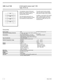
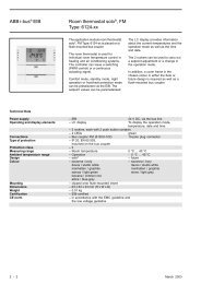
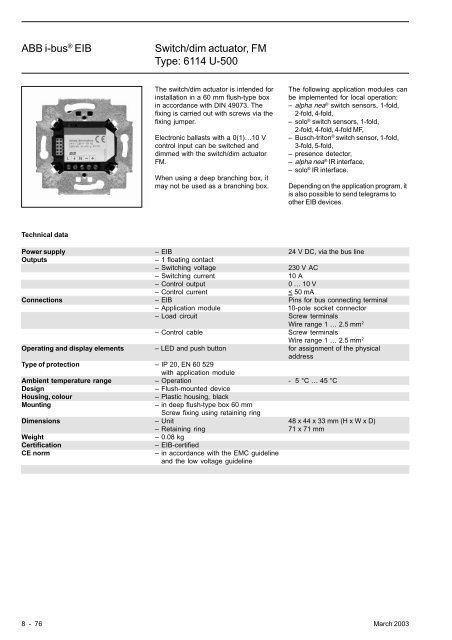
<strong>ABB</strong> i-bus ® <strong>EIB</strong><strong>Switch</strong>/<strong>dim</strong> <strong>actuator</strong>, <strong>FM</strong><strong>Type</strong>: <strong>6114</strong> U-<strong>500</strong>The switch/<strong>dim</strong> <strong>actuator</strong> is intended forinstallation in a 60 mm flush-type boxin accordance with DIN 49073. Thefixing is carried out with screws via thefixing jumper.Electronic ballasts with a 0(1)…10 Vcontrol input can be switched and<strong>dim</strong>med with the switch/<strong>dim</strong> <strong>actuator</strong><strong>FM</strong>.When using a deep branching box, itmay not be used as a branching box.The following application modules canbe implemented for local operation:– alpha nea ® switch sensors, 1-fold,2-fold, 4-fold,– solo ® switch sensors, 1-fold,2-fold, 4-fold, 4-fold MF,– Busch-triton ® switch sensor, 1-fold,3-fold, 5-fold,– presence detector,– alpha nea ® IR interface,– solo ® IR interface.Depending on the application program, itis also possible to send telegrams toother <strong>EIB</strong> devices.Technical dataPower supply – <strong>EIB</strong> 24 V DC, via the bus lineOutputs– 1 floating contact– <strong>Switch</strong>ing voltage 230 V AC– <strong>Switch</strong>ing current 10 A– Control output 0 … 10 V– Control current < 50 mAConnections – <strong>EIB</strong> Pins for bus connecting terminal– Application module 10-pole socket connector– Load circuit Screw terminalsWire range 1 … 2.5 mm 2– Control cable Screw terminalsWire range 1 … 2.5 mm 2Operating and display elements – LED and push button for assignment of the physicaladdress<strong>Type</strong> of protection – IP 20, EN 60 529with application moduleAmbient temperature range – Operation - 5 °C … 45 °CDesign– Flush-mounted deviceHousing, colour– Plastic housing, blackMounting– in deep flush-type box 60 mmScrew fixing using retaining ringDimensions – Unit 48 x 44 x 33 mm (H x W x D)– Retaining ring 71 x 71 mmWeight– 0.08 kgCertificationCE norm– <strong>EIB</strong>-certified– in accordance with the EMC guidelineand the low voltage guideline8 - 76 March 2003
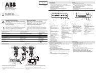
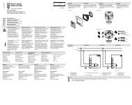
<strong>ABB</strong> i-bus ® <strong>EIB</strong><strong>Switch</strong>/<strong>dim</strong> <strong>actuator</strong>, <strong>FM</strong><strong>Type</strong>: <strong>6114</strong> U-<strong>500</strong>Application programs in ETS Number of Max. number of Max. number ofcommunication objects group addresses associationswithout operating element:<strong>Switch</strong> Dim Logic Status Fixed value /1 8 16 21Note:Please take the application programs for the alpha, solo ® and Busch-triton ® switch sensors from the table on the next page.Circuit diagram1 5234 61 230 V supply voltage 5 Electronic ballast, 0(1)…10 V2 230 V supply terminals 6 Terminals for control cable3 <strong>Switch</strong>/<strong>dim</strong> <strong>actuator</strong> <strong>FM</strong> 0(1)…10 V4 Bus connecting terminalMarch 2003 8 - 77
<strong>ABB</strong> i-bus ® <strong>EIB</strong><strong>Switch</strong>/<strong>dim</strong> <strong>actuator</strong>, <strong>FM</strong><strong>Type</strong>: <strong>6114</strong> U-<strong>500</strong>Application programs in ETS Number of Max. number of Max. number ofcommunication objects group addresses associationsFor alpha 1-fold switch sensor:<strong>Switch</strong> Dim Shutter Flex. Alloc. Logic Status /3 10 16 21For alpha 2-fold switch sensor:<strong>Switch</strong> Dim Shutter Flex. Alloc. Logic Status /2 12 16 21For alpha 4-fold switch sensor:<strong>Switch</strong> Dim Shutter Flex. Alloc. Logic Status /1 16 16 21For presence detector:<strong>Switch</strong> Dim Cyclic HVAC Bright. control /1 12 28 29For alpha infrared interface:<strong>Switch</strong> Dim Shutter Logic Status /1 20 20 20For solo ® 1-fold push button:<strong>Switch</strong> sensor 1f TP/1 15 15 15For solo ® 2-fold push button:<strong>Switch</strong> sensor 2f TP/1 15 15 15For solo ® 4-fold push button:<strong>Switch</strong> sensor 4f TP/1 15 15 15For solo ® 4-fold multi function push button:<strong>Switch</strong> sensor 4f MF TP/1 22 22 22For solo ® 3-fold push button with IR-Receiver:<strong>Switch</strong> sensor 3f IR TP/1 24 24 24Note:The application descriptions for the solo ® switch sensors in combination with the 1-fold switch <strong>actuator</strong>/sensor <strong>FM</strong> (6110 U-101)can be found directly in the descriptions for the individual sensors, in the chapter “Flush-mounted sensors”.8 - 78 March 2003
<strong>ABB</strong> i-bus ® <strong>EIB</strong><strong>Switch</strong>/<strong>dim</strong> <strong>actuator</strong>, <strong>FM</strong><strong>Type</strong>: <strong>6114</strong> U-<strong>500</strong>Application programs in ETS Number of Max. number of Max. number ofcommunication objects group addresses associationsFor 1-fold Busch-triton ® switch sensor:<strong>Switch</strong> Dim Shutter Flex. Alloc. Logic Status /4 11 11 23For 3-fold Busch-triton ® switch sensor:IR <strong>Switch</strong> Dim Shutter Lightscene /8 19 19 19For 3-fold Busch-triton ® switch sensor with display:IR LCD <strong>Switch</strong> Dim Shutter Lightscene /4 19 19 19For 5-fold Busch-triton ® switch sensor:IR <strong>Switch</strong> Dim Shutter /1 17 18 18IR <strong>Switch</strong> Dim Shutter Lightscene /4 19 19 19For 5-fold Busch-triton ® switch sensor with display:IR LCD <strong>Switch</strong> Dim Shutter /3 19 24 20IR LCD <strong>Switch</strong> Dim Shutter Lightscene /3 19 19 21March 2003 8 - 79
<strong>ABB</strong> i-bus ® <strong>EIB</strong><strong>Switch</strong>/<strong>dim</strong> <strong>actuator</strong>, <strong>FM</strong><strong>Type</strong>: <strong>6114</strong> U-<strong>500</strong><strong>Switch</strong> Dim Logic Status Fixedvalue /1Selection in ETS2– <strong>ABB</strong>IlluminationDimmer– <strong>ABB</strong><strong>FM</strong> Dimmer <strong>actuator</strong>/sensorwithout operating elementThe application program is intendedfor the flush-mounted switch/<strong>dim</strong><strong>actuator</strong> without a further applicationmodule.<strong>Switch</strong>The output can be switched on and offvia the 1 bit communication object“Dimmer - <strong>Switch</strong>ing”. The samecommunication object also sends atelegram if the output changes its statebecause e.g. the 4 bit object no. 1“Dimmer” or the 1 byte object no. 2“Dimmer” has received a telegram.If the output objects of several switch/<strong>dim</strong> <strong>actuator</strong>s use the same groupaddresses, the parameter “Operationmode by paralleling ...” must be takeninto account. Only one device may beset to “Master”. The other devices mustuse the “Slave” setting. If this is notobserved, the devices may continuallysend telegrams to each other.The brightness value, which is used bythe switch/<strong>dim</strong> <strong>actuator</strong> <strong>FM</strong> when it isswitched on, is defined in theparameters. A constant value between10% brightness and 100% brightnesscan be selected. Alternatively, the<strong>actuator</strong> stores the value of the object“Brightness value” at the point when itwas switched off via the switchingobject and then recreates it.DimThe connected luminaire can be<strong>dim</strong>med in accordance with EIS 2 withthe 4 bit communication object“Dimmer”. If the <strong>actuator</strong> is switched off,it can be <strong>dim</strong>med on via the 4 bitobject.The interval for passing through the<strong>dim</strong>ming range can be set with the twoparameters “Time base ...” and “Factor...”. The <strong>actuator</strong> uses the formulaTotal time = Base * Factor.Using the 1 byte communication objectno. 2, the luminaire can be assignedone of 256 brightness values in arange between 0 = switched off and255 = full brightness. It is defined viathe parameter “Behaviour on changein the brightness value” whether thenew value is set immediately (“jump tovalue”) or with the selected <strong>dim</strong>mingspeed (“<strong>dim</strong> to value”).StatusIf the parameter “Status response” isset to “yes”, the ETS2 programdisplays a further 1 bit object “Statusresponse”. As soon as the switch/<strong>dim</strong><strong>actuator</strong> is switched on, regardless ofthe brightness value, a telegram issent with the value “1”. If the <strong>actuator</strong> isswitched off again, a “0” is sent.LogicIt is possible to set an AND or ORfunction with the parameter “Logicalconnection”. In both cases, ETS2displays an additional communicationobject. The <strong>actuator</strong> links the values ofobjects no. 0 “<strong>Switch</strong>ing” and no. 3 “...connection” and then switches theoutput. Even in this case, theparameter “Status response” enablesprecise monitoring of the actual outputstate.Read-only memoryThe <strong>actuator</strong> has three 1 bitcommunication objects “Read-onlymemory ...”. It is possible to set up to sixvalues with the two possible objectvalues “0” and “1”. The parameters“Value for read-only memory ...” areused for this purpose. The number ofread-only memory devices that areactually in use is defined with theparameters “Number of objects” and“Behaviour receiving an OFFtelegram”.Bus voltage failure / recoveryOn bus voltage failure, the switch/<strong>dim</strong><strong>actuator</strong> <strong>FM</strong> switches off the connectedluminaires. On bus voltage recovery,the luminaires remain switched off inthe normal state. It is however alsopossible to set the minimum ormaximum brightness or the lastbrightness value that was stored priorto the voltage failure.8 - 80 March 2003
<strong>ABB</strong> i-bus ® <strong>EIB</strong><strong>Switch</strong>/<strong>dim</strong> <strong>actuator</strong>, <strong>FM</strong><strong>Type</strong>: <strong>6114</strong> U-<strong>500</strong>Communication objectsNo. <strong>Type</strong> Object name Function0 1 bit Dimmer <strong>Switch</strong>ing1 4 bit Dimmer Dimming2 1 byte Dimmer Brightness valueCommunication objectsfor logical connection, status responseand read-only memoryNo. <strong>Type</strong> Object name Function…3 1 bit Dimmer … connection4 1 bit Dimmer Status response5 1 bit Dimmer Read-only memory A / B6 1 bit Dimmer Read-only memory C / D7 1 bit Dimmer Read-only memory E / FParametersThe default setting for the valuesis printed in bold type.General:– Behaviour on change in the jump to valuebrightness value<strong>dim</strong> to value– Brightness value in event of ON final valuetelegramparameterized valueOnly if “parameterized value” is selected:– <strong>Switch</strong> ON brightness 10% brightness / 20% brightness / … /100% brightness– Brightness value at bus recovery OFFmax. brightnessmin. brightnessfinal value– Operation mode by paralleling Mastersome <strong>dim</strong>mersSlaveOperation modes:– Logical connection no logical connectionAND connectionOR connection– Status response yesnoDimming characteristic curve:– Time base for passing the <strong>dim</strong>ming 0.5 ms / 8.0 ms / 130 ms / 2.1 s / 33 srange– Factor for passing the <strong>dim</strong>ming 20range (2 … 255)For the read-only memory of the outputs:– Number of objects none / 1 / 2 / 3– Behaviour receiving an ON telegram set preselected brightness valueSeparate for each read-only memory:– Value for read-only memory … 10% brightness(object no. … = ON)20% brightness…80% brightness90% brightness100% brightness– Behaviour receiving an OFF telegram set preselected brightness valueno reactionSeparate for each read-only memory:– Value for read-only memory … 10% brightness(object no. … = OFF)20% brightness30% brightness40% brightness…90% brightness100% brightnessMarch 2003 8 - 81
<strong>ABB</strong> i-bus ® <strong>EIB</strong><strong>Switch</strong>/<strong>dim</strong> <strong>actuator</strong>, <strong>FM</strong><strong>Type</strong>: <strong>6114</strong> U-<strong>500</strong> + 6115-2x<strong>Switch</strong> Dim Shutter Flex. Alloc. LogicStatus /3Selection in ETS2– <strong>ABB</strong>Push Button alpha neaPush button, 1-fold for 1SDAThe application program is intendedfor the 1-fold switch sensor applicationmodule in connection with the switch/<strong>dim</strong> <strong>actuator</strong> <strong>FM</strong>.Note: The descriptions for– switch,– <strong>dim</strong>,– status,– logic,– read-only memory,– bus voltage failure or recoveryhave already been outlined in theapplication description “<strong>Switch</strong> DimLogic Status Fixed value /1”.The functions of the push button aredescribed in the following section.<strong>Switch</strong>If the parameter “Operation moderocker” is set to “<strong>Switch</strong>ing”, the ETS2program displays a furthercommunication object “Push button -<strong>Switch</strong>ing”. When the upper contact ofthe push button is pressed, the devicesends an “On” telegram while an “Off”telegram is sent on the <strong>EIB</strong> when thelower contact is pressed.DimIn the “Dimming” operating mode,ETS2 displays two communicationobjects for the push button for<strong>dim</strong>ming.After a short push button action, thecorresponding 1 bit communicationobject “Push button short - <strong>Switch</strong>ing”sends “On” or “Off” telegrams on the<strong>EIB</strong>.After a long operation, the push buttonsends <strong>dim</strong>ming telegrams to the 4 bitobject “Push button long - Dimming”.When the push button is released, thepush button sends the telegram “Stop<strong>dim</strong>ming”.Pressing the upper contact switcheson or <strong>dim</strong>s brighter. Pressing the lowercontact switches off or <strong>dim</strong>s darker.ShutterIf “Shutter” is selected as the operatingmode, two 1 bit communication objectsare available for the push button.After a long push button action, thecorresponding object “Push buttonlong - Move shutter” sends telegramsfor shutter movement. The object “Pushbutton short - Adjust lamella of shutter”sends “Louvre adjustment / stop”telegrams after a short push buttonaction.Pressing the upper push buttonenables the shutter to be raised i.e. thevalue “0” is sent. After pressing thelower contact, a “1” is sent and theshutter is lowered.Flexible allocationIn the operation mode “Flexibleallocation”, the push button has thetwo 1 bit communication objects“Upper push button - <strong>Switch</strong>ing” and“Lower push button - <strong>Switch</strong>ing”.With the parameters “Reaction onupper contact” or “Reaction on lowercontact”, it is defined when the pushbutton sends “On” or “Off” telegrams.By default, the push button is toggledafter each operation. With the setting“switch defined”, it can be freelyselected whether a telegram is sentwhen the push button is pressed(rising) or when it is released (falling).With the setting “no reaction”, the pushbutton is switched off.LEDWith the parameter “Operation mode ofLED”, it can be defined whether theLED displays the value of object no. 8“Push button ...” or always lights up inthe same colour as an orientation light.8 - 82 March 2003
<strong>ABB</strong> i-bus ® <strong>EIB</strong><strong>Switch</strong>/<strong>dim</strong> <strong>actuator</strong>, <strong>FM</strong><strong>Type</strong>: <strong>6114</strong> U-<strong>500</strong> + 6115-2xCommunication objectsNo. <strong>Type</strong> Object name Function0 1 bit Dimmer <strong>Switch</strong>ing1 4 bit Dimmer Dimming2 1 byte Dimmer Brightness value…8 1 bit Push button <strong>Switch</strong>ingCommunication objectsfor logical connection, status responseand read-only memoryNo. <strong>Type</strong> Object name Function…3 1 bit Dimmer … connection4 1 bit Dimmer Status response5 1 bit Dimmer Read-only memory A / B6 1 bit Dimmer Read-only memory C / D7 1 bit Dimmer Read-only memory E / F…Communication objectsfor <strong>dim</strong>ming functionNo. <strong>Type</strong> Object name Function…8 1 bit Push button short <strong>Switch</strong>ing9 4 bit Push button long DimmingCommunication objectsfor shutter functionNo. <strong>Type</strong> Object name Function…8 1 bit Push button short Move shutter9 1 bit Push button long Adjust lamella of shutterCommunication objectsfor push button functionNo. <strong>Type</strong> Object name Function…8 1 bit Lower push button <strong>Switch</strong>ing9 1 bit Upper push button <strong>Switch</strong>ingMarch 2003 8 - 83
<strong>ABB</strong> i-bus ® <strong>EIB</strong><strong>Switch</strong>/<strong>dim</strong> <strong>actuator</strong>, <strong>FM</strong><strong>Type</strong>: <strong>6114</strong> U-<strong>500</strong> + 6115-2xParameters for the switch/<strong>dim</strong><strong>actuator</strong>The default setting for the valuesis printed in bold type.General:– Behaviour on change in the jump to valuebrightness value<strong>dim</strong> to value– Brightness value in event of ON final valuetelegramparameterized valueOnly if “parameterized value” is selected:– <strong>Switch</strong> ON brightness 10% brightness / 20% brightness / … /100% brightness– Brightness value at bus recovery OFFmax. brightnessmin. brightnessfinal value– Operation mode by paralleling Mastersome <strong>dim</strong>mersSlaveOperation modes:– Logical connection no logical connectionAND connectionOR connection– Status response yesnoDimming characteristic curve:– Time base for passing the <strong>dim</strong>ming 0.5 ms / 8.0 ms / 130 ms / 2.1 s / 33 srange– Factor for passing the <strong>dim</strong>ming 20range (2 … 255)For the read-only memory of the outputs:– Number of objects none / 1 / 2 / 3– Behaviour receiving an ON telegram set preselected brightness valueSeparate for each read-only memory:– Value for read-only memory … 10% brightness(object no. … = ON)20% brightness…80% brightness90% brightness100% brightness– Behaviour receiving an OFF telegram set preselected brightness valueno reactionSeparate for each read-only memory:– Value for read-only memory … 10% brightness(object no. … = OFF)20% brightness30% brightness40% brightness…90% brightness100% brightness8 - 84 March 2003
<strong>ABB</strong> i-bus ® <strong>EIB</strong><strong>Switch</strong>/<strong>dim</strong> <strong>actuator</strong>, <strong>FM</strong><strong>Type</strong>: <strong>6114</strong> U-<strong>500</strong> + 6115-2xParameters for the push buttonThe default setting for the valuesis printed in bold type.Push button:– Operation mode rocker <strong>Switch</strong>ingDimmingShutterFlexible allocationOnly if “Flexible allocation” is selected:– Reaction on upper contact TOGGLEswitch definedOnly if “switch defined” is selected:– Value of object A no reactionrising = ONrising = OFFfalling = ONfalling = OFFrising = ON, falling = OFFrising = ON, falling = ONrising = OFF, falling = ONrising = OFF, falling = OFF– Reaction on lower contact TOGGLEswitch definedOnly if “switch defined” is selected:– Value of object B no reactionrising = ONrising = OFFfalling = ONfalling = OFFrising = ON, falling = OFFrising = ON, falling = ONrising = OFF, falling = ONrising = OFF, falling = OFF– Operation mode of LED shows object valueorientation lightOnly if “shows object value” is selected:– Colour of the LED OFF = green, ON = redOFF = red, ON = greenOnly if “orientation light” is selected:– Colour of the LED always greenalways redMarch 2003 8 - 85
<strong>ABB</strong> i-bus ® <strong>EIB</strong><strong>Switch</strong>/<strong>dim</strong> <strong>actuator</strong>, <strong>FM</strong><strong>Type</strong>: <strong>6114</strong> U-<strong>500</strong> + 6116-2x<strong>Switch</strong> Dim Shutter Flex. Alloc. LogicStatus /2Selection in ETS2– <strong>ABB</strong>Push Button alpha neaPush button, 2-fold for 1SDAThe application program is intendedfor the 2-fold switch sensor applicationmodule in connection with the switch/<strong>dim</strong> <strong>actuator</strong> <strong>FM</strong>.Note: The descriptions for– switch,– <strong>dim</strong>,– status,– logic,– read-only memory,– bus voltage failure or recoveryhave already been outlined in theapplication description “<strong>Switch</strong> DimLogic Status Fixed value /1”.The functions of the push buttons aredescribed in the following section.<strong>Switch</strong>If the parameter “Operation moderocker” is set to “<strong>Switch</strong>ing”, the ETS2program displays two furthercommunication objects “Push buttonleft - <strong>Switch</strong>ing” and “Right push button- <strong>Switch</strong>ing”. When the upper contact ofthe push button is pressed, the devicesends an “On” telegram while an “Off”telegram is sent on the <strong>EIB</strong> when thelower contact is pressed.DimIn the “Dimming” operating mode,ETS2 displays two communicationobjects for each push button for<strong>dim</strong>ming.After a short push button action, thecorresponding 1 bit communicationobject “Push button ... short -<strong>Switch</strong>ing” sends “On” or “Off”telegrams on the <strong>EIB</strong>.After a long operation, the push buttonsends <strong>dim</strong>ming telegrams to the 4 bitobject “Push button ... long - Dimming”.When the push button is released, thepush button sends the telegram “Stop<strong>dim</strong>ming”.Pressing the upper contact switcheson or <strong>dim</strong>s brighter. Pressing the lowercontact switches off or <strong>dim</strong>s darker.ShutterIf “Shutter” is selected as the operatingmode, two 1 bit communication objectsare available for each push button.After a long push button action, thecorresponding object “Push button ...long - Move shutter” sends telegramsfor shutter movement. The object “Pushbutton ... short - Adjust lamella ofshutter” sends “Louvre adjustment /stop” telegrams after a short pushbutton action.Pressing the upper push buttonenables the shutter to be raised i.e. thevalue “0” is sent. After pressing thelower contact, a “1” is sent and theshutter is lowered.Flexible allocationIn the operation mode “Flexibleallocation”, the push button has the1 bit communication objects “Leftupper push button - <strong>Switch</strong>ing”, “Leftpush button lower - <strong>Switch</strong>ing”, “Rightpush button upper - <strong>Switch</strong>ing” and“Right push button lower - <strong>Switch</strong>ing”.With the parameters “Reaction onupper contact” or “Reaction on lowercontact”, it is defined when the pushbutton sends “On” or “Off” telegrams.By default, the push button is toggledafter each operation. With the setting“switch defined”, it can be freelyselected whether a telegram is sentwhen the push button is pressed(rising) or when it is released (falling).With the setting “no reaction”, the pushbutton is switched off.LEDWith the parameter “Operation mode ofLED”, it can be defined whether theLED displays the value of object no. 8/10 “Push button ...” or always lights upin the same colour as an orientationlight.8 - 86 March 2003
<strong>ABB</strong> i-bus ® <strong>EIB</strong><strong>Switch</strong>/<strong>dim</strong> <strong>actuator</strong>, <strong>FM</strong><strong>Type</strong>: <strong>6114</strong> U-<strong>500</strong> + 6116-2xCommunication objectsNo. <strong>Type</strong> Object name Function0 1 bit Dimmer <strong>Switch</strong>ing1 4 bit Dimmer Dimming2 1 byte Dimmer Brightness value…8 1 bit Push button left <strong>Switch</strong>ing10 1 bit Right push button <strong>Switch</strong>ingCommunication objectsfor logical connection, status responseand read-only memoryNo. <strong>Type</strong> Object name Function…3 1 bit Dimmer … connection4 1 bit Dimmer Status response5 1 bit Dimmer Read-only memory A / B6 1 bit Dimmer Read-only memory C / D7 1 bit Dimmer Read-only memory E / F…Communication objectsfor <strong>dim</strong>ming functionNo. <strong>Type</strong> Object name Function…8 1 bit Push button left short <strong>Switch</strong>ing9 4 bit Push button left long Dimming10 1 bit Push button right short <strong>Switch</strong>ing11 4 bit Push button right long DimmingCommunication objectsfor shutter functionNo. <strong>Type</strong> Object name Function…8 1 bit Push button left short Move shutter9 1 bit Push button left long Adjust lamella of shutter10 1 bit Push button right short Move shutter11 1 bit Push button right long Adjust lamella of shutterCommunication objectsfor push button functionNo. <strong>Type</strong> Object name Function…8 1 bit Left push button lower <strong>Switch</strong>ing9 1 bit Left upper push button <strong>Switch</strong>ing10 1 bit Right push button lower <strong>Switch</strong>ing11 1 bit Right push button upper <strong>Switch</strong>ingMarch 2003 8 - 87
<strong>ABB</strong> i-bus ® <strong>EIB</strong><strong>Switch</strong>/<strong>dim</strong> <strong>actuator</strong>, <strong>FM</strong><strong>Type</strong>: <strong>6114</strong> U-<strong>500</strong> + 6116-2xParameters for the switch/<strong>dim</strong><strong>actuator</strong>The default setting for the valuesis printed in bold type.General:– Behaviour on change in the jump to valuebrightness value<strong>dim</strong> to value– Brightness value in event of ON final valuetelegramparameterized valueOnly if “parameterized value” is selected:– <strong>Switch</strong> ON brightness 10% brightness / 20% brightness / … /100% brightness– Brightness value at bus recovery OFFmax. brightnessmin. brightnessfinal value– Operation mode by paralleling Mastersome <strong>dim</strong>mersSlaveOperation modes:– Logical connection no logical connectionAND connectionOR connection– Status response yesnoDimming characteristic curve:– Time base for passing the <strong>dim</strong>ming 0.5 ms / 8.0 ms / 130 ms / 2.1 s / 33 srange– Factor for passing the <strong>dim</strong>ming 20range (2 … 255)For the read-only memory of the outputs:– Number of objects none / 1 / 2 / 3– Behaviour receiving an ON telegram set preselected brightness valueSeparate for each read-only memory:– Value for read-only memory … 10% brightness(object no. … = ON)20% brightness…80% brightness90% brightness100% brightness– Behaviour receiving an OFF telegram set preselected brightness valueno reactionSeparate for each read-only memory:– Value for read-only memory … 10% brightness(object no. … = OFF)20% brightness30% brightness40% brightness…90% brightness100% brightness8 - 88 March 2003
<strong>ABB</strong> i-bus ® <strong>EIB</strong><strong>Switch</strong>/<strong>dim</strong> <strong>actuator</strong>, <strong>FM</strong><strong>Type</strong>: <strong>6114</strong> U-<strong>500</strong> + 6116-2xParameters for the push buttonThe default setting for the valuesis printed in bold type.Separate for each push button:– Operation mode rocker <strong>Switch</strong>ingDimmingShutterFlexible allocationOnly if “Flexible allocation” is selected:– Reaction on upper contact TOGGLEswitch definedOnly if “switch defined” is selected:– Value of object A no reactionrising = ONrising = OFFfalling = ONfalling = OFFrising = ON, falling = OFFrising = ON, falling = ONrising = OFF, falling = ONrising = OFF, falling = OFF– Reaction on lower contact TOGGLEswitch definedOnly if “switch defined” is selected:– Value of object B no reactionrising = ONrising = OFFfalling = ONfalling = OFFrising = ON, falling = OFFrising = ON, falling = ONrising = OFF, falling = ONrising = OFF, falling = OFF– Operation mode of LED shows object valueorientation lightOnly if “shows object value” is selected:– Colour of the LED OFF = green, ON = redOFF = red, ON = greenOnly if “orientation light” is selected:– Colour of the LED always greenalways redMarch 2003 8 - 89
<strong>ABB</strong> i-bus ® <strong>EIB</strong><strong>Switch</strong>/<strong>dim</strong> <strong>actuator</strong>, <strong>FM</strong><strong>Type</strong>: <strong>6114</strong> U-<strong>500</strong> + 6117-2x<strong>Switch</strong> Dim Shutter Flex. Alloc. LogicStatus /1Selection in ETS2– <strong>ABB</strong>Push Button alpha neaPush button, 4-fold for 1SDAThe application program is intendedfor the 4-fold switch sensor applicationmodule in connection with the switch/<strong>dim</strong> <strong>actuator</strong> <strong>FM</strong>.Note: The descriptions for– switch,– <strong>dim</strong>,– status,– logic,– read-only memory,– bus voltage failure or recoveryhave already been outlined in theapplication description “<strong>Switch</strong> DimLogic Status Fixed value /1”.The functions of the push buttons aredescribed in the following section.<strong>Switch</strong>If the parameter “Operation moderocker” is set to “<strong>Switch</strong>ing”, the ETS2program displays the communicationobjects “Push button ... - <strong>Switch</strong>ing”.When the upper contact of the pushbutton is pressed, the device sends an“On” telegram while an “Off” telegramis sent on the <strong>EIB</strong> when the lowercontact is pressed.DimIn the “Dimming” operating mode,ETS2 displays two communicationobjects for each push button for<strong>dim</strong>ming.After a short push button action, thecorresponding 1 bit communicationobject “Push button ... short -<strong>Switch</strong>ing” sends “On” or “Off”telegrams on the <strong>EIB</strong>.After a long operation, the push buttonsends <strong>dim</strong>ming telegrams to the 4 bitobject “Push button ... long - Dimming”.When the push button is released, thepush button sends the telegram “Stop<strong>dim</strong>ming”.Pressing the upper contact switcheson or <strong>dim</strong>s brighter. Pressing the lowercontact switches off or <strong>dim</strong>s darker.ShutterIf “Shutter” is selected as the operatingmode, two 1 bit communication objectsare available for each push button.After a long push button action, thecorresponding object “Push button ...long - Move shutter” sends telegramsfor shutter movement. The object “Pushbutton ... short - Adjust lamella ofshutter” sends “Louvre adjustment /stop” telegrams after a short pushbutton action.Pressing the upper push buttonenables the shutter to be raised i.e. thevalue “0” is sent. After pressing thelower contact, a “1” is sent and theshutter is lowered.Flexible allocationIn the operation mode “Flexibleallocation”, each push button has two1 bit communication objects available.With the parameters “Reaction onupper contact” or “Reaction on lowercontact”, it is defined when the pushbutton sends “On” or “Off” telegrams.By default, the push button is toggledafter each operation. With the setting“switch defined”, it can be freelyselected whether a telegram is sentwhen the push button is pressed(rising) or when it is released (falling).With the setting “no reaction”, the pushbutton is switched off.LEDWith the parameter “Operation mode ofLED”, it can be defined whether theLED displays the value of object no. 8/10/12/14 “Push button ...” or alwayslights up in the same colour as anorientation light.8 - 90 March 2003
<strong>ABB</strong> i-bus ® <strong>EIB</strong><strong>Switch</strong>/<strong>dim</strong> <strong>actuator</strong>, <strong>FM</strong><strong>Type</strong>: <strong>6114</strong> U-<strong>500</strong> + 6117-2xCommunication objectsNo. <strong>Type</strong> Object name Function0 1 bit Dimmer <strong>Switch</strong>ing1 4 bit Dimmer Dimming2 1 byte Dimmer Brightness value…8 1 bit Push button left <strong>Switch</strong>ing10 1 bit Push button left middle <strong>Switch</strong>ing12 1 bit Right middle button <strong>Switch</strong>ing14 1 bit Right push button <strong>Switch</strong>ingCommunication objectsfor logical connection, status responseand read-only memoryNo. <strong>Type</strong> Object name Function…3 1 bit Dimmer … connection4 1 bit Dimmer Status response5 1 bit Dimmer Read-only memory A / B6 1 bit Dimmer Read-only memory C / D7 1 bit Dimmer Read-only memory E / F…Communication objectsfor <strong>dim</strong>ming functionNo. <strong>Type</strong> Object name Function…8 1 bit Push button left short <strong>Switch</strong>ing9 4 bit Push button left long Dimming10 1 bit Push button left middle short <strong>Switch</strong>ing11 4 bit Push button left middle long Dimming12 1 bit Push button right middle short <strong>Switch</strong>ing13 4 bit Push button right middle long Dimming14 1 bit Push button right short <strong>Switch</strong>ing15 4 bit Push button right long DimmingCommunication objectsfor shutter functionNo. <strong>Type</strong> Object name Function…8 1 bit Push button left long Move shutter9 1 bit Push button left short Adjust lamella of shutter10 1 bit Push button left middle long Move shutter11 1 bit Push button left middle short Adjust lamella of shutter12 1 bit Push button right middle long Move shutter13 1 bit Push button right middle short Adjust lamella of shutter14 1 bit Push button right long Move shutter15 1 bit Push button right short Adjust lamella of shutterCommunication objectsfor push button functionNo. <strong>Type</strong> Object name Function…8 1 bit Left push button lower <strong>Switch</strong>ing9 1 bit Left upper push button <strong>Switch</strong>ing10 1 bit Push button left middle lower <strong>Switch</strong>ing11 1 bit Push button left middle upper <strong>Switch</strong>ing12 1 bit Right middle lower button <strong>Switch</strong>ing13 1 bit Right middle upper button <strong>Switch</strong>ing14 1 bit Right push button lower <strong>Switch</strong>ing15 1 bit Right push button upper <strong>Switch</strong>ingMarch 2003 8 - 91
<strong>ABB</strong> i-bus ® <strong>EIB</strong><strong>Switch</strong>/<strong>dim</strong> <strong>actuator</strong>, <strong>FM</strong><strong>Type</strong>: <strong>6114</strong> U-<strong>500</strong> + 6117-2xParameters for the switch/<strong>dim</strong><strong>actuator</strong>The default setting for the valuesis printed in bold type.General:– Behaviour on change in the jumpt to valuebrightness value<strong>dim</strong> to value– Brightness value in event of ON final valuetelegramparameterized valueOnly if “parameterized value” is selected:– <strong>Switch</strong> ON brightness 10% brightness / 20% brightness / … /100% brightness– Brightness value at bus recovery OFFmax. brightnessmin. brightnessfinal value– Operation mode by paralleling Mastersome <strong>dim</strong>mersSlaveOperation modes:– Logical connection no logical connectionAND connectionOR connection– Status response yesnoDimming characteristic curve:– Time base for passing the <strong>dim</strong>ming 0.5 ms / 8.0 ms / 130 ms / 2.1 s / 33 srange– Factor for passing the <strong>dim</strong>ming 20range (2 … 255)For the read-only memory of the outputs:– Number of objects none / 1 / 2 / 3– Behaviour receiving an ON telegram set preselected brightness valueSeparate for each read-only memory:– Value for read-only memory … 10% brightness(object no. … = ON)20% brightness…80% brightness90% brightness100% brightness– Behaviour receiving an OFF telegram set preselected brightness valueno reactionSeparate for each read-only memory:– Value for read-only memory … 10% brightness(object no. … = OFF)20% brightness30% brightness40% brightness…90% brightness100% brightness8 - 92 March 2003
<strong>ABB</strong> i-bus ® <strong>EIB</strong><strong>Switch</strong>/<strong>dim</strong> <strong>actuator</strong>, <strong>FM</strong><strong>Type</strong>: <strong>6114</strong> U-<strong>500</strong> + 6117-2xParameters for the push buttonThe default setting for the valuesis printed in bold type.Separate for each push button:– Operation mode rocker <strong>Switch</strong>ingDimmingShutterFlexible allocationOnly if “Flexible allocation” is selected:– Reaction on upper contact TOGGLEswitch definedOnly if “switch defined” is selected:– Value of object A no reactionrising = ONrising = OFFfalling = ONfalling = OFFrising = ON, falling = OFFrising = ON, falling = ONrising = OFF, falling = ONrising = OFF, falling = OFF– Reaction on lower contact TOGGLEswitch definedOnly if “switch defined” is selected:– Value of object B no reactionrising = ONrising = OFFfalling = ONfalling = OFFrising = ON, falling = OFFrising = ON, falling = ONrising = OFF, falling = ONrising = OFF, falling = OFF– Operation mode of LED shows object valueorientation lightOnly if “shows object value” is selected:– Colour of the LED OFF = green, ON = redOFF = red, ON = greenOnly if “orientation light” is selected:– Colour of the LED always greenalways redMarch 2003 8 - 93
<strong>ABB</strong> i-bus ® <strong>EIB</strong><strong>Switch</strong>/<strong>dim</strong> <strong>actuator</strong>, <strong>FM</strong><strong>Type</strong>: <strong>6114</strong> U-<strong>500</strong> + 6131-74-101<strong>Switch</strong> Dim Cyclic HVAC Bright.control /1Selection in ETS2– <strong>ABB</strong>Phys. SensorsPresence detectorThe application program is intendedfor the presence detector in connectionwith the switch/<strong>dim</strong> <strong>actuator</strong> <strong>FM</strong>.Note: The descriptions for– switch,– value,– cyclic,– setting of the channels,– brightness-dependent switching,– light source,– HVAC– and monitoringhave already been outlined in theapplication description “<strong>Switch</strong> ValueCyclic HVAC Monitoring” for thepresence detector.The function of the switch/<strong>dim</strong> <strong>actuator</strong>and the constant brightness controllerare described in the following section.<strong>Switch</strong>/<strong>dim</strong> <strong>actuator</strong>The output can be switched on and offvia the 1 bit communication object“Output - <strong>Switch</strong>ing”. The samecommunication object also sends atelegram if the output modifies its statebecause e.g. the 4 bit object “Dimmer -Rel. <strong>dim</strong>ming” or the 1 byte object“Dimmer - Brightness value” hasreceived a telegram. The transmit flagmust be set however.The brightness value which the switch/<strong>dim</strong> <strong>actuator</strong> uses when switching onis defined in the parameters. Ifrequired, it is possible to send a selecta constant value between 10%brightness and 100% brightness.With the 4 bit communication object“Dimmer - Rel. <strong>dim</strong>ming”, theconnected luminaires can be <strong>dim</strong>medin accordance with EIS 2. If the<strong>actuator</strong> is switched off, it can be<strong>dim</strong>med on via the 4 bit object.With the 1 byte communication object“Dimmer - Brightness value”, one of256 brightness values in a rangebetween 0 = switched off and 255 = fullbrightness can be given to theconnected luminaire. The object canalso forward a modified brightnessvalue to other <strong>dim</strong>mers. To do so, thetransmit flag must be set. The setting“internal and external <strong>dim</strong>mer” sets thetransmit flag automatically.Constant brightnessThe constant brightness controller caninfluence one or several <strong>dim</strong>ming<strong>actuator</strong>s. If only the switch/<strong>dim</strong><strong>actuator</strong> <strong>FM</strong>, which is placed on thepresence detector, is used to controlthe brightness level, the setting“internal <strong>dim</strong>mer” should be selectedas the “<strong>Type</strong> of <strong>dim</strong>ming <strong>actuator</strong>”. Ifseveral <strong>dim</strong>ming <strong>actuator</strong>s control thebrightness in the room, the selectionshould be modified to “internal andexternal <strong>dim</strong>mer”. In the latter setting,the current brightness value is sent viathe communication object “Dimmer -Brightness value”. It should be ensuredthat the <strong>dim</strong>ming <strong>actuator</strong>s that areused in this case have entered thesame group address for the brightnessobject. The <strong>dim</strong>ming <strong>actuator</strong>s must beoperated in slave mode. The setting iscarried out via the respective <strong>dim</strong>merapplication.To avoid fluctuations in the brightnesslevel, the presence detector shouldrecord the exact area that isilluminated by the luminaires whichare controlled by the switch/<strong>dim</strong><strong>actuator</strong> <strong>FM</strong>.The constant brightness controller canbe activated or deactivated at any timevia the <strong>EIB</strong>. The object “Constantbrightness controller - Activation“ isused for this purpose. If a telegram withthe value “1” is received at this object,the constant brightness controller isswitched on. The controller is switchedoff when a telegram with the value “0”is sent to the object.If the constant brightness controllershould be switched on directly e.g. ondetection of movement, the objects“Movement - Telegr. switch” and“Constant brightness controller -Activation” should be linked togethervia a common group address.The switch/<strong>dim</strong> <strong>actuator</strong> is switched onvia the 1 bit object “Output - <strong>Switch</strong>ing”.The initial brightness value can be set.By default, the <strong>actuator</strong> switches onwith 50% brightness.The parameter “Speed of control”specifies the period that the controllerrequires to pass through the complete<strong>dim</strong>ming range. A constant level ofbrightness is more pleasing to thehuman eye. Rapid variations in thebrightness level are disruptive.8 - 94 March 2003
<strong>ABB</strong> i-bus ® <strong>EIB</strong><strong>Switch</strong>/<strong>dim</strong> <strong>actuator</strong>, <strong>FM</strong><strong>Type</strong>: <strong>6114</strong> U-<strong>500</strong> + 6131-74-101It is advisable during normal operationto leave the speed in the defaultsetting of “normal”.The value for the constant brightnesscontroller can be selected with theLux1 potentiometer of the presencedetector or via the ETS software. If thesetpoint adjustment is carried out viaETS, it is possible to enter a setpointfor the constant brightness controllerdirectly. This can be a brightness valuebetween 5 and 1000 luxn. It is howevera better idea to let the user set therequired brightness value directly. Todo so, the ETS2 program enables thecommunication object “Constantbrightness controller - Save act.brightness value”. As soon as atelegram with the value “1” is receivedat this object, the presence detectoradopts the current brightness value asthe new setpoint for the constantbrightness controller.A new setpoint for the constantbrightness controller can be assignedat any time via the 1 bytecommunication object “Constantbrightness controller - Brightnesssetpoint/act. value” (see example).If the user leaves the room, thepresence detector starts its normalrecovery time which can be set on thetab “Adjustments channel 1”. However,if the user has previously adapted thebrightness value to his requirementsvia the <strong>dim</strong>ming objects, the presencedetector starts the recovery time for aninactive constant brightness controller,once the normal recovery time haselapsed. This means that if someoneenters the room during this period, thecombined presence detector andswitch/<strong>dim</strong> <strong>actuator</strong> will not directlystart the constant brightness controller.The switch/<strong>dim</strong> <strong>actuator</strong> will switch onwith the last active brightness value.The presence detector can switch onor disable the constant brightnesscontroller mode directly after busvoltage recovery. There is acorresponding option on the “General”page.The current “Brightness setpoint/act.value” is not stored after a bus voltagefailure. If a specific brightness valueshould be set after bus voltagerecovery, it should be sent again to theobject “Constant brightness controller -Brightness setpoint/act. value”.Example:A constant brightness controller shouldbe used in a sports hall for energysaving. In leisure mode, the lightingshould be regulated to a brightnesslevel of 200 lux while in competitionmode the brightness should beregulated to <strong>500</strong> lux.The presence detector is usedtogether with the switch/<strong>dim</strong> <strong>actuator</strong><strong>FM</strong> and a 1-fold switch sensor(application “Value”) to toggle the twotypes of constant brightness control.The combined presence detector andswitch/<strong>dim</strong> <strong>actuator</strong> must be installedin a suitable position and put intooperation. After the commissioningstage, the illuminance should bedetermined with a measuring device.The current brightness value of the<strong>actuator</strong> can be modified via the<strong>dim</strong>ming objects until an illuminance of200 lux is achieved.The communication object “Constantbrightness controller - Brightnesssetpoint/act. value” must then be readout with the help of ETS2. To do so,select “Groups” from the “Test” menuand enter the group address in the“Read value” tab which has beenentered in the communication objectabove. You should then either writedown the value which is sent in theresponse or store it directly in theparameter window of the 1-fold switchsensor.Dim the <strong>actuator</strong> up again until a valueof <strong>500</strong> lux is reached. You should againsend a read request to the object“Constant brightness controller -Brightness setpoint/act. value”. Writedown the value of the responsetelegram again or enter it directly in theparameters of the 1-fold switch sensor.If you have not already done so, enterthe two recorded values in theparameter window of the 1-fold switchsensor. When selecting the applicationof the switch sensor, it should beensured that the rockers can send1 byte values.Put the switch sensor into operationand constant brightness control isimplemented with the toggling of twooperating modes.March 2003 8 - 95
<strong>ABB</strong> i-bus ® <strong>EIB</strong><strong>Switch</strong>/<strong>dim</strong> <strong>actuator</strong>, <strong>FM</strong><strong>Type</strong>: <strong>6114</strong> U-<strong>500</strong> + 6131-74-101Additional communication objectsfor switch/<strong>dim</strong> <strong>actuator</strong> <strong>FM</strong>No. <strong>Type</strong> Object name Function…6 1 bit Output <strong>Switch</strong>ing7 4 bit Dimmer Rel. <strong>dim</strong>ming8 1 byte Dimmer Brightness value9 1 bit Constant brightness controller Activation11 1 byte Constant brightness controller Brightness setpoint/act. valueCommunication objectswith object for storing the currentbrightness valueNo. <strong>Type</strong> Object name Function…10 1 bit Constant brightness controller Save act. brightness value…Parameters for “Low Access”The default setting for the valuesis printed in bold type.Parameters for “High Access”The default setting for the valuesis printed in bold type.Constant brightness controllerwith “Low Access”:– <strong>Type</strong> of <strong>dim</strong>ming <strong>actuator</strong> internal and external <strong>dim</strong>merinternal <strong>dim</strong>mer– Activation object constant brightness not availablecontrolavailableOnly if activation object is available:– enabling constant brightness ON telegramcontrol atOFF telegram– <strong>Switch</strong> ON brightness 10% brightness / … / 50% brightness /… / 100% brightness– Speed of control Test mode (8.2ms*30)fast (8.2ms*50)normal (130ms*7)slow(130ms*14)General:Behaviour on bus voltage recovery(communication objects)– Constant brightness controller disabledenabledAdditional parameters for “High Access”:– Setpoint adjustable with ETSLux1 potentiometerOnly if “ETS” is selected:– Setpoint brightness control 5(5 lux … 1000 lux)– Recovery time of inactive constant ETSbrightness controller is adjusted by Illumination potentiometerOnly if “ETS” is selected:– Time base of recovery time 0.5 ms / 8.2 ms / 130 ms / 2.1 s / 34 s /9 min– Time factor of recovery time 1008 - 96 March 2003
<strong>ABB</strong> i-bus ® <strong>EIB</strong><strong>Switch</strong>/<strong>dim</strong> <strong>actuator</strong>, <strong>FM</strong><strong>Type</strong>: <strong>6114</strong> U-<strong>500</strong> + 6131-74-101March 2003 8 - 97
<strong>ABB</strong> i-bus ® <strong>EIB</strong><strong>Switch</strong>/<strong>dim</strong> <strong>actuator</strong>, <strong>FM</strong><strong>Type</strong>: <strong>6114</strong> U-<strong>500</strong> + 6135-2x<strong>Switch</strong> Dim Shutter Logic Status /1Selection in ETS2– <strong>ABB</strong>Push Button alpha neaPush button, 1-fold for 1SDAThe application program is intendedfor the infrared interface applicationmodule in connection with the switch/<strong>dim</strong> <strong>actuator</strong> <strong>FM</strong>.Note: The descriptions for– switch,– <strong>dim</strong>,– status,– logic,– read-only memory,– bus voltage failure or recoveryhave already been outlined in theapplication description “<strong>Switch</strong> DimLogic Status Fixed value /1”.The functions of the rocker pair for IRremote control or the local push buttonare described in the following section.<strong>Switch</strong>If the parameter “Operation moderocker” of one rocker pair or the localpush button is set to “<strong>Switch</strong>ing”, theETS2 program displays acommunication object “Rocker pair ... -<strong>Switch</strong>ing”. If a rocker pair is pressed,the corresponding communicationobject sends switching telegrams.DimIn the “Dimming” operating mode,ETS2 displays two communicationobjects for the rocker pairs for<strong>dim</strong>ming.After a short push button action, thecorresponding 1 bit communicationobject “Rocker pair ... short - <strong>Switch</strong>ing”sends “On” or “Off” telegrams on the<strong>EIB</strong>.After a long push button action,<strong>dim</strong>ming telegrams are sent to the 4 bitobject “Rocker pair ... long - Dimming”.When a rocker pair is released, a “Stop<strong>dim</strong>ming” telegram is sent.ShutterIf “Shutter” is selected as the operatingmode, two 1 bit communication objectsare available for the rocker pair.After a long push button action, thecorresponding object “Rocker pair ...long - Move shutter” sends telegramsfor shutter movement. The object“Rocker pair ... short - Adjust lamella ofshutter” sends “Louvre adjustment /stop” telegrams after a short pushbutton action.8 - 98 March 2003
<strong>ABB</strong> i-bus ® <strong>EIB</strong><strong>Switch</strong>/<strong>dim</strong> <strong>actuator</strong>, <strong>FM</strong><strong>Type</strong>: <strong>6114</strong> U-<strong>500</strong> + 6135-2xCommunication objectsNo. <strong>Type</strong> Object name Function0 1 bit Dimmer <strong>Switch</strong>ing1 4 bit Dimmer Dimming2 1 byte Dimmer Brightness value…8 1 bit Rocker pair 1 <strong>Switch</strong>ing10 1 bit Rocker pair 2 <strong>Switch</strong>ing12 1 bit Rocker pair 3 <strong>Switch</strong>ing14 1 bit Rocker pair 4 <strong>Switch</strong>ing16 1 bit Rocker pair 5 <strong>Switch</strong>ing18 1 bit Push button local <strong>Switch</strong>ingCommunication objectsfor logical connection, status responseand read-only memoryNo. <strong>Type</strong> Object name Function…3 1 bit Dimmer … connection4 1 bit Dimmer Status response5 1 bit Dimmer Read-only memory A / B6 1 bit Dimmer Read-only memory C / D7 1 bit Dimmer Read-only memory E / F…Communication objectsfor <strong>dim</strong>ming functionNo. <strong>Type</strong> Object name Function…8 1 bit Rocker pair 1 short <strong>Switch</strong>ing9 4 bit Rocker pair 1 long Dimming10 1 bit Rocker pair 2 short <strong>Switch</strong>ing11 4 bit Rocker pair 2 long Dimming12 1 bit Rocker pair 3 short <strong>Switch</strong>ing13 4 bit Rocker pair 3 long Dimming14 1 bit Rocker pair 4 short <strong>Switch</strong>ing15 4 bit Rocker pair 4 long Dimming16 1 bit Rocker pair 5 short <strong>Switch</strong>ing17 4 bit Rocker pair 5 long Dimming18 1 bit Push button local short <strong>Switch</strong>ing19 4 bit Push button local long DimmingCommunication objectsfor shutter functionNo. <strong>Type</strong> Object name Function…8 1 bit Rocker pair 1 short Move shutter9 1 bit Rocker pair 1 long Adjust lamella of shutter10 1 bit Rocker pair 2 short Move shutter11 1 bit Rocker pair 2 long Adjust lamella of shutter12 1 bit Rocker pair 3 short Move shutter13 1 bit Rocker pair 3 long Adjust lamella of shutter14 1 bit Rocker pair 4 short Move shutter15 1 bit Rocker pair 4 long Adjust lamella of shutter16 1 bit Rocker pair 5 short Move shutter17 1 bit Rocker pair 5 long Adjust lamella of shutter18 1 bit Push button local short Move shutter19 1 bit Push button local long Adjust lamella of shutterMarch 2003 8 - 99
<strong>ABB</strong> i-bus ® <strong>EIB</strong><strong>Switch</strong>/<strong>dim</strong> <strong>actuator</strong>, <strong>FM</strong><strong>Type</strong>: <strong>6114</strong> U-<strong>500</strong> + 6135-2xParameters for the switch/<strong>dim</strong><strong>actuator</strong>The default setting for the valuesis printed in bold type.Parameters for the push buttonThe default setting for the valuesis printed in bold type.General:– Brightness value in event of ON final valuetelegramparameterized valueOnly if “parameterized value” is selected:– <strong>Switch</strong> ON brightness 10% brightness / 20% brightness / … /100% brightness– Brightness value at bus recovery OFFmax. brightnessmin. brightnessfinal value– Operation mode by paralleling Mastersome <strong>dim</strong>mersSlaveOperation modes:– Logical connection no logical connectionAND connectionOR connection– Status response yesnoDimming characteristic curve:– Time base for passing the <strong>dim</strong>ming 0.5 ms / 8.0 ms / 130 ms / 2.1 s / 33 srange– Factor for passing the <strong>dim</strong>ming 20range (2 … 255)For the read-only memory of the outputs:– Number of objects none / 1 / 2 / 3– Behaviour receiving an ON telegram set preselected brightness valueSeparate for each read-only memory:– Value for read-only memory … 10% brightness(object no.. … = ON)20% brightness…80% brightness90% brightness100% brightness– Behaviour receiving an OFF telegram preselected brightness valueno reactionSeparate for each read-only memory:– Value for read-only memory … 10% brightness(object no. … = OFF)20% brightness30% brightness40% brightness…90% brightness100% brightnessSeparate for each rocker pair:– Operation mode rocker <strong>Switch</strong>ingDimmingShutter8 - 100 March 2003
<strong>ABB</strong> i-bus ® <strong>EIB</strong><strong>Switch</strong>/<strong>dim</strong> <strong>actuator</strong>, <strong>FM</strong><strong>Type</strong>: <strong>6114</strong> U-<strong>500</strong> + 6135-2xMarch 2003 8 - 101
<strong>ABB</strong> i-bus ® <strong>EIB</strong><strong>Switch</strong>/<strong>dim</strong> <strong>actuator</strong>, <strong>FM</strong><strong>Type</strong>: <strong>6114</strong> U-<strong>500</strong> + 6321-xx<strong>Switch</strong> Dim Shutter Flex. Alloc. LogicStatus /4Selection in ETS2– <strong>ABB</strong>Push Button tritonPush button, 1-fold for 1SDAThe application program is intendedfor the 1-fold Busch-triton ® switchsensor application module inconnection with the switch/<strong>dim</strong><strong>actuator</strong> <strong>FM</strong>.Note: The descriptions for– switch,– <strong>dim</strong>,– status,– logic,– read-only memory,– bus voltage failure or recoveryhave already been outlined in theapplication description “<strong>Switch</strong> DimLogic Status Fixed value /1”.The functions of the push button aredescribed in the following section.<strong>Switch</strong>If the parameter “Operation moderocker” is set to “<strong>Switch</strong>ing”, the ETS2program displays a communicationobject “Push button - <strong>Switch</strong>ing”. Thedevice sends an “On” telegram whenany contact of the push button ispressed while an “Off” telegram is senton the <strong>EIB</strong> when the push button ispressed again.DimIn the “Dimming” operating mode,ETS2 displays two communicationobjects for the push button for<strong>dim</strong>ming.After a short push button action, thecorresponding 1 bit communicationobject “Push button short - <strong>Switch</strong>ing”sends “On” or “Off” telegrams on the<strong>EIB</strong>.After a long operation, the push buttonsends <strong>dim</strong>ming telegrams to the 4 bitobject “Push button long - Dimming”.When the push button is released, thepush button sends the telegram “Stop<strong>dim</strong>ming”.Pressing the left push button triggers“Dimming brighter” telegrams whilepressing the right push button sends“Dimming darker” telegrams.ShutterIf “Shutter” is selected as the operatingmode, two 1 bit communication objectsare available for the push button.After a long push button action, thecorresponding object “Push buttonlong - Move shutter” sends telegramsfor shutter movement. The object “Pushbutton short - Adjust lamella of shutter”sends “Louvre adjustment / stop”telegrams after a short push buttonaction.Pressing the left push button enablesthe shutter to be raised i.e. the value“0” is sent. After pressing the right pushbutton, a “1” is sent and the shutter islowered.Flexible allocationIn the operating mode “Flexibleallocation”, the push button has thetwo 1 bit communication objects “Pushbutton left - <strong>Switch</strong>ing” and “Right pushbutton - <strong>Switch</strong>ing”.With the parameters “Reaction oncontact left” and “Reaction on contactright”, it is defined when the pushbutton sends “On” or “Off” telegrams.By default, the push button is toggledafter each operation. With the setting“switch defined”, it can be freelyselected whether a telegram is sentwhen the push button is pressed(rising) or released (falling). In thesetting “no reaction”, the push button isswitched off.Backlighting/LEDWith the parameter “Operation mode ofLED”, it can be defined whether theLED displays the value of object no. 8“Push button ...” or always lights up inthe same colour as an orientation light.The backlighting for the text field canbe switched on or off via thecommunication object “Backlighting/LED - <strong>Switch</strong>ing”. It is possible topermanently enable or disable thebacklighting via the parameter“Backlighting”.8 - 102 March 2003
<strong>ABB</strong> i-bus ® <strong>EIB</strong><strong>Switch</strong>/<strong>dim</strong> <strong>actuator</strong>, <strong>FM</strong><strong>Type</strong>: <strong>6114</strong> U-<strong>500</strong> + 6321-xxCommunication objectsNo. <strong>Type</strong> Object name Function0 1 bit Dimmer <strong>Switch</strong>ing1 4 bit Dimmer Dimming2 1 byte Dimmer Brightness value…8 1 bit Push button <strong>Switch</strong>ing10 1 bit Backlighting/LED <strong>Switch</strong>ingCommunication objectsfor logical connection, status responseand read-only memoryCommunication objectsfor <strong>dim</strong>ming functionCommunication objectsfor shutter functionCommunication objectsfor push button functionNo. <strong>Type</strong> Object name Function…3 1 bit Dimmer … connection4 1 bit Dimmer Status response5 1 bit Dimmer Read-only memory A / B6 1 bit Dimmer Read-only memory C / D7 1 bit Dimmer Read-only memory E / F…No. <strong>Type</strong> Object name Function…8 1 bit Push button short <strong>Switch</strong>ing9 4 bit Push button long Dimming10 1 bit Backlighting/LED <strong>Switch</strong>ingNo. <strong>Type</strong> Object name Function…8 1 bit Push button short Move shutter9 1 bit Push button long Adjust lamella of shutter10 1 bit Backlighting/LED <strong>Switch</strong>ingNo. <strong>Type</strong> Object name Function…8 1 bit Push button left <strong>Switch</strong>ing9 1 bit Right push button <strong>Switch</strong>ing10 1 bit Backlighting/LED <strong>Switch</strong>ingMarch 2003 8 - 103
<strong>ABB</strong> i-bus ® <strong>EIB</strong><strong>Switch</strong>/<strong>dim</strong> <strong>actuator</strong>, <strong>FM</strong><strong>Type</strong>: <strong>6114</strong> U-<strong>500</strong> + 6321-xxParameters for the switch/<strong>dim</strong><strong>actuator</strong>The default setting for the valuesis printed in bold type.General:– Behaviour on change in the jump to valuebrightness value<strong>dim</strong> to value– Brightness value in event of ON final valuetelegramparameterized valueOnly if “parameterized value” is selected:– <strong>Switch</strong> ON brightness 10% brightness / 20% brightness / … /100% brightness– Brightness value at bus recovery OFFmax. brightnessmin. brightnessfinal value– Operation mode by paralleling Mastersome <strong>dim</strong>mersSlaveOperation modes:– Logical connection no logical connectionAND connectionOR connection– Status response yesnoDimming characteristic curve:– Time base for passing the <strong>dim</strong>ming 0.5 ms / 8.0 ms / 130 ms / 2.1 s / 33 srange– Factor for passing the <strong>dim</strong>ming 20range (2 … 255)For the read-only memory of the outputs:– Number of objects none / 1 / 2 / 3– Behaviour receiving an ON telegram set preselected brightness valueSeparate for each read-only memory:– Value for read-only memory … 10% brightness(object no. … = ON)20% brightness…80% brightness90% brightness100% brightness– Behaviour receiving an OFF telegram set preselected brightness valueno reactionSeparate for each read-only memory:– Value for read-only memory … 10% brightness(object no. … = OFF)20% brightness30% brightness40% brightness…90% brightness100% brightness8 - 104 March 2003
<strong>ABB</strong> i-bus ® <strong>EIB</strong><strong>Switch</strong>/<strong>dim</strong> <strong>actuator</strong>, <strong>FM</strong><strong>Type</strong>: <strong>6114</strong> U-<strong>500</strong> + 6321-xxParameters for the push buttonThe default setting for the valuesis printed in bold type.Push button:– Operation mode rocker <strong>Switch</strong>ingDimmingShutterFlexible allocationOnly if “Flexible allocation” is selected:– Reaction on contact left TOGGLEswitch definedOnly if “switch defined” is selected:– Value of object A no reactionrising = ONrising = OFFfalling = ONfalling = OFFrising = ON, falling = OFFrising = ON, falling = ONrising = OFF, falling = ONrising = OFF, falling = OFF– Reaction on contact right TOGGLEswitch definedOnly if “switch defined” is selected:– Value of object B no reactionrising = ONrising = OFFfalling = ONfalling = OFFrising = ON, falling = OFFrising = ON, falling = ONrising = OFF, falling = ONrising = OFF, falling = OFF– Operation mode of LED shows object valueorientation lightOnly if “shows object value” is selected:– Colour of the LED OFF = green, ON = redOFF = red, ON = greenOnly if “orientation light” is selected:– Colour of the LED always offalways greenalways red– Backlighting Backlighting always offBacklighting always onshows object valueOnly if “shows object value” is selected:– Backlighting object OFF = dark, ON = yellowOFF = yellow, ON = darkMarch 2003 8 - 105
<strong>ABB</strong> i-bus ® <strong>EIB</strong><strong>Switch</strong>/<strong>dim</strong> <strong>actuator</strong>, <strong>FM</strong><strong>Type</strong>: <strong>6114</strong> U-<strong>500</strong> + 6322-xx-101IR <strong>Switch</strong> Dim Lightscene /8Selection in ETS2– <strong>ABB</strong>Push Button tritonPush button, 3-fold for 1SDAThe application program is intendedfor the 3-fold Busch-triton ® switchsensor application module inconnection with the switch/<strong>dim</strong><strong>actuator</strong> <strong>FM</strong>.The Busch-triton ® switch sensor can beused for switching, <strong>dim</strong>ming andshutter control as well as for controllinglightscenes. Various parameters andcommunication objects can be usedfor the rockers depending on thesetting selected in the parameters“Number of lightscenes” and“Lightscenes are available on”.If the rockers of the Busch-triton ®switch sensor are not used forlightscene control, they each have thesame set of parameters. With theparameter “Operation mode of rocker”,the basic switching, <strong>dim</strong>ming andshutter control functions can beselected. Depending on this setting,different parameters and objects areavailable for the rockers. There is acommon parameter “Push buttonaction interpreted as long from” for allthe rockers that are used for <strong>dim</strong>mingor shutter control. Normally, the switchsensor detects a long push buttonaction if a rocker is pressed for longerthan 420 ms.BacklightingThe backlit text fields display thefunctions of the rockers even in thedark. Using the communication object“Backlighting/LED”, the backlightingand status LEDs can be switched on oroff if required.The auxiliary push button can also beused for manual switching. To do so,the parameter “Function of auxiliarypush button” must be set to“Backlighting and LED on/off”. Whenthe auxiliary push button is pressed,not only is the lighting of the switchsensor switched on or off but atelegram is sent via the communicationobject “Backlighting/LED”. It istherefore possible to switch on thelighting for several Busch-triton ® switchsensors at the same time via acommon group address.By default, the backlighting switcheson after bus voltage recovery. This canalso be changed via the parameter“Behaviour of backlighting at busrecovery”.Fault protectionThe auxiliary push button also makesthe fault protection function available.The fault protection function causesonly one basic function to be triggeredwhen any of the rockers of the switchsensor are pressed. For example,pressing one of the three rockers viacommunication object no. 1 “Faultprotection” switches the base lightingalternately on or off.The fault protection function can bepermanently activated or for examplebe timed to switch on or off via the <strong>EIB</strong>using object no. 0 “Fault protection Off/On”. If the parameter “Function ofauxiliary push button” is set to“Interrupt fault protection”, the rockerscan be used for different functionsaccording to their parameter settingsafter pressing the auxiliary push buttonfor approx. 5 seconds.Dimmer outputThe <strong>dim</strong>mer output has the threecommunication objects “<strong>Switch</strong>ing”,“Rel. <strong>dim</strong>ming” and “Brightness value”.It can thus also be controlled by othersensors via the <strong>EIB</strong>. If a rocker of theBusch-triton ® switch sensor isparameterised as a <strong>dim</strong>ming sensorand the communication objects of therocker are linked with those of the<strong>dim</strong>ming <strong>actuator</strong> via a group address,the <strong>actuator</strong> can also be operatedlocally.On receipt of an “On” telegram at the1 bit communication object, the<strong>actuator</strong> can switch on with variousbrightness values. The values can bepredefined with the parameter “<strong>Switch</strong>ON with”.If the switch sensor is <strong>dim</strong>med up fromthe OFF state or switched on with abrightness value, it sends its newstatus on the <strong>EIB</strong> in the basic setting.The signal is carried out at theswitching and brightness valueobjects. This function is required forexample to switch on status LEDs or toindicate the current brightness value ofthe <strong>dim</strong>ming <strong>actuator</strong> on LCDs.If the parameter “Status response to...”is set to “no”, this function can also beswitched off.8 - 106 March 2003
<strong>ABB</strong> i-bus ® <strong>EIB</strong><strong>Switch</strong>/<strong>dim</strong> <strong>actuator</strong>, <strong>FM</strong><strong>Type</strong>: <strong>6114</strong> U-<strong>500</strong> + 6322-xx-101Using the parameters “Time base ...”and “Factor for <strong>dim</strong>ming range”, it ispossible to set the period which the<strong>dim</strong>ming <strong>actuator</strong> requires to <strong>dim</strong> up ordown fully once.IRIn addition to using the rockers, theBusch-triton ® switch sensor can alsobe controlled remotely via an infraredhand-held transmitter. The rockers andthe auxiliary push button can beassigned to the white or blue infraredarea of the hand-held transmitter. Therelevant setting must then be selectedvia the slide switch on the transmitter.The MEMO button of the transmittercorresponds to the function of theauxiliary push button of the Buschtriton® switch sensor.<strong>Switch</strong>In the default setting of the Buschtriton® switch sensor, there is a 1 bitcommunication object available forswitching for each of the rockers thatare not assigned lightscenes. Forspecial applications, the parameter“Number of switch functions” can beset so that each rocker has twocommunication objects.ShutterIf the operating mode of the rocker isset to “Shutter sensor”, the switchsensor sends “Move shutter up/down”telegrams when the left or right side ofthe rocker is pressed for a long period.After a short operation anywhere onthe rocker, it sends telegrams forstopping the shutter movement or forstepwise louvre adjustment.The parameter “Shutter direction”determines which side of the rockermust be pressed in order to moveupwards or downwards.LEDUsing the parameter “Operation modeof LED”, the LEDs can be selected foruse either as an orientation light or forstatus display.In the case of LEDs that are used forstatus display, it is possible to setwhich colour (red or green) isassigned to the object values “0” or “1”.The LEDs that are used as anorientation light can either always lightup red or always green or they can beswitched off.The parameter “Working mode of therocker” determines which value theswitch sensor sends when the left orthe right side of the rocker is pressed.DimIf the operation mode of the rocker isset to “Dimming sensor”, the rockerhas the communication objects“Rocker ... -short” for switching and“Rocker ... -long” for <strong>dim</strong>ming.When carrying out a switchingoperation, the rocker can either bepressed briefly on the left, on the rightor in the middle. The switch sensoralways toggles in this case.For <strong>dim</strong>ming, it is determined via theparameter “Dimming direction” whichside of the rocker must be pressed andheld down in order to <strong>dim</strong> up or down.When the rocker is released, theswitch sensor sends the telegram“Stop <strong>dim</strong>ming”.March 2003 8 - 107
<strong>ABB</strong> i-bus ® <strong>EIB</strong><strong>Switch</strong>/<strong>dim</strong> <strong>actuator</strong>, <strong>FM</strong><strong>Type</strong>: <strong>6114</strong> U-<strong>500</strong> + 6322-xx-101LightscenesIn lightscene mode, up to six sceneswith up to six different groups of<strong>actuator</strong>s can be controlled withoutspecial lightscene modules.The lightscenes can be specified viathe device parameters. The user canthen reconfigure the parametersindividually according to hisrequirements while the installation is inoperation. The auxiliary push button isused for storing new lightscenes(parameters). To do this, the parameter“Function of auxiliary push button”must be set to “Save lightscenes”. Tobe able to use this function, thetransmitting group addresses and flagsmust be assigned correctly whenconfiguring the <strong>actuator</strong>s.The lightscenes are configuredaccording to the following process.1. The number of lightscenes and theirrespective rocker assignment can beset on the “General” parameterpage.2. For each of the <strong>actuator</strong> groupsA ... F, it must be determined with theparameter “<strong>Type</strong> of <strong>actuator</strong> group...”, whether they use 1 bitcommunication objects (switch orshutter <strong>actuator</strong>s) or 8 bitcommunication objects (<strong>dim</strong>ming<strong>actuator</strong>s). Depending on thissetting, the ETS2 program displaysvarious parameters andcommunication objects.Communication objects 13 ... 18 areused for the control of <strong>actuator</strong>groups A ... F.3. For each of the lightscenes, valuescan be preset for the <strong>actuator</strong> groupson their own parameter page.4. The rockers that are not used forlightscenes are still available forswitching, <strong>dim</strong>ming or shutter control.The parameter value “no function”must be selected for unassignedrockers.Application example:Dimmable ceiling lamps are installedin a hotel room. There is also a<strong>dim</strong>mable reading light by the bed. Thelight in the adjoining bathroom canalso be <strong>dim</strong>med.From the door, it should be possible tocontrol the <strong>dim</strong>mable ceiling lamps inthe lounge/sleeping area and thebathroom light separately. Twolightscenes should be recalled via onepush button action:1. <strong>Switch</strong> all the lights to maximumbrightness for cleaning the room.2. <strong>Switch</strong> off all the lights when leavingthe room.From the bed, it should be possible tocontrol the <strong>dim</strong>mable ceiling lampsand the reading light separately. Twolightscenes should be recalled via onepush button action:1. Dim the ceiling lamps to semibrightnessto light the way during thenight and switch on the bathroomlight.2. <strong>Switch</strong> off all the lights for sleeping.Two 3-fold Busch-triton ® switchsensors, each with a <strong>dim</strong>ming <strong>actuator</strong>/sensor <strong>FM</strong> and a switch/<strong>dim</strong> <strong>actuator</strong>are used. The output of the <strong>dim</strong>ming<strong>actuator</strong>/sensor at the door controls thebathroom light. The output of the<strong>dim</strong>ming <strong>actuator</strong>/sensor at the bedcontrols the reading light.If a rocker is used for recallinglightscenes, the LED indicates whichside of the rocker has been pressed. Itglows red when the left side is pressedand glows green when the right side ispressed. If several rockers are used,the LED of the rocker which was lastpressed lights up.8 - 108 March 2003
<strong>ABB</strong> i-bus ® <strong>EIB</strong><strong>Switch</strong>/<strong>dim</strong> <strong>actuator</strong>, <strong>FM</strong><strong>Type</strong>: <strong>6114</strong> U-<strong>500</strong> + 6322-xx-101The Busch-triton ® switch sensor at thedoor has the following parametersettings:Number of lightscenes:2Lightscenes are available on:Rocker 1Function of auxiliary push button:no functionOperation mode of rocker 1:Rocker is assigned to twolightscenesOperation mode of rocker 2:Dimming sensorOperation mode of rocker 3:Dimming sensorRocker is assigned to IR push button:no IR<strong>Type</strong> of <strong>actuator</strong> group A:Dimming <strong>actuator</strong> (8 bit)<strong>Type</strong> of <strong>actuator</strong> group B:<strong>Switch</strong> or shutter <strong>actuator</strong> (1 bit)<strong>Type</strong> of <strong>actuator</strong> group C:<strong>Switch</strong> or shutter <strong>actuator</strong> (1 bit)The two lightscenes are defined asfollows:Lightscene 1: Base lightingActuator group A: 100%,Actuator group B: ON,Actuator group C: ONLightscene 2: OFFActuator group A: 0%,Actuator group B: OFF,Actuator group C: OFFThe Busch-triton ® switch sensor at thebed has the following parametersettings:Number of lightscenes:2Lightscenes are available on:Rocker 1Function of auxiliary push button:no functionOperation mode of rocker 1:Rocker is assigned to twolightscenesOperation mode of rocker 2:Dimming sensorOperation mode of rocker 3:Dimming sensorRocker is assigned to IR push button:no IR<strong>Type</strong> of <strong>actuator</strong> group A:Dimming <strong>actuator</strong> (8 bit)<strong>Type</strong> of <strong>actuator</strong> group B:<strong>Switch</strong> or shutter <strong>actuator</strong> (1 bit)<strong>Type</strong> of <strong>actuator</strong> group C:<strong>Switch</strong> or shutter <strong>actuator</strong> (1 bit)The two lightscenes are defined asfollows:Lightscene 1: Passageway lightingActuator group A: 50%,Actuator group B: ON,Actuator group C: OFFLightscene 2: OFFActuator group A: 0%,Actuator group B: OFF,Actuator group C: OFFThe links between the communicationobjects are similar for both switchsensors.The 1 bit and 4 bit communicationobjects of rocker 2 are linked to thecorresponding objects of the <strong>dim</strong>ming<strong>actuator</strong>.The transmit flag is set for theswitching object of the <strong>dim</strong>ming<strong>actuator</strong>. The status LEDs can also becontrolled when retrieving lightscenes.It should be ensured that theparameter “Status response toswitching object” is set to “yes”.The 1 byte communication object of<strong>actuator</strong> group A is linked to the 1 byteobject of the <strong>dim</strong>ming <strong>actuator</strong>. The1 bit communication object of <strong>actuator</strong>group B is linked to the switchingobject of the same <strong>dim</strong>ming <strong>actuator</strong>/sensor. The 1 bit communication objectof <strong>actuator</strong> group C is linked to theswitching object of the other <strong>dim</strong>ming<strong>actuator</strong>/sensor.In this case, the auxiliary push buttonsare not used for saving lightscenes sothat a hotel guest does notinadvertently modify the setlightscenes.March 2003 8 - 109
<strong>ABB</strong> i-bus ® <strong>EIB</strong><strong>Switch</strong>/<strong>dim</strong> <strong>actuator</strong>, <strong>FM</strong><strong>Type</strong>: <strong>6114</strong> U-<strong>500</strong> + 6322-xx-101Communication objectsNo. <strong>Type</strong> Object name Function7 1 bit Dimmer <strong>Switch</strong>ing8 1 bit Dimmer Rel. <strong>dim</strong>ming9 1 bit Dimmer Brightness value10 1 bit Backlighting/LED <strong>Switch</strong>ing13 1 bit Rocker 1 left Telegr. switch14 1 bit Rocker 1 right Telegr. switch15 1 bit Rocker 2 left Telegr. switch16 1 bit Rocker 2 right Telegr. switch17 1 bit Rocker 3 left Telegr. switch18 1 bit Rocker 3 right Telegr. switchCommunication objectswith fault protectionNo. <strong>Type</strong> Object name Function0 1 bit Fault protection Off/On Input telegr.1 1 bit Fault protection Telegr. switch...Communication objectsfor switch sensor with one functionNo. <strong>Type</strong> Object name Function...13 1 bit Rocker 1 Telegr. switch15 1 bit Rocker 2 Telegr. switch17 1 bit Rocker 3 Telegr. switchCommunication objectswith 2 lightscenes on rocker 1No. <strong>Type</strong> Object name Function5 1 bit Dimmer <strong>Switch</strong>ing6 1 bit Dimmer Rel. <strong>dim</strong>ming7 1 bit Dimmer Brightness value8 1 bit Backlighting/LED <strong>Switch</strong>ing9 1 bit Rocker 2 left Telegr. switch10 1 bit Rocker 2 right Telegr. switch11 1 bit Rocker 3 left Telegr. switch12 1 bit Rocker 3 right Telegr. switch13 1 bit Actuator group A Telegr. switch14 1 bit Actuator group B Telegr. switch15 1 bit Actuator group C Telegr. switch16 1 bit Actuator group D Telegr. switch17 1 bit Actuator group E Telegr. switch18 1 bit Actuator group F Telegr. switchCommunication objectsfor rockerswith shutter sensorNo. <strong>Type</strong> Object name Function...13 1 bit Rocker 1 -long Telegr. Move up/down14 1 bit Rocker 1 -short Telegr. lamella adj./stop15 1 bit Rocker 2 -long Telegr. Move up/down16 1 bit Rocker 2 -short Telegr. lamella adj./stop17 1 bit Rocker 3 -long Telegr. Move up/down18 1 bit Rocker 3 -short Telegr. lamella adj./stopCommunication objectsfor rockerswith <strong>dim</strong>ming sensorNo. <strong>Type</strong> Object name Function...13 1 bit Rocker 1 -short Telegr. switch14 1 bit Rocker 1 -long Telegr. <strong>dim</strong>ming15 1 bit Rocker 2 -short Telegr. switch16 1 bit Rocker 2 -long Telegr. <strong>dim</strong>ming17 1 bit Rocker 3 -short Telegr. switch18 1 bit Rocker 3 -long Telegr. <strong>dim</strong>ming8 - 110 March 2003
<strong>ABB</strong> i-bus ® <strong>EIB</strong><strong>Switch</strong>/<strong>dim</strong> <strong>actuator</strong>, <strong>FM</strong><strong>Type</strong>: <strong>6114</strong> U-<strong>500</strong> + 6322-xx-101Communication objectsfor lightscene controlwith switch <strong>actuator</strong>sNo. <strong>Type</strong> Object name Function…13 1 bit Actuator group A Telegr. switch14 1 bit Actuator group B Telegr. switch15 1 bit Actuator group C Telegr. switch16 1 bit Actuator group D Telegr. switch17 1 bit Actuator group E Telegr. switch18 1 bit Actuator group F Telegr. switchCommunication objectsfor lightscene controlwith <strong>dim</strong>ming <strong>actuator</strong>sNo. <strong>Type</strong> Object name Function…13 1 byte Actuator group A Telegr. brightness value14 1 byte Actuator group B Telegr. brightness value15 1 byte Actuator group C Telegr. brightness value16 1 byte Actuator group D Telegr. brightness value17 1 byte Actuator group E Telegr. brightness value18 1 byte Actuator group F Telegr. brightness valueMarch 2003 8 - 111
<strong>ABB</strong> i-bus ® <strong>EIB</strong><strong>Switch</strong>/<strong>dim</strong> <strong>actuator</strong>, <strong>FM</strong><strong>Type</strong>: <strong>6114</strong> U-<strong>500</strong> + 6322-xx-101General parametersThe default setting for the valuesis printed in bold type.General:– Object for backlighting switches text field and status LEDonly text field LED– Behaviour of backlighting at ONbus recoveryOFFWithout lightscene operation:– Function of auxiliary push button no functionInterrupt fault protection (approx. 5 s)Backlighting and LED on/offWith lightscene operation:– Function of auxiliary push button no functionSave lightscenes– IR area of auxiliary push button no IRbluewhite– Number of lightscenes 0 / 2 / 4 / 6Only if 2 lightscenes are selected:– Lightscenes are available on Rocker 1Rocker 2Rocker 3Only if 4 lightscenes are selected:– Lightscenes are available on Rockers 1 and 2Rockers 2 and 3Only if 6 lightscenes are selected:– Lightscenes are available on Rockers 1 to 3– Wait state between telegrams by 0activating lightscenes (base 140 ms)– Push button action interpreted as 280 ms / … / 420 ms / … / 2.1 slong fromActuator:– Status response to switching object no / yes– <strong>Switch</strong> ON with minimum brightnessmaximum brightnessFinal brightness– Status response to object of brightness no / yesvalue– Time base for <strong>dim</strong>ming range 127.5 ms / 2.0 s / 33 s / 9 min / 2.3 h– Factor for <strong>dim</strong>ming range (1...255) 40Separate for three rockers:– Operation mode of rocker no functionShutter sensorDimming sensor<strong>Switch</strong>ing sensorOnly for switching sensor:– Number of switch functions 2 Functions => 2 Objects1 Function => 1 ObjectOnly if 2 functions are selected:– Working mode of the rocker left = TOGGLE, right = TOGGLEleft = TOGGLE, right = OFFleft = OFF, right = TOGGLEleft = OFF, right = OFFleft = TOGGLE, right = ONleft = OFF, right = ONleft = ON, right = TOGGLEleft = ON, right = OFFleft = ON, right = ONOnly if 1 function is selected:– Working mode of the rocker TOGGLEleft = OFF, right = ONleft = ON, right = OFF8 - 112 March 2003
<strong>ABB</strong> i-bus ® <strong>EIB</strong><strong>Switch</strong>/<strong>dim</strong> <strong>actuator</strong>, <strong>FM</strong><strong>Type</strong>: <strong>6114</strong> U-<strong>500</strong> + 6322-xx-101– Operation mode of LED orientation lightshows value of object rockerOnly for display of object value:– Colour of the LED OFF = green, ON = redOFF = red, ON = greenFor orientation light:– Colour of the LED always greenalways redalways offOnly for <strong>dim</strong>ming sensor:– Dimming direction left = darker, right = brighterleft = brighter, right = darkerOnly for shutter sensor:– Shutter direction left = DOWN, right = UPleft = UP, right = DOWN– Operation mode of LED orientation lightshows value of object rocker -longOnly for orientation light:– Colour of the LED always greenalways redalways offOnly for display of object value:– Colour of the LED OFF = green, ON = redOFF = red, ON = green– Rocker is assigned to IR no IR / 1 / 2 / 3 / 4 / 5push buttonOnly in connection with an IR push button:– IR area whiteblueFor each rocker that is assigned a lightscene:– Rocker is assigned to two lightscenes
<strong>ABB</strong> i-bus ® <strong>EIB</strong><strong>Switch</strong>/<strong>dim</strong> <strong>actuator</strong>, <strong>FM</strong><strong>Type</strong>: <strong>6114</strong> U-<strong>500</strong> + 6323-xxIR LCD <strong>Switch</strong> Dim ShutterLightscene /12Selection in ETS2– <strong>ABB</strong>Push Button tritonPush button, 3-fold for 1SDAThe application program is intendedfor the 3-fold Busch-triton ® switchsensor with display in connection witha switch/<strong>dim</strong> <strong>actuator</strong> <strong>FM</strong>.The Busch-triton ® switch sensor can beused for switching, <strong>dim</strong>ming andshutter control as well as for controllinglightscenes. Various parameters andcommunication objects can be usedfor the rockers depending on thesetting selected in the parameters“Number of lightscenes” and“Lightscenes are available on”.If the rockers of the Busch-triton ®switch sensor are not used forlightscene control, they each have thesame set of parameters. With theparameter “Operation mode of rocker”,the basic switching, <strong>dim</strong>ming andshutter control functions can beselected. Depending on this setting,different parameters and objects areavailable for the rockers. There is acommon parameter “Push buttonaction interpreted as long from” for allthe rockers that are used for <strong>dim</strong>mingor shutter control. Normally, the switchsensor detects a long push buttonaction if a rocker is pressed for longerthan 420 ms.BacklightingThe backlit text fields display thefunctions of the rockers even in thedark. Using the communication object“Backlighting/LED”, the backlightingand status LEDs can be switched on oroff if required.The auxiliary push button can also beused for manual switching. To do so,the parameter “Function of auxiliarypush button” must be set to“Backlighting and LED on/off”. Whenthe auxiliary push button is pressed,not only is the lighting of the switchsensor switched on or off but atelegram is sent via the communicationobject “Backlighting/LED”. It istherefore possible to switch on thelighting for several Busch-triton ® switchsensors at the same time via acommon group address.By default, the backlighting switcheson after bus voltage recovery. This canalso be changed via the parameter“Behaviour of backlighting at busrecovery”.Fault protectionThe auxiliary push button also makesthe fault protection function available.The fault protection function causesonly one basic function to be triggeredwhen any of the rockers of the switchsensor are pressed. For example,pressing one of the three rockers viacommunication object no. 1 “Faultprotection” switches the base lightingalternately on or off.The fault protection function can bepermanently activated or for examplebe timed to switch on or off via the <strong>EIB</strong>using object no. 0 “Fault protection Off/On”. If the parameter “Function ofauxiliary push button” is set to“Interrupt fault protection”, the rockerscan be used for different functionsaccording to their parameter settingsafter pressing the auxiliary push buttonfor approx. 5 seconds.Dimmer outputThe <strong>dim</strong>mer output has the threecommunication objects “<strong>Switch</strong>ing”,“Rel. <strong>dim</strong>ming” and “Brightness value”.It can thus also be controlled by othersensors via the <strong>EIB</strong>. If a rocker of theBusch-triton ® switch sensor isparameterised as a <strong>dim</strong>ming sensorand the communication objects of therocker are linked with those of the<strong>dim</strong>ming <strong>actuator</strong> via a group address,the <strong>actuator</strong> can also be operatedlocally.On receipt of an “On” telegram at the1 bit communication object, the<strong>actuator</strong> can switch on with variousbrightness values. The values can bepredefined with the parameter “<strong>Switch</strong>ON with”.If the switch sensor is <strong>dim</strong>med up fromthe OFF state or switched on with abrightness value, it sends its newstatus on the <strong>EIB</strong> in the basic setting.The signal is carried out at theswitching and brightness valueobjects. This function is required forexample to switch on status LEDs or toindicate the current brightness value ofthe <strong>dim</strong>ming <strong>actuator</strong> on LCDs.If the parameter “Status response to...”is set to “no”, this function can also beswitched off.8 - 114 March 2003
<strong>ABB</strong> i-bus ® <strong>EIB</strong><strong>Switch</strong>/<strong>dim</strong> <strong>actuator</strong>, <strong>FM</strong><strong>Type</strong>: <strong>6114</strong> U-<strong>500</strong> + 6323-xxUsing the parameters “Time base ...”and “Factor for <strong>dim</strong>ming range”, it ispossible to set the period which the<strong>dim</strong>ming <strong>actuator</strong> requires to <strong>dim</strong> up ordown fully once.IRIn addition to using the rockers, theBusch-triton ® switch sensor can alsobe controlled remotely via an infraredhand-held transmitter. The rockers andthe auxiliary push button can beassigned to the white or blue infraredarea of the hand-held transmitter. Therelevant setting must then be selectedvia the slide switch on the transmitter.The MEMO button of the transmittercorresponds to the function of theauxiliary push button of the Buschtriton® switch sensor.LCDThe display of the Busch-triton ® switchsensor can represent the values of fivedifferent communication objects.In order to display switching states,relative variables such as brightnessvalues, physical variables such astemperature values, the current time ordate, it is possible to parameteriseindividually the object value of eachLCD object from 1 bit to 3 bytes.The input of the display text andseveral further settings is carried outusing the Busch LCD managementsoftware. The software is available freeof charge on the <strong>EIB</strong> CD-ROM/diskette.The function of the software isdescribed in the Software/visualisationchapter. When entering the settings,you should ensure that the data(objects) of ETS2 and the displaymanagement software match.<strong>Switch</strong>In the default setting of the Buschtriton® switch sensor, there is a 1 bitcommunication object available forswitching for each of the rockers thatare not assigned lightscenes. Forspecial applications, the parameter“Number of switch functions” can beset so that each rocker has twocommunication objects.The parameter “Working mode of therocker” determines which value theswitch sensor sends when the left orthe right side of the rocker is pressed.DimIf the operation mode of the rocker isset to “Dimming sensor”, the rockerhas the communication objects“Rocker ... -short” for switching and“Rocker ... -long” for <strong>dim</strong>ming.When carrying out a switchingoperation, the rocker can either bepressed briefly on the left, on the rightor in the middle. The switch sensoralways toggles in this case.For <strong>dim</strong>ming, it is determined via theparameter “Dimming direction” whichside of the rocker must be pressed andheld down in order to <strong>dim</strong> up or down.When the rocker is released, theswitch sensor sends the telegram“Stop <strong>dim</strong>ming”.ShutterIf the operating mode of the rocker isset to “Shutter sensor”, the switchsensor sends “Move shutter up/down”telegrams when the left or right side ofthe rocker is pressed for a long period.After a short operation anywhere onthe rocker, it sends telegrams forstopping the shutter movement or forstepwise louvre adjustment.The parameter “Shutter direction”determines which side of the rockermust be pressed in order to moveupwards or downwards.LEDUsing the parameter “Operation modeof LED”, the LEDs can be selected foruse either as an orientation light or forstatus display.In the case of LEDs that are used forstatus display, it is possible to setwhich colour (red or green) isassigned to the object values “0” or “1”.The LEDs that are used as anorientation light can either always lightup red or always green or they can beswitched off.March 2003 8 - 115
<strong>ABB</strong> i-bus ® <strong>EIB</strong><strong>Switch</strong>/<strong>dim</strong> <strong>actuator</strong>, <strong>FM</strong><strong>Type</strong>: <strong>6114</strong> U-<strong>500</strong> + 6323-xxLightscenesIn lightscene mode, up to six sceneswith up to six different groups of<strong>actuator</strong>s can be controlled withoutspecial lightscene modules.The lightscenes can be specified viathe device parameters. The user canthen reconfigure the parametersindividually according to hisrequirements while the installation is inoperation. The auxiliary push button isused for storing new lightscenes(parameters). To do this, the parameter“Function of auxiliary push button”must be set to “Save lightscenes”. Tobe able to use this function, thetransmitting group addresses and flagsmust be assigned correctly whenconfiguring the <strong>actuator</strong>s.The lightscenes are configuredaccording to the following process.1. The number of lightscenes and theirrespective rocker assignment can beset on the “General” parameterpage.2. For each of the <strong>actuator</strong> groupsA ... F, it must be determined with theparameter “<strong>Type</strong> of <strong>actuator</strong> group...”, whether they use 1 bitcommunication objects (switch orshutter <strong>actuator</strong>s) or 8 bitcommunication objects (<strong>dim</strong>ming<strong>actuator</strong>s). Depending on thissetting, the ETS2 program displaysvarious parameters andcommunication objects.Communication objects 13 ... 18 areused for the control of <strong>actuator</strong>groups A ... F.3. For each of the lightscenes, valuescan be preset for the <strong>actuator</strong> groupson their own parameter page.4. The rockers that are not used forlightscenes are still available forswitching, <strong>dim</strong>ming or shutter control.The parameter value “no function /display operation” must be selectedfor unassigned rockers.Application example:Dimmable ceiling lamps are installedin a hotel room. There is also a<strong>dim</strong>mable reading light by the bed. Thelight in the adjoining bathroom canalso be <strong>dim</strong>med.From the door, it should be possible tocontrol the <strong>dim</strong>mable ceiling lamps inthe lounge/sleeping area and thebathroom light separately. Twolightscenes should be recalled via onepush button action:1. <strong>Switch</strong> all the lights to maximumbrightness for cleaning the room.2. <strong>Switch</strong> off all the lights when leavingthe room.From the bed, it should be possible tocontrol the <strong>dim</strong>mable ceiling lampsand the reading light separately. Twolightscenes should be recalled via onepush button action:1. Dim the ceiling lamps to semibrightnessto light the way during thenight and switch on the bathroomlight.2. <strong>Switch</strong> off all the lights for sleeping.Two 3-fold Busch-triton ® switchsensors, each with a <strong>dim</strong>ming <strong>actuator</strong>/sensor <strong>FM</strong> and a switch/<strong>dim</strong> <strong>actuator</strong>are used. The output of the <strong>dim</strong>ming<strong>actuator</strong>/sensor at the door controls thebathroom light. The output of the<strong>dim</strong>ming <strong>actuator</strong>/sensor at the bedcontrols the reading light.If a rocker is used for recallinglightscenes, the LED indicates whichside of the rocker has been pressed. Itglows red when the left side is pressedand glows green when the right side ispressed. If several rockers are used,the LED of the rocker which was lastpressed lights up.8 - 116 March 2003
<strong>ABB</strong> i-bus ® <strong>EIB</strong><strong>Switch</strong>/<strong>dim</strong> <strong>actuator</strong>, <strong>FM</strong><strong>Type</strong>: <strong>6114</strong> U-<strong>500</strong> + 6323-xxThe Busch-triton ® switch sensor at thedoor has the following parametersettings:Number of lightscenes:2Lightscenes are available on:Rocker 1Function of auxiliary push button:no function / display operationOperation mode of rocker 1:Rocker is assigned to twolightscenesOperation mode of rocker 2:Dimming sensorOperation mode of rocker 3:Dimming sensorRocker is assigned to IR push button:no IR<strong>Type</strong> of <strong>actuator</strong> group A:Dimming <strong>actuator</strong> (8 bit)<strong>Type</strong> of <strong>actuator</strong> group B:<strong>Switch</strong> or shutter <strong>actuator</strong> (1 bit)<strong>Type</strong> of <strong>actuator</strong> group C:<strong>Switch</strong> or shutter <strong>actuator</strong> (1 bit)The two lightscenes are defined asfollows:Lightscene 1: Base lightingActuator group A: 100%,Actuator group B: ON,Actuator group C: ONLightscene 2: OFFActuator group A: 0%,Actuator group B: OFF,Actuator group C: OFFThe Busch-triton ® switch sensor at thebed has the following parametersettings:Number of lightscenes:2Lightscenes are available on:Rocker 1Function of auxiliary push button:no function / display operationOperation mode of rocker 1:Rocker is assigned to twolightscenesOperation mode of rocker 2:Dimming sensorOperation mode of rocker 3:Dimming sensorRocker is assigned to IR push button:no IR<strong>Type</strong> of <strong>actuator</strong> group A:Dimming <strong>actuator</strong> (8 bit)<strong>Type</strong> of <strong>actuator</strong> group B:<strong>Switch</strong> or shutter <strong>actuator</strong> (1 bit)<strong>Type</strong> of <strong>actuator</strong> group C:<strong>Switch</strong> or shutter <strong>actuator</strong> (1 bit)The two lightscenes are defined asfollows:Lightscene 1: Passageway lightingActuator group A: 50%,Actuator group B: ON,Actuator group C: OFFLightscene 2: OFFActuator group A: 0%,Actuator group B: OFF,Actuator group C: OFFThe links between the communicationobjects are similar for both switchsensors.The 1 bit and 4 bit communicationobjects of rocker 2 are linked to thecorresponding objects of the <strong>dim</strong>ming<strong>actuator</strong>.The transmit flag is set for theswitching object of the <strong>dim</strong>ming<strong>actuator</strong>. The status LEDs can also becontrolled when retrieving lightscenes.It should be ensured that theparameter “Status response toswitching object” is set to “yes”.The 1 byte communication object of<strong>actuator</strong> group A is linked to the 1 byteobject of the <strong>dim</strong>ming <strong>actuator</strong>. The1 bit communication object of <strong>actuator</strong>group B is linked to the switchingobject of the same <strong>dim</strong>ming <strong>actuator</strong>/sensor. The 1 bit communication objectof <strong>actuator</strong> group C is linked to theswitching object of the other <strong>dim</strong>ming<strong>actuator</strong>/sensor.In this case, the auxiliary push buttonsare not used for saving lightscenes sothat a hotel guest does notinadvertently modify the setlightscenes.March 2003 8 - 117
<strong>ABB</strong> i-bus ® <strong>EIB</strong><strong>Switch</strong>/<strong>dim</strong> <strong>actuator</strong>, <strong>FM</strong><strong>Type</strong>: <strong>6114</strong> U-<strong>500</strong> + 6323-xxCommunication objectsfor switch sensor with two switchfunctions, no lightscenesNo. <strong>Type</strong> Object name Function2 3 byte LCD object 1 <strong>Switch</strong>ing3 3 byte LCD object 2 <strong>Switch</strong>ing4 3 byte LCD object 3 <strong>Switch</strong>ing5 3 byte LCD object 4 <strong>Switch</strong>ing6 3 byte LCD object 5 <strong>Switch</strong>ing7 1 bit Dimmer <strong>Switch</strong>ing8 4 bit Dimmer Rel. <strong>dim</strong>ming9 1 byte Dimmer Brightness value10 1 bit Backlighting/LED <strong>Switch</strong>ing13 1 bit Rocker 1 left Telegr. switch14 1 bit Rocker 1 right Telegr. switch15 1 bit Rocker 2 left Telegr. switch16 4 bit Rocker 2 right Telegr. switch17 1 bit Rocker 3 left Telegr. switch18 1 bit Rocker 3 right Telegr. switchCommunicaiton objectswith fault protectionfor switch sensor with one switchfunction, no lightscenesNo. <strong>Type</strong> Object name Function0 1 bit Fault protection Off/On Input telegr.1 1 bit Fault protection Telegr. switch...13 1 bit Rocker 1 Telegr. switch15 1 bit Rocker 2 Telegr. switch17 1 bit Rocker 3 Telegr. switchCommunication objectswith 2 lightscenes for switch <strong>actuator</strong>sNo. <strong>Type</strong> Object name Function0 3 byte LCD object 1 <strong>Switch</strong>ing1 3 byte LCD object 2 <strong>Switch</strong>ing2 3 byte LCD object 3 <strong>Switch</strong>ing3 3 byte LCD object 4 <strong>Switch</strong>ing4 3 byte LCD object 5 <strong>Switch</strong>ing5 1 bit Dimmer <strong>Switch</strong>ing6 4 bit Dimmer Rel. <strong>dim</strong>ming7 1 byte Dimmer Brightness value8 1 bit Backlighting/LED <strong>Switch</strong>ing9 1 bit Rocker 2 left Telegr. switch10 4 bit Rocker 2 right Telegr. switch11 1 bit Rocker 3 left Telegr. switch12 1 bit Rocker 3 right Telegr. switch13 1 byte Actuator group A Telegr. switch14 1 byte Actuator group B Telegr. switch15 1 byte Actuator group C Telegr. switch16 1 byte Actuator group D Telegr. switch17 1 byte Actuator group E Telegr. switch18 1 byte Actuator group F Telegr. switchCommunication objectswith 2 lightscenes for <strong>dim</strong>ming<strong>actuator</strong>sNo. <strong>Type</strong> Object name Function...13 1 byte Actuator group A Telegr. brightness value14 1 byte Actuator group B Telegr. brightness value15 1 byte Actuator group C Telegr. brightness value16 1 byte Actuator group D Telegr. brightness value17 1 byte Actuator group E Telegr. brightness value18 1 byte Actuator group F Telegr. brightness value8 - 118 March 2003
<strong>ABB</strong> i-bus ® <strong>EIB</strong><strong>Switch</strong>/<strong>dim</strong> <strong>actuator</strong>, <strong>FM</strong><strong>Type</strong>: <strong>6114</strong> U-<strong>500</strong> + 6323-xxCommunciation objectsfor <strong>dim</strong>ming sensor without lightscenesNo. <strong>Type</strong> Object name Function...13 1 bit Rocker 1 -short Telegr. switch14 4 bit Rocker 1 -long Telegr. <strong>dim</strong>ming15 1 bit Rocker 2 -short Telegr. switch16 4 bit Rocker 2 -long Telegr. <strong>dim</strong>ming17 1 bit Rocker 3 -short Telegr. switch18 4 bit Rocker 3 -long Telegr. <strong>dim</strong>mingCommunciation objectsfor shutter sensor without lightscenesNo. <strong>Type</strong> Object name Function...13 1 bit Rocker 1 -long Telegr. Move up/down14 1 bit Rocker 1 -short Telegr. lamella adj./stop15 1 bit Rocker 2 -long Telegr. Move up/down16 1 bit Rocker 2 -short Telegr. lamella adj./stop17 1 bit Rocker 3 -long Telegr. Move up/down18 1 bit Rocker 3 -short Telegr. lamella adj./stopCommunciation objectsfor 1 bit (switching) LCD object valueNo. <strong>Type</strong> Object name Function...2 1 bit LCD object 1 <strong>Switch</strong>ing3 1 bit LCD object 2 <strong>Switch</strong>ing4 1 bit LCD object 3 <strong>Switch</strong>ing5 1 bit LCD object 4 <strong>Switch</strong>ing6 1 bit LCD object 5 <strong>Switch</strong>ingCommunciation objectsfor 1 byte (value) LCD object valueNo. <strong>Type</strong> Object name Function...2 1 byte LCD object 1 Value3 1 byte LCD object 2 Value4 1 byte LCD object 3 Value5 1 byte LCD object 4 Value6 1 byte LCD object 5 ValueCommunciation objectsfor 2 byte (value) LCD object valueNo. <strong>Type</strong> Object name Function…2 2 byte LCD object 1 Value3 2 byte LCD object 2 Value4 2 byte LCD object 3 Value5 2 byte LCD object 4 Value6 2 byte LCD object 5 ValueCommunciation objectsfor 3 byte (time/date) LCD object valueNo <strong>Type</strong> Object name Function...2 3 byte LCD object 1 Time/date3 3 byte LCD object 2 Time/date4 3 byte LCD object 3 Time/date5 3 byte LCD object 4 Time/date6 3 byte LCD object 5 Time/dateMarch 2003 8 - 119
<strong>ABB</strong> i-bus ® <strong>EIB</strong><strong>Switch</strong>/<strong>dim</strong> <strong>actuator</strong>, <strong>FM</strong><strong>Type</strong>: <strong>6114</strong> U-<strong>500</strong> + 6323-xxParametersThe default setting for the valuesis printed in bold type.General:– Object for backlighting switches text field and status LEDonly text field LED– Behaviour of backlighting at ONbus recoveryOFF– Number of lightscenes 0 / 2 / 4 / 6Without lightscene operation:– Function of auxiliary push button no function / display operationInterrupt fault protection (approx. 5 s)Backlighting and LED on/offOnly for lightscene operation:– Function of auxiliary push button no function / display operationSave lightscenesOnly if 2 lightscenes are selected:– Lightscenes are available on Rocker 1 / Rocker 2 / Rocker 3Only if 4 lightscenes are selected:– Lightscenes are available on Rockers 1 and 2 / Rockers 2 and 3Only if 6 lightscenes are selected:– Lightscenes are available on Rockers 1 to 3– Wait state between telegrams by 0activating lightscenes (base 140 ms)– IR area of auxiliary push button no IR(MEMO)whiteblue– Push button action interpreted as 280 ms / 420 ms / ... / 2.1 slong fromActuator:– Status response to switching object no / yes– Status response to object of brightness no / yesvalue– <strong>Switch</strong> ON with minimum brightnessmaximum brightnessFinal brightness– Time base for <strong>dim</strong>ming range 127.5 ms / 2.0 s / 33 s / 9 min / 2.3 h– Factor for <strong>dim</strong>ming range (1...255) 40Separate for each rocker:When lightscenes are assigned:– Rocker is assigned to two lightscenes
<strong>ABB</strong> i-bus ® <strong>EIB</strong><strong>Switch</strong>/<strong>dim</strong> <strong>actuator</strong>, <strong>FM</strong><strong>Type</strong>: <strong>6114</strong> U-<strong>500</strong> + 6323-xxFor switch sensor operating mode:– Number of switch functions 2 Functions => 2 Objects1 Function => 1 ObjectIf 1 function is selected:– Working mode of the rocker TOGGLEleft = OFF, right = ONleft = ON, right = OFFIf 2 functions are selected:– Working mode of the rocker left = TOGGLE, right = TOGGLEleft = TOGGLE, right = OFFleft = OFF, right = TOGGLEleft = OFF, right = OFFleft = TOGGLE, right = ONleft = OFF, right = ONleft = ON, right = TOGGLEleft = ON, right = OFFleft = ON, right = ONFor <strong>dim</strong>ming sensor operating mode:– Dimming direction left = darker, right = brighterleft = brighter, right = darkerFor shutter sensor operating mode:– Shutter direction left = DOWN, right = UPleft = UP, right = DOWN– Operation mode of LED orientation lightshows value of object rocker …Only for display of object value:– Colour of the LED OFF = green, ON = redOFF = red, ON = greenOnly for orientation light:– Colour of the LED always greenalways redalways off– Rocker is assigned to IR push button no IR / 1 / 2 / 3 / 4 / 5Only in connection with IR push button:– IR area whiteblueActuator types:Separate for each <strong>actuator</strong> group:– <strong>Type</strong> of <strong>actuator</strong> group A ... F <strong>Switch</strong> or shutter <strong>actuator</strong> (1 bit)Dimming <strong>actuator</strong> (8 bit)Separate for each lightscene:For switch or shutter <strong>actuator</strong>:–Preset <strong>actuator</strong> group A ... FOFF / UPON / DOWNFor <strong>dim</strong>ming <strong>actuator</strong>:– Preset <strong>actuator</strong> group A ... F 0 % / 5 % / ... / 95 % / 100 %Display:Separate for each LCD object:– <strong>Type</strong> of LCD object No. … 1 Bit: <strong>Switch</strong>ing1 Byte (Value)2 Byte (Value)3 Byte (Time/Date)March 2003 8 - 121
<strong>ABB</strong> i-bus ® <strong>EIB</strong><strong>Switch</strong>/<strong>dim</strong> <strong>actuator</strong>, <strong>FM</strong><strong>Type</strong>: <strong>6114</strong> U-<strong>500</strong> + 6324-xxIR <strong>Switch</strong> Dim Shutter /1Selection in ETS2– <strong>ABB</strong>Push Button tritonPush button, 5-fold for 1SDAThe application program is intendedfor the 5-fold Busch-triton ® switchsensor application module inconnection with a switch/<strong>dim</strong> <strong>actuator</strong><strong>FM</strong>.The Busch-triton ® switch sensor can beused for switching, <strong>dim</strong>ming andshutter control.The rockers of the Busch-triton ® switchsensor each have the same set ofparameters. With the parameter“Operation mode of rocker”, the basicswitching, <strong>dim</strong>ming and shutter controlfunctions can be selected. Dependingon this setting, different parametersand objects are available for therockers. There is a common parameter“Push button action interpreted as longfrom” for all the rockers that are usedfor <strong>dim</strong>ming or shutter control.Normally, the switch sensor detects along push button action if a rocker ispressed for longer than 420 ms.BacklightingThe backlit text fields display thefunctions of the rockers even in thedark. Using the communication object“Backlighting/LED”, the backlightingand status LEDs can be switched on oroff if required.The auxiliary push button can also beused for manual switching. To do so,the parameter “Function of auxiliarypush button” must be set to“Backlighting and LED on/off”. Whenthe auxiliary push button is pressed,not only is the lighting of the switchsensor switched on or off but atelegram is sent via the communicationobject “Backlighting/LED”. It istherefore possible to switch on thelighting for several Busch-triton ® switchsensors at the same time via acommon group address.By default, the backlighting switcheson after bus voltage recovery. This canalso be changed via the parameter“Behaviour of backlighting at busrecovery”.Fault protectionThe auxiliary push button also makesthe fault protection function available.The fault protection function causesonly one basic function to be triggeredwhen any of the rockers of the switchsensor are pressed. For example,pressing one of the five rockers viacommunication object no. 1 “Faultprotection” switches the base lightingalternately on or off.The fault protection function can bepermanently activated or for examplebe timed to switch on or off via the <strong>EIB</strong>using object no. 0 “Fault protection Off/On”. If the parameter “Function ofauxiliary push button” is set to“Interrupt fault protection”, the rockerscan be used for different functionsaccording to their parameter settingsafter pressing the auxiliary push buttonfor approx. 5 seconds.Dimmer outputThe <strong>dim</strong>mer output has the threecommunication objects “Telegr. switch /switch”, “Tel. <strong>dim</strong>ming / rel. <strong>dim</strong>ming”and “Brightness value”. It can thus alsobe controlled by other sensors via the<strong>EIB</strong>. If a rocker of the Busch-triton ®switch sensor is parameterised as a<strong>dim</strong>ming sensor and thecommunication objects of the rockerare linked with those of the <strong>dim</strong>ming<strong>actuator</strong> via a group address, the<strong>actuator</strong> can also be operated locally.If the switch sensor is <strong>dim</strong>med up fromthe OFF state or switched on with abrightness value, it sends its newstatus on the <strong>EIB</strong> in the basic setting.The signal is carried out at theswitching and brightness valueobjects. This function is required forexample to switch on status LEDs.On receipt of an “On” telegram at the1 bit communication object, the<strong>actuator</strong> can switch on with minimumor maximum brightness. The valuescan be predefined with the parameter“<strong>Switch</strong> ON with”.8 - 122 March 2003
<strong>ABB</strong> i-bus ® <strong>EIB</strong><strong>Switch</strong>/<strong>dim</strong> <strong>actuator</strong>, <strong>FM</strong><strong>Type</strong>: <strong>6114</strong> U-<strong>500</strong> + 6324-xxIRIn addition to using the rockers, theBusch-triton ® switch sensor can alsobe controlled remotely via an infraredhand-held transmitter. The five rockersand the auxiliary push button can beassigned to the white or blue infraredarea of the hand-held transmitter. Therelevant setting must then be selectedvia the slide switch on the transmitter.The MEMO button of the transmittercorresponds to the function of theauxiliary push button of the Buschtriton® switch sensor.<strong>Switch</strong>In the default setting of the Buschtriton® switch sensor, there is a 1 bitcommunication object available forswitching for each of the rockers. Forspecial applications, the parameter“Number of switch functions” can beset so that each rocker has twocommunication objects.The parameter “Working mode of therocker” determines which value theswitch sensor sends when the left orthe right side of a rocker is pressed.DimIf the operation mode of the rocker isset to “Dimming sensor”, the rockerhas the communication objects“Rocker ... -short” for switching and“Rocker ... -long” for <strong>dim</strong>ming.When carrying out a switchingoperation, the rocker can either bepressed briefly on the left, on the rightor in the middle. The switch sensoralways toggles in this case.For <strong>dim</strong>ming, it is determined via theparameter “Dimming direction” whichside of the rocker must be pressed andheld down in order to <strong>dim</strong> up or down.When the rocker is released, theswitch sensor sends the telegram“Stop <strong>dim</strong>ming”.ShutterIf the operating mode of the rocker isset to “Shutter sensor”, the switchsensor sends “Move shutter up/down”telegrams when the left or right side ofthe rocker is pressed for a long period.After a short operation anywhere onthe rocker, it sends telegrams forstopping the shutter movement or forstepwise louvre adjustment.The parameter “Shutter direction”determines which side of the rockermust be pressed in order to moveupwards or downwards.LEDIf the backlighting of the text fields isswitched on, the LEDs can be selectedfor use either as an orientation light orto display the value of acommunication object using theparameter “Operation mode of LED”.In the case of LEDs that are used forstatus display, it is possible to setwhich colour (red or green) isassigned to the object values “0” or “1”.The LEDs that are used as anorientation light can either always lightup red or always green or they can beswitched off.Application example:In a training room, there is a group of<strong>dim</strong>mable downlighters above theseminar participants, two <strong>dim</strong>mablespotlights above the lecture area andtwo groups with switchable wall lights.The room can be made darker usingtwo electrically driven shutters.When the seminar participants enterthe room, they should normally only beable to switch the wall lights as thebase lighting.Two 5-fold Busch-triton ® switchsensors with <strong>dim</strong>ming <strong>actuator</strong>/sensorsare used together with a <strong>dim</strong>ming<strong>actuator</strong>, a switch <strong>actuator</strong> and twoshutter <strong>actuator</strong>s.March 2003 8 - 123
<strong>ABB</strong> i-bus ® <strong>EIB</strong><strong>Switch</strong>/<strong>dim</strong> <strong>actuator</strong>, <strong>FM</strong><strong>Type</strong>: <strong>6114</strong> U-<strong>500</strong> + 6324-xxThe two Busch-triton ® switch sensorsat the doors have almost the sameparameter settings:Function of auxiliary push button:Interrupt fault protectionOperation mode of rocker 1:<strong>Switch</strong>ing sensor,1 function, TOGGLEOperation mode of LED:shows value of object rockerColour of the LED:OFF = green, ON = redOperation mode of rocker 2:Dimming sensorOperation mode of LED:shows value of object rocker -shortColour of the LED:OFF = green, ON = redOperation mode of rocker 3:Dimming sensorOperation mode of LED:shows value of object rocker -shortColour of the LED:OFF = green, ON = redOperation mode of rocker 4:Shutter sensorOperation mode of LED:orientation lightColour of the LED:always offOperation mode of rocker 5:Shutter sensorOperation mode of LED:orientation lightColour of the LED:always offThe parameters “IR area” havedifferent settings so that both switchsensors do not send telegrams whenremote control is used.The outputs of the <strong>dim</strong>ming <strong>actuator</strong>s/sensors each control one of thespotlights above the lecture area.The link between the group addressesand the communication objects isalmost identical.The 1 bit communication objects no. 2“Fault protection” are linked with the1 bit communication objects “Rocker 1”for both switch sensors and with theoutput of the switch <strong>actuator</strong> for thewall lights.The 1 bit and 4 bit communicationobjects of rocker 2 are linked with thecorresponding objects of the <strong>dim</strong>ming<strong>actuator</strong>s for the downlighters.The communication objects of rocker 3are linked with the correspondingobjects of the <strong>dim</strong>ming <strong>actuator</strong>/sensors. If two <strong>dim</strong>ming <strong>actuator</strong>s areusing identical group addresses, onlyone of them should send telegramswith the current switching state.Otherwise, the <strong>actuator</strong>s may sendtelegrams continuously. For thisreason, the transmit flag should bedeleted at the 1 bit object no. 13 forone of the two devices.The communication objects of rockers4 and 5 for raising and lowering theshutters and for louvre adjustment arelinked to the corresponding objects ofthe shutter <strong>actuator</strong>s.In principle, the switch sensors operatewith an active fault protection function.The wall lights are switched after eachoperation of any of the rockers.The lecturer can carry out the samefunctions via remote control. The IRarea can be set as required as bothswitch sensors react to differentsettings but carry out the samefunctions.8 - 124 March 2003
<strong>ABB</strong> i-bus ® <strong>EIB</strong><strong>Switch</strong>/<strong>dim</strong> <strong>actuator</strong>, <strong>FM</strong><strong>Type</strong>: <strong>6114</strong> U-<strong>500</strong> + 6324-xxCommunication objectsfor switch sensor with two switchfunctionsNo. <strong>Type</strong> Object name Function1 1 bit Backlighting/LED <strong>Switch</strong>ing3 1 bit Rocker 1 left Telegr. switch4 1 bit Rocker 1 right Telegr. switch5 1 bit Rocker 2 left Telegr. switch6 1 bit Rocker 2 right Telegr. switch7 1 bit Rocker 3 left Telegr. switch8 1 bit Rocker 3 right Telegr. switch9 1 bit Rocker 4 left Telegr. switch10 1 bit Rocker 4 right Telegr. switch11 1 bit Rocker 5 left Telegr. switch12 1 bit Rocker 5 right Telegr. switch13 1 bit Output Telegr. switch / switch14 4 bit Dimmer Telegr. <strong>dim</strong>ming / rel. <strong>dim</strong>ming15 1 byte Dimmer Brightness valueCommunication objectsfor fault protectionNo. <strong>Type</strong> Object name Function0 1 bit Input telegr. Fault protection Off/On1 1 bit Backlighting/LED <strong>Switch</strong>ing2 1 bit Fault protection Telegr. switch...Communication objectsfor switch sensor with oneswitch functionNo. <strong>Type</strong> Object name Function...3 1 bit Rocker 1 Telegr. switch5 1 bit Rocker 2 Telegr. switch7 1 bit Rocker 3 Telegr. switch9 1 bit Rocker 4 Telegr. switch11 1 bit Rocker 5 Telegr. switch...March 2003 8 - 125
<strong>ABB</strong> i-bus ® <strong>EIB</strong><strong>Switch</strong>/<strong>dim</strong> <strong>actuator</strong>, <strong>FM</strong><strong>Type</strong>: <strong>6114</strong> U-<strong>500</strong> + 6324-xxCommunication objectsfor <strong>dim</strong>ming sensorNo. <strong>Type</strong> Object name Function...3 1 bit Rocker 1 -short Telegr. switch4 1 bit Rocker 1 -long Telegr. <strong>dim</strong>ming5 1 bit Rocker 2 -short Telegr. switch6 1 bit Rocker 2 -long Telegr. <strong>dim</strong>ming7 1 bit Rocker 3 -short Telegr. switch8 1 bit Rocker 3 -long Telegr. <strong>dim</strong>ming9 1 bit Rocker 4 -short Telegr. switch10 1 bit Rocker 4 -long Telegr. <strong>dim</strong>ming11 1 bit Rocker 5 -short Telegr. switch12 1 bit Rocker 5 -long Telegr. <strong>dim</strong>ming...Communication objectsfor shutter sensorNo. <strong>Type</strong> Object name Function...3 1 bit Rocker 1 -long Telegr. Move up/down4 1 bit Rocker 1 -short Telegr. lamella adj./stop5 1 bit Rocker 2 -long Telegr. Move up/down6 1 bit Rocker 2 -short Telegr. lamella adj/stop7 1 bit Rocker 3 -long Telegr. Move up/down8 1 bit Rocker 3 -short Telegr. lamella adj./stop9 1 bit Rocker 4 -long Telegr. Move up/down10 1 bit Rocker 4 -short Telegr. lamella adj./stop11 1 bit Rocker 5 -long Telegr. Move up/down12 1 bit Rocker 5 -short Telegr. lamella adj./stop...8 - 126 March 2003
<strong>ABB</strong> i-bus ® <strong>EIB</strong><strong>Switch</strong>/<strong>dim</strong> <strong>actuator</strong>, <strong>FM</strong><strong>Type</strong>: <strong>6114</strong> U-<strong>500</strong> + 6324-xxParametersThe default setting for the valuesis printed in bold type.General:– Object for backlighting switches text field and status LEDonly text field LED– Behaviour of backlighting at ONbus voltage recoveryOFF– Function of auxiliary push button no functioninterrupt fault protection (approx. 5 s)Backlighting and LED on/off– IR area bluewhiteno IR– Push button action interpreted as 280 ms / 420 ms / 560 ms / 700 ms /long from800 ms– <strong>Switch</strong> ON with minimum brightnessmaximum brightnessSeparate for each rocker:– Operation mode of rocker no functionShutter sensorDimming sensor<strong>Switch</strong>ing sensorFor switch sensor:– Number of switch functions 2 Functions => 2 Objects1 Function => 1 ObjectIf 1 function is selected:– Working mode of the rocker TOGGLEleft = OFF, right = ONleft = ON, right = OFF– Operation mode of LED orientation lightshows value of object rockerFor display of object value:– Colour of the LED OFF = green, ON = redOFF = red, ON = greenFor orientation light:– Colour of the LED always greenalways redalways offIf 2 functions are selected:– Working mode of the rocker left = TOGGLE, right = TOGGLEleft = TOGGLE, right = OFFleft = OFF, right = TOGGLEleft = OFF, right = OFFleft = TOGGLE, right = ONleft = OFF, right = ONleft = ON, right = TOGGLEleft = ON, right = OFFleft = ON, right = ON– Operation mode of LED orientation lightshows value of object rocker leftFor display of object value:– Colour of the LED OFF = green, ON = redOFF = red, ON = greenFor orientation light:– Colour of the LED always greenalways redalways offFor <strong>dim</strong>ming sensor:– Dimming direction left = darker, right = brighterleft = brighter, right = darker– Operation mode of LED orientation lightshows value of object rocker -shortFor display of object value:– Colour of the LED OFF = green, ON = redOFF = red, ON = greenMarch 2003 8 - 127
<strong>ABB</strong> i-bus ® <strong>EIB</strong><strong>Switch</strong>/<strong>dim</strong> <strong>actuator</strong>, <strong>FM</strong><strong>Type</strong>: <strong>6114</strong> U-<strong>500</strong> + 6324-xxFor orientation light:– Colour of the LED always greenalways redalways offFor shutter sensor:– Shutter direction left = DOWN, right = UPleft = UP, right = DOWN– Operation mode of LED orientation lightshows value of object rocker -longFor display of object value:– Colour of the LED OFF = green, ON = redOFF = red, ON = greenFor orientation light:– Colour of the LED always greenalways redalways offIf no function is selected:– No setting options available8 - 128 March 2003
<strong>ABB</strong> i-bus ® <strong>EIB</strong><strong>Switch</strong>/<strong>dim</strong> <strong>actuator</strong>, <strong>FM</strong><strong>Type</strong>: <strong>6114</strong> U-<strong>500</strong> + 6324-xxIR <strong>Switch</strong> Dim Shutter Lightscene /4Selection in ETS2– <strong>ABB</strong>Push Button tritonPush button, 5-fold for 1SDAThe application program is intendedfor the 5-fold Busch-triton ® switchsensor application module inconnection with a switch/<strong>dim</strong> <strong>actuator</strong><strong>FM</strong>.The Busch-triton ® switch sensor canbe used for switching, <strong>dim</strong>ming andshutter control as well as forcontrolling lightscenes. Variousparameters and communicationobjects are available for the fiverockers depending on the setting inthe parameter “Number oflightscenes”.Four lightscenes are available in thedefault setting which can be recalledvia rockers 4 and 5.The rockers of the Busch-triton ® switchsensor that are not used for lightscenecontrol each have the same set ofparameters. With the parameter“Operation mode of rocker”, the basicswitching, <strong>dim</strong>ming and shuttercontrol functions can be selected.Depending on this setting, differentparameters and objects are availablefor the rockers. There is a commonparameter “Push button actioninterpreted as long from” for all therockers that are used for <strong>dim</strong>ming orshutter control. Normally, the switchsensor detects a long push buttonaction if a rocker is pressed for longerthan 420 ms.BacklightingThe backlit text fields display thefunctions of the rockers even in thedark. Using the communication object“Backlighting/LED”, the backlightingand status LEDs can be switched onor off if required.The auxiliary push button can also beused for manual switching. To do so,the parameter “Function of auxiliarypush button” must be set to“Backlighting and LED on/off”. Whenthe auxiliary push button is pressed,not only is the lighting of the switchsensor switched on or off but atelegram is sent via thecommunication object “Backlighting/LED”. It is therefore possible to switchon the lighting for several Buschtriton® switch sensors at the same timevia a common group address.By default, the backlighting switcheson after bus voltage recovery. This canalso be changed via the parameter“Behaviour of backlighting at busrecovery”.Dimmer outputThe <strong>dim</strong>mer output has the threecommunication objects “<strong>Switch</strong>ing”,“Rel. <strong>dim</strong>ming” and “Brightness value”.It can thus also be controlled by othersensors via the <strong>EIB</strong>. If a rocker of theBusch-triton ® switch sensor isparameterised as a <strong>dim</strong>ming sensorand the communication objects of therocker are linked with those of the<strong>dim</strong>ming <strong>actuator</strong> via a group address,the <strong>actuator</strong> can also be operatedlocally.If the switch sensor is <strong>dim</strong>med up fromthe OFF state or switched on with abrightness value, it sends its newstatus on the <strong>EIB</strong> in the basic setting.This function is required for example toswitch on status LEDs.If the parameter “Status response to...”is set to “no”, this function can also beswitched off.On receipt of an “On” telegram at the1 bit communication object, the<strong>actuator</strong> can switch on with minimumor maximum brightness. The value canbe predefined with the parameter“<strong>Switch</strong> on with”.Using the parameters “Time base ...”and “Factor for <strong>dim</strong>ming range”, it ispossible to set the period which the<strong>dim</strong>ming <strong>actuator</strong> requires to <strong>dim</strong> up ordown fully once.IRIn addition to using the rockers, theBusch-triton ® switch sensor can alsobe controlled remotely via an infraredhand-held transmitter. The five rockersand the auxiliary push button can beassigned to the white or blue infraredarea of the hand-held transmitter. Therelevant setting must then be selectedvia the slide switch on the transmitter.The MEMO button of the transmittercorresponds to the function of theauxiliary push button of the Buschtriton® switch sensor.March 2003 8 - 129
<strong>ABB</strong> i-bus ® <strong>EIB</strong><strong>Switch</strong>/<strong>dim</strong> <strong>actuator</strong>, <strong>FM</strong><strong>Type</strong>: <strong>6114</strong> U-<strong>500</strong> + 6324-xx<strong>Switch</strong>In the default setting of the Buschtriton® switch sensor, there is a 1 bitcommunication object available forswitching for each of the rockers thatare not assigned lightscenes. Forspecial applications, the parameter“Number of switch functions” can beset so that each rocker has twocommunication objects.The parameter “Working mode of therocker” determines which value theswitch sensor sends when the left orthe right side of the rocker is pressed.DimIf the operation mode of the rocker isset to “Dimming sensor”, the rockerhas the communication objects“Rocker ... -short” for switching and“Rocker ... -long” for <strong>dim</strong>ming.When carrying out a switchingoperation, the rocker can either bepressed briefly on the left, on the rightor in the middle. The switch sensoralways toggles in this case.For <strong>dim</strong>ming, it is determined via theparameter “Dimming direction” whichside of the rocker must be pressed andheld down in order to <strong>dim</strong> up or down.When the rocker is released, theswitch sensor sends the telegram“Stop <strong>dim</strong>ming”.ShutterIf the operating mode of the rocker isset to “Shutter sensor”, the switchsensor sends “Move shutter up/down”telegrams when the left or right side ofthe rocker is pressed for a long period.After a short operation anywhere onthe rocker, it sends telegrams forstopping the shutter movement or forstepwise louvre adjustment.The parameter “Shutter direction”determines which side of the rockermust be pressed in order to moveupwards or downwards.LEDIf the backlighting of the text fields isswitched on, the LEDs can be selectedfor use either as an orientation light orfor status display using the parameter“Operation mode of LED”.In the case of LEDs that are used forstatus display, it is possible to setwhich colour (red or green) isassigned to the object values “0” or “1”.The LEDs that are used as anorientation light can either always lightup red or always green or they can beswitched off.8 - 130 March 2003
<strong>ABB</strong> i-bus ® <strong>EIB</strong><strong>Switch</strong>/<strong>dim</strong> <strong>actuator</strong>, <strong>FM</strong><strong>Type</strong>: <strong>6114</strong> U-<strong>500</strong> + 6324-xxLightscenesIn lightscene mode, up to six sceneswith up to six different groups of<strong>actuator</strong>s can be controlled withoutspecial lightscene modules.The lightscenes can be specified viathe device parameters. The user canthen reconfigure the parametersindividually according to hisrequirements while the installation is inoperation. The auxiliary push button isused for storing new lightscenes(parameters). To do this, the parameter“Function of auxiliary push button”must be set to “Save lightscenes”. Tobe able to use this function, thetransmitting group addresses and flagsmust be assigned correctly whenconfiguring the <strong>actuator</strong>s.The lightscenes are configuredaccording to the following process.1. The number of lightscenes and theirrespective rocker assignment can beset on the “General” parameterpage.2. For each of the <strong>actuator</strong> groupsA ... F, it must be determined with theparameter “<strong>Type</strong> of <strong>actuator</strong> group...”, whether they use 1 bitcommunication objects (switch orshutter <strong>actuator</strong>s) or 8 bitcommunication objects (<strong>dim</strong>ming<strong>actuator</strong>s). Depending on thissetting, the ETS2 program displaysvarious parameters andcommunication objects.Communication objects 13 ... 18 areused for the control of <strong>actuator</strong>groups A ... F.3. For each of the lightscenes, valuescan be preset for the <strong>actuator</strong> groupson their own parameter page.4. The rockers that are not used forlightscenes are still available forswitching, <strong>dim</strong>ming or shutter control.The parameter value “no function”must be selected for unassignedrockers.If a rocker is used for recallinglightscenes, the LED indicates whichside of the rocker has been pressed. Itglows red when the left side is pressedand glows green when the right side ispressed. If several rockers are used,the LED of the rocker which was lastpressed lights up.Application example:A <strong>dim</strong>mable lamp is installed in a hotelroom in the sleeping area togetherwith a <strong>dim</strong>mable lamp in the entrance.There is also a reading light by thebed. The room can be darkened withan electrically driven blind. The light inthe adjoining bathroom can also be<strong>dim</strong>med.From the door, it should be possible tooperate the <strong>dim</strong>mable lamps in thesleeping area and entrance togetherbut operate the light in the bathroomseparately. It should also be possibleto operate the blind.Four lightscenes can be recalled via apush button action:1.<strong>Switch</strong> all the lights to almostmaximum brightness and raise theblind to clean the room.2.<strong>Switch</strong> off all the lights and raise theblind when leaving the room.3.Dim the lights in the bathroom aandentrance to semi-brightness to lightthe way.4.Dim all the lights except for thebathroom light to 80% brightnessand lower the blind in the evening.From the bed, it should be possible toswitch the lights in the sleeping areaand entrance together but <strong>dim</strong> thereading light separately. It should alsobe possible to operate the blind.Four lightscenes should be recalledvia a push button action:1.Dim the lights in the bathroom andentrance to semi-brightness to lightthe way during the night and switchoff the reading light.2.<strong>Switch</strong> off all the lights for sleeping.3.<strong>Switch</strong> on all the lights withmaximum brightness for waking up.4.Dim the lights to a brightness valueof 60%.Two 5-fold Busch-triton ® switchsensors are used, each with a<strong>dim</strong>ming <strong>actuator</strong>/sensor <strong>FM</strong> togetherwith two switch/<strong>dim</strong> <strong>actuator</strong>s and ashutter <strong>actuator</strong>. The <strong>dim</strong>ming <strong>actuator</strong>/sensor <strong>FM</strong> at the door controls thelights in the entrance while the<strong>dim</strong>ming <strong>actuator</strong>/sensor <strong>FM</strong> by thebed controls the reading light.March 2003 8 - 131
<strong>ABB</strong> i-bus ® <strong>EIB</strong><strong>Switch</strong>/<strong>dim</strong> <strong>actuator</strong>, <strong>FM</strong><strong>Type</strong>: <strong>6114</strong> U-<strong>500</strong> + 6324-xxThe Busch-triton ® switch sensor at thedoor has the following parametersettings:Number of lightscenes:4Function of auxiliary push button:no functionOperation mode of rocker 1:Dimming sensorOperation mode of rocker 2:Dimming sensorOperation mode of rocker 3:Shutter sensorOperation mode of rocker 4:Rocker is assigned to twolightscenesOperation mode of rocker 5:Rocker is assigned to twolightscenesRocker is assigned to IR push button:no IR<strong>Type</strong> of <strong>actuator</strong> group A:Dimming <strong>actuator</strong> (8 bit)<strong>Type</strong> of <strong>actuator</strong> group B:Dimming <strong>actuator</strong> (8 bit)<strong>Type</strong> of <strong>actuator</strong> group C:Dimming <strong>actuator</strong> (8 bit)<strong>Type</strong> of <strong>actuator</strong> group D:Dimming <strong>actuator</strong> (8 bit)<strong>Type</strong> of <strong>actuator</strong> group E:<strong>Switch</strong> or shutter <strong>actuator</strong> (1 bit)The lightscenes are defined as follows:Lightscene 1: Base lightingActuator group A: 90%,Actuator group B: 90%,Actuator group C: 90%,Actuator group D: 90%,Actuator group E: UPLightscene 2: OFFActuator group A: 0%,Actuator group B: 0%,Actuator group C: 0%,Actuator group D: 0%,Actuator group E: UPLightscene 3: Passageway lightingActuator group A: 50%,Actuator group B: 50%,Actuator group C: 0%,Actuator group D: 0%,Actuator group E: UPLightscene 4: EveningActuator group A: 80%,Actuator group B: 0%,Actuator group C: 80%,Actuator group D: 80%,Actuator group E: UPThe 1 bit and 4 bit communicationobjects of rocker 1 are linked with theobjects of the <strong>dim</strong>ming <strong>actuator</strong>/sensorand the <strong>dim</strong>ming <strong>actuator</strong> for thesleeping area.The two objects of rocker 2 are linkedwith the corresponding objects of the<strong>actuator</strong>s that control the lights in thebathroom.The transmit flags are set for theswitching objects of the <strong>dim</strong>ming<strong>actuator</strong>s. The status LEDs can also becontrolled when the lightscenes arerecalled. It should be ensured that theparameter “Status response to objectof brightness value” is set to “yes”.The two objects of rocker 3 are linkedwith the corresponding objects of theshutter <strong>actuator</strong>.The 1 byte object of <strong>actuator</strong> group A islinked with the 1 byte object of the<strong>dim</strong>ming <strong>actuator</strong>/sensor at the door.The 1 byte communication objects of<strong>actuator</strong> groups B and C are linkedwith the 1 byte objects of the <strong>dim</strong>ming<strong>actuator</strong>s. Actuator group B is for the<strong>dim</strong>ming <strong>actuator</strong> in the bathroomwhile <strong>actuator</strong> group C is for the<strong>dim</strong>ming <strong>actuator</strong> in the sleeping area.The 1 byte communication object of<strong>actuator</strong> group D is linked with the1 byte object of the <strong>dim</strong>ming <strong>actuator</strong>/sensor by the bed.The 1 bit communication object of<strong>actuator</strong> group E is linked with theobject of the shutter <strong>actuator</strong> thatraises and lowers the blind.8 - 132 March 2003
<strong>ABB</strong> i-bus ® <strong>EIB</strong><strong>Switch</strong>/<strong>dim</strong> <strong>actuator</strong>, <strong>FM</strong><strong>Type</strong>: <strong>6114</strong> U-<strong>500</strong> + 6324-xxThe Busch-triton ® switch sensor by thebed has the following parametersettings:Number of lightscenes:4Function of auxiliary push button:no functionOperation mode of rocker 1:Dimming sensorOperation mode of rocker 2:Dimming sensorOperation mode of rocker 3:Shutter sensorOperation mode of rocker 4:Rocker is assigned to twolightscenesOperation mode of rocker 5:Rocker is assigned to twolightscenesRocker is assigned to IR push button:no IR<strong>Type</strong> of <strong>actuator</strong> group A:Dimming <strong>actuator</strong> (8 bit)<strong>Type</strong> of <strong>actuator</strong> group B:Dimming <strong>actuator</strong> (8 bit)<strong>Type</strong> of <strong>actuator</strong> group C:Dimming <strong>actuator</strong> (8 bit)<strong>Type</strong> of <strong>actuator</strong> group D:Dimming <strong>actuator</strong> (8 bit)The lightscenes are defined as follows:Lightscene 1: Passageway lightingActuator group A: 40%,Actuator group B: 40%,Actuator group C: 40%,Actuator group D: 0%Lichtscene 2: OFFActuator group A: 0%,Actuator group B: 0%,Actuator group C: 0%,Actuator group D: 0%Lightscene 3: Waking upActuator group A: 100%,Actuator group B: 100%,Actuator group C: 100%,Actuator group D: 100%Lightscene 4: MorningActuator group A: 60%,Actuator group B: 60%,Actuator group C: 60%,Actuator group D: 60%The 1 bit and 4 bit communicationobjects of rocker 1 are linked with thecorresponding objects of the <strong>actuator</strong>sfor the lights in the entrance and in thesleeping area.The two objects of rocker 2 are linkedwith the objects of the <strong>dim</strong>ming<strong>actuator</strong>/sensor.The transmit flags are set for theswitching objects of the <strong>dim</strong>ming<strong>actuator</strong>s. The status LEDs can also becontrolled when the lightscenes arerecalled. It should be ensured that theparameter “Status response to objectof brightness value” is set to “yes”.The two objects of rocker 3 are linkedwith the corresponding objects of theshutter <strong>actuator</strong>.The 1 byte objects of <strong>actuator</strong> groups Aand B are linked with the 1 byteobjects of the <strong>dim</strong>ming <strong>actuator</strong>s.The 1 byte communication object of<strong>actuator</strong> group C is linked with the1 byte object of the <strong>dim</strong>ming <strong>actuator</strong>/sensor at the door.The 1 byte communication object of<strong>actuator</strong> group D is linked with the1 byte object of the <strong>dim</strong>ming <strong>actuator</strong>/sensor by the bed.In this case, the auxiliary push buttonsare not used for saving lightscenes sothat a hotel guest does notinadvertently modify the setlightscenes. The read flag should nothowever be set for the communicationobjects that are used for shutter controlin both the sensors and the <strong>actuator</strong>. Ifit is required that the lightscenesshould be parameterised locally, thisprevents the blind from beinginadvertently set in motion.March 2003 8 - 133
<strong>ABB</strong> i-bus ® <strong>EIB</strong><strong>Switch</strong>/<strong>dim</strong> <strong>actuator</strong>, <strong>FM</strong><strong>Type</strong>: <strong>6114</strong> U-<strong>500</strong> + 6324-xxCommunication objectsfor switch sensor with 2 switchfunctions and 4 lightscenes on rockers4 and 5No. <strong>Type</strong> Object name Function3 1 bit Dimmer <strong>Switch</strong>ing4 4 bit Dimmer Rel. <strong>dim</strong>ming5 1 byte Dimmer Brightness value6 1 bit Backlighting/LED <strong>Switch</strong>ing7 1 bit Rocker 1 left Telegr. switch8 1 bit Rocker 1 right Telegr. switch9 1 bit Rocker 2 left Telegr. switch10 1 bit Rocker 2 right Telegr. switch11 1 bit Rocker 3 left Telegr. switch12 1 bit Rocker 3 right Telegr. switch13 1 bit Actuator group A Telegr. switch14 1 bit Actuator group B Telegr. switch15 1 bit Actuator group C Telegr. switch16 1 bit Actuator group D Telegr. switch17 1 bit Actuator group E Telegr. switch18 1 bit Actuator group F Telegr. switchCommunication objectsfor switch sensor with 2 switchfunctions, no lightscenesNo. <strong>Type</strong> Object name Function...8 1 bit Backlighting/LED <strong>Switch</strong>ing9 1 bit Rocker 1 left Telegr. switch10 1 bit Rocker 1 right Telegr. switch11 1 bit Rocker 2 left Telegr. switch12 1 bit Rocker 2 right Telegr. switch13 1 bit Rocker 3 left Telegr. switch14 1 bit Rocker 3 right Telegr. switch15 1 bit Rocker 4 left Telegr. switch16 1 bit Rocker 4 right Telegr. switch17 1 bit Rocker 5 left Telegr. switch18 1 bit Rocker 5 right Telegr. switchCommunication objectsfor switch sensor with 2 switchfunctions and 6 lightscenes with switch<strong>actuator</strong>s on rockers 1 to 3No. <strong>Type</strong> Object name Function...8 1 bit Backlighting/LED <strong>Switch</strong>ing9 1 bit Rocker 4 left Telegr. switch10 1 bit Rocker 4 right Telegr. switch11 1 bit Rocker 5 left Telegr. switch12 1 bit Rocker 5 right Telegr. switch13 1 bit Actuator group A Telegr. switch14 1 bit Actuator group B Telegr. switch15 1 bit Actuator group C Telegr. switch16 1 bit Actuator group D Telegr. switch17 1 bit Actuator group E Telegr. switch18 1 bit Actuator group F Telegr. switchCommunication objectsfor lightscenes with <strong>dim</strong>ming <strong>actuator</strong>sNo. <strong>Type</strong> Object name Function...13 1 byte Actuator group A Telegr. brightness value14 1 byte Actuator group B Telegr. brightness value15 1 byte Actuator group C Telegr. brightness value16 1 byte Actuator group D Telegr. brightness value17 1 byte Actuator group E Telegr. brightness value18 1 byte Actuator group F Telegr. brightness value8 - 134 March 2003
<strong>ABB</strong> i-bus ® <strong>EIB</strong><strong>Switch</strong>/<strong>dim</strong> <strong>actuator</strong>, <strong>FM</strong><strong>Type</strong>: <strong>6114</strong> U-<strong>500</strong> + 6324-xxCommunication objectsfor switch sensor with 1 switchfunction, no lightscenesNo. <strong>Type</strong> Object name Function...8 1 bit Backlighting/LED <strong>Switch</strong>ing9 1 bit Rocker 1 Telegr. switch11 1 bit Rocker 2 Telegr. switch13 1 bit Rocker 3 Telegr. switch15 1 bit Rocker 4 Telegr. switch17 1 bit Rocker 5 Telegr. switchCommunication objectsfor <strong>dim</strong>ming sensorNo. <strong>Type</strong> Object name Function...8 1 bit Backlighting/LED <strong>Switch</strong>ing9 1 bit Rocker 1 -short Telegr. switch10 1 bit Rocker 1 -long Telegr. <strong>dim</strong>ming11 1 bit Rocker 2 -short Telegr. switch12 1 bit Rocker 2 -long Telegr. <strong>dim</strong>ming13 1 bit Rocker 3 -short Telegr. switch14 1 bit Rocker 3 -long Telegr. <strong>dim</strong>ming15 1 bit Rocker 4 -short Telegr. switch16 1 bit Rocker 4 -long Telegr. <strong>dim</strong>ming17 1 bit Rocker 5 -short Telegr. switch18 1 bit Rocker 5 -long Telegr. <strong>dim</strong>mingCommunication objectsfor shutter sensorNo. <strong>Type</strong> Object name Function...8 1 bit Backlighting/LED <strong>Switch</strong>ing9 1 bit Rocker 1 -long Telegr. Move up/down10 1 bit Rocker 1 -short Telegr. lamella adj./stop11 1 bit Rocker 2 -long Telegr. Move up/down12 1 bit Rocker 2 -short Telegr. lamella adj./stop13 1 bit Rocker 3 -long Telegr. Move up/down14 1 bit Rocker 3 -short Telegr. lamella adj./stop15 1 bit Rocker 4 -long Telegr. Move up/down16 1 bit Rocker 4 -short Telegr. lamella adj./stop17 1 bit Rocker 5 -long Telegr. Move up/down18 1 bit Rocker 5 -short Telegr. lamella adj./stopMarch 2003 8 - 135
<strong>ABB</strong> i-bus ® <strong>EIB</strong><strong>Switch</strong>/<strong>dim</strong> <strong>actuator</strong>, <strong>FM</strong><strong>Type</strong>: <strong>6114</strong> U-<strong>500</strong> + 6324-xxParametersThe default setting for the valuesis printed in bold type.General:– Object for backlighting switches text field and status LEDonly text field LED– Behaviour of backlighting at ONbus recoveryOFF– Number of lightscenes 0 / 4 / 6Only for lightscene operation:– Function of auxiliary push button no functionSave lightscenes– Wait state between telegrams by 0activating lightscenes (base 140 ms)Without lightscene operation:– Function of auxiliary push button no functionBacklighting and LED on/off– IR area bluewhiteno IR– Push button action interpreted as 280 ms / 420 ms / ... / 2.1 slong fromActuator:– Status response to switching object no / yes– Status response to object of brightnessvalueno / yes– <strong>Switch</strong> on with minimum brightnessmaximum brightness– Time base for <strong>dim</strong>ming range 127.5 ms / 2 s / 33 s / 9 min / 2.3 h– Factor for <strong>dim</strong>ming range (1...255) 2Separate for each rocker:When lightscenes are assigned:– Rocker is assigned to two lightscenes
<strong>ABB</strong> i-bus ® <strong>EIB</strong><strong>Switch</strong>/<strong>dim</strong> <strong>actuator</strong>, <strong>FM</strong><strong>Type</strong>: <strong>6114</strong> U-<strong>500</strong> + 6324-xxFor switch sensor:– Number of switch functions 2 Functions => 2 Objects1 Function => 1 ObjectIf 1 function is selected:– Working mode of the rocker TOGGLEleft = OFF, right = ONleft = ON, right = OFFIf 2 functions are selected:– Working mode of the rocker left = TOGGLE, right = TOGGLEleft = TOGGLE, right = OFFleft = OFF, right = TOGGLEleft = OFF, right = OFFleft = TOGGLE, right = OFFleft = OFF, right = ONleft = ON, right = TOGGLEleft = ON, right = OFFleft = ON, right = ONFor <strong>dim</strong>ming sensor:– Dimming direction left = darker, right = brighterleft = brighter, right = darkerFor shutter sensor:– Shutter direction left = DOWN, right = UPleft = UP, right = DOWN– Operation mode of LED orientation lightshows value of object rocker ...For display of object value:– Colour of the LED OFF = green, ON = redOFF = red, ON = greenFor orientation light:– Colour of the LED always greenalways redalways offWithout a rocker function:– No setting options availableActuator types:Separate for each <strong>actuator</strong> group:– <strong>Type</strong> of <strong>actuator</strong> group A ... F <strong>Switch</strong> or shutter <strong>actuator</strong> (1 bit)Dimming <strong>actuator</strong> (8 bit)Separate for each lightscene:For switch or shutter <strong>actuator</strong>:– Preset <strong>actuator</strong> group A ... F OFF / UPON / DOWNFor <strong>dim</strong>ming <strong>actuator</strong>:– Preset <strong>actuator</strong> group A ... F 0 % / 5 % / ... / 95 % / 100 %March 2003 8 - 137
<strong>ABB</strong> i-bus ® <strong>EIB</strong><strong>Switch</strong>/<strong>dim</strong> <strong>actuator</strong>, <strong>FM</strong><strong>Type</strong>: <strong>6114</strong> U-<strong>500</strong> + 6325-xxIR LCD <strong>Switch</strong> Dim Shutter /3Selection in ETS2– <strong>ABB</strong>Push Button tritonPush button, 5-fold for 1SDAThe application program is intendedfor the 5-fold Busch-triton ® switchsensor application module with displayin connection with a switch/<strong>dim</strong><strong>actuator</strong> <strong>FM</strong>.The Busch-triton ® switch sensor can beused for switching, <strong>dim</strong>ming andshutter control.Rockers 1, 2, 4 and 5 of the Buschtriton® switch sensor each have thesame set of parameters. With theparameter “Operation mode of rocker”,the basic switching, <strong>dim</strong>ming andshutter control functions can beselected. Depending on this setting,different parameters and objects areavailable for the rockers. There is acommon parameter “Push buttonaction interpreted as long from” for allthe rockers that are used for <strong>dim</strong>mingor shutter control. Normally, the switchsensor detects a long push buttonaction if a rocker is pressed for longerthan 420 ms.BacklightingThe backlit text fields display thefunctions of the rockers even in thedark. Using the communication object“Backlighting/LED”, the backlightingand status LEDs can be switched on oroff if required.The auxiliary push button can also beused for manual switching. To do so,the parameter “Function of auxiliarypush button” must be set to“Backlighting and LED on/off”. Whenthe auxiliary push button is pressed,not only is the lighting of the switchsensor switched on or off but atelegram is sent via the communicationobject “Backlighting/LED”. It istherefore possible to switch on thelighting for several Busch-triton ® switchsensors at the same time via acommon group address.By default, the backlighting switcheson after bus voltage recovery. This canalso be changed via the parameter“Behaviour of backlighting at busrecovery”.Fault protectionThe auxiliary push button also makesthe fault protection function available.The fault protection function causesonly one basic function to be triggeredwhen any of the rockers of the switchsensor are pressed. For example,pressing one of the five rockers viacommunication object no. 1 “Faultprotection” switches the base lightingalternately on or off.The fault protection function can bepermanently activated or for examplebe timed to switch on or off via the <strong>EIB</strong>using object no. 0 “Fault protection Off/On”. If the parameter “Function ofauxiliary push button” is set to“Interrupt fault protection”, the rockerscan be used for different functionsaccording to their parameter settingsafter pressing the auxiliary push buttonfor approx. 5 seconds.Dimmer outputThe output of the <strong>dim</strong>ming <strong>actuator</strong>/sensor is linked internally to rocker 3via objects no. 7 and 8. It can thereforebe operated via rocker 3 without anyfurther local connection. If the outputshould also be controlled via the bus,communication objects no. 7 “Output,Telegr. switch / switch” and no. 8“Dimmer, Telegr. <strong>dim</strong>ming / rel.<strong>dim</strong>ming” can be linked with theobjects of the other switch sensor.Object no. 9 “Dimmer, Brightnessvalue” enables the integration of theoutput into lightscene control.IRIn addition to using the rockers, theBusch-triton ® switch sensor can alsobe controlled remotely via an infraredhand-held transmitter. The five rockersand the auxiliary push button can beassigned to the white or blue infraredarea of the hand-held transmitter. Therelevant setting must then be selectedvia the slide switch on the transmitter.The MEMO button of the transmittercorresponds to the function of theauxiliary push button of the Buschtriton® switch sensor.8 - 138 March 2003
<strong>ABB</strong> i-bus ® <strong>EIB</strong><strong>Switch</strong>/<strong>dim</strong> <strong>actuator</strong>, <strong>FM</strong><strong>Type</strong>: <strong>6114</strong> U-<strong>500</strong> + 6325-xxLCDThe display of the Busch-triton ® switchsensor can represent the values of fivedifferent communication objects.In order to display switching states,relative variables such as brightnessvalues, physical variables such astemperature values, the current time ordate, it is possible to parameteriseindividually the object value of eachLCD object from 1 bit to 3 bytes.If more than one text block should berepresented, the text can change(scroll) automatically after definedperiods, on receipt of a new telegramor after manual operation of a pushbutton.The input of the display text andseveral further settings is carried outusing the Busch LCD managementsoftware. The software is available freeof charge on the <strong>EIB</strong> CD-ROM/diskette.The function of the software isdescribed in the Software/visualisationchapter. When entering the settings,you should ensure that the data(objects) of ETS2 and the displaymanagement software match.<strong>Switch</strong>In the default setting of the Buschtriton® switch sensor, there is a 1 bitcommunication object available forswitching for each of the rockers. Forspecial applications, the parameter“Number of switch functions“ can beset so that each rocker has twocommunication objects.For <strong>dim</strong>ming, it is determined via theparameter “Dimming direction” whichside of the rocker must be pressed andheld down in order to <strong>dim</strong> up or down.When the rocker is released, theswitch sensor sends the telegram“Stop <strong>dim</strong>ming”.ShutterIf the operating mode of the rocker isset to “Shutter sensor”, the switchsensor sends “Move shutter up/down”telegrams when the left or right side ofthe rocker is pressed for a long period.After a short operation anywhere onthe rocker, it sends telegrams forstopping the shutter movement or forstepwise louvre adjustment.The parameter “Shutter direction”determines which side of the rockermust be pressed in order to moveupwards or downwards.LEDIf the backlighting of the text fields isswitched on, the LEDs can be selectedfor use either as an orientation light orfor status display using the parameter“Operation mode of LED”.In the case of LEDs that are used forstatus display, it is possible to setwhich colour (red or green) isassigned to the object values “0” or “1”.The LEDs that are used as anorientation light can either always lightup red or always green or they can beswitched off.The parameter “Working mode of therocker” determines which value theswitch sensor sends when the left orthe right side of the rocker is pressed.DimIf the operation mode of the rocker isset to “Dimming sensor”, the rockerhas the communication objects“Rocker ... -short” for switching and“Rocker ... -long” for <strong>dim</strong>ming.When carrying out a switchingoperation, the rocker can either bepressed briefly on the left, on the rightor in the middle. The switch sensoralways toggles in this case.March 2003 8 - 139
<strong>ABB</strong> i-bus ® <strong>EIB</strong><strong>Switch</strong>/<strong>dim</strong> <strong>actuator</strong>, <strong>FM</strong><strong>Type</strong>: <strong>6114</strong> U-<strong>500</strong> + 6325-xxApplication example:In a training room, there is a group of<strong>dim</strong>mable downlighters above theseminar participants, two <strong>dim</strong>mablespotlights above the lecture area andtwo groups with switchable wall lights.The room can be made darker usingtwo electrically driven shutters.When the seminar participants enterthe room, they should normally only beable to switch the wall lights as thebase lighting.Two 5-fold Busch-triton ® switchsensors with <strong>dim</strong>ming <strong>actuator</strong>/sensorsare used together with a <strong>dim</strong>ming<strong>actuator</strong>, a switch <strong>actuator</strong> and twoshutter <strong>actuator</strong>s.The two Busch-triton ® switch sensorsat the doors have almost the sameparameter settings:Function of auxiliary push button:Interrupt fault protectionOperation mode of rocker 1:<strong>Switch</strong>ing sensor,1 function, TOGGLEOperation mode of LED:shows value of object rockerColour of the LED:OFF = green, ON = redOperation mode of rocker 2:Dimming sensorOperation mode of LED:shows value of object rocker -shortColour of the LED:OFF = green, ON = redOperation mode of rocker 3:Dimming sensorOperation mode of LED:shows value of object rocker -shortColour of the LED:OFF = green, ON = redOperation mode of rocker 4:Shutter sensorOperation mode of LED:orientation lightColour of the LED:always offOperation mode of rocker 5:Shutter sensorOperation mode of LED:orientation lightColour of the LED:always offThe parameters “IR area” havedifferent settings so that both switchsensors do not send telegrams whenremote control is used.The outputs of the <strong>dim</strong>ming <strong>actuator</strong>s/sensors each control one of thespotlights above the lecture area.The link between the group addressesand the communication objects isalmost identical.The 1 bit communication objects no.1“Fault protection” are linked with the1 bit communication objects “Rocker 1”for both switch sensors and with theoutput of the switch <strong>actuator</strong> for thewall lights.The 1 bit and 4 bit communicationobjects of rocker 2 are linked with thecorresponding objects of the <strong>dim</strong>ming<strong>actuator</strong>s for the downlighters.The communication objects 7 to 9 ofthe <strong>dim</strong>ming <strong>actuator</strong>/sensors do notrequire group addresses in thisexample. To prepare for possibleextensions, it is however advisable toassign separate group addresses tothese objects of the two devices.The communication objects of rockers4 and 5 for raising and lowering theshutters and for louvre adjustment arelinked to the corresponding objects ofthe shutter <strong>actuator</strong>s.In principle, the switch sensors operatewith an active fault protection function.The wall lights are switched after eachoperation of any of the rockers.The lecturer can carry out the samefunctions via remote control. The IRarea can be set as required as bothswitch sensors react to differentsettings but carry out the samefunctions.8 - 140 March 2003
<strong>ABB</strong> i-bus ® <strong>EIB</strong><strong>Switch</strong>/<strong>dim</strong> <strong>actuator</strong>, <strong>FM</strong><strong>Type</strong>: <strong>6114</strong> U-<strong>500</strong> + 6325-xxCommunication objectsfor switch sensor with two switchfunctions, without fault protection and a3 byte LCD object value (time/date)No. <strong>Type</strong> Object name Function1 1 bit Backlighting/LED <strong>Switch</strong>ing3 1 bit Rocker 1 left Telegr. switch4 1 bit Rocker 1 right Telegr. switch5 1 bit Rocker 2 left Telegr. switch6 1 bit Rocker 2 right Telegr. switch7 1 bit Output Telegr. switch / switch8 4 bit Dimmer Telegr. <strong>dim</strong>ming / rel. <strong>dim</strong>ming9 1 byte Dimmer Brightness value10 1 bit Rocker 4 left Telegr. switch11 1 bit Rocker 4 right Telegr. switch12 1 bit Rocker 5 left Telegr. switch13 1 bit Rocker 5 right Telegr. switch14 3 byte LCD object 14 Time/date15 3 byte LCD object 15 Time/date16 3 byte LCD object 16 Time/date17 3 byte LCD object 17 Time/date18 3 byte LCD object 18 Time/dateCommunication objectsfor switch sensor with two switchfunctions, with fault protectionNo. <strong>Type</strong> Object name Function0 1 bit Input telegr. Fault protection Off/On1 1 bit Backlighting/LED <strong>Switch</strong>ing2 1 bit Fault protection Telegr. switch...Communication objectsfor switch sensor with one switchfunction, without fault protectionNo. <strong>Type</strong> Object name Funktion1 1 bit Backlighting/LED <strong>Switch</strong>ing3 1 bit Rocker 1 Telegr. switch5 1 bit Rocker 2 Telegr. switch7 1 bit Output Telegr. switch / switch8 4 bit Dimmer Telegr. <strong>dim</strong>ming / rel. <strong>dim</strong>ming9 1 byte Dimmer Brightness value10 1 bit Rocker 4 Telegr. switch11 1 bit Rocker 5 Telegr. switch...Communication objectsfor <strong>dim</strong>ming sensorNo. <strong>Type</strong> Object name Function...3 1 bit Rocker 1 -short Telegr. switch4 1 bit Rocker 1 -long Telegr. <strong>dim</strong>ming5 1 bit Rocker 2 -short Telegr. switch6 1 bit Rocker 2 -long Telegr. <strong>dim</strong>ming7 1 bit Output Telegr. switch / switch8 4 bit Dimmer Telegr. <strong>dim</strong>ming / rel. <strong>dim</strong>ming9 1 byte Dimmer Brightness value10 1 bit Rocker 4 -short Telegr. switch11 1 bit Rocker 4 -long Telegr. <strong>dim</strong>ming12 1 bit Rocker 5 -short Telegr. switch13 1 bit Rocker 5 -long Telegr. <strong>dim</strong>ming...March 2003 8 - 141
<strong>ABB</strong> i-bus ® <strong>EIB</strong><strong>Switch</strong>/<strong>dim</strong> <strong>actuator</strong>, <strong>FM</strong><strong>Type</strong>: <strong>6114</strong> U-<strong>500</strong> + 6325-xxCommunication objectsfor shutter sensorNo. <strong>Type</strong> Object name Function...3 1 bit Rocker 1 -long Telegr. Move up/down4 1 bit Rocker 1 -short Telegr. lamella adj./stop5 1 bit Rocker 2 -long Telegr. Move up/down6 1 bit Rocker 2 -short Telegr. lamella adj./stop7 1 bit Output Telegr. switch / switch8 4 bit Dimmer Telegr. <strong>dim</strong>ming / rel. <strong>dim</strong>ming9 1 byte Dimmer Brightness value10 1 bit Rocker 4 -long Telegr. Move up/down11 1 bit Rocker 4 -short Telegr. lamella adj./stop12 1 bit Rocker 5 -long Telegr. Move up/down13 1 bit Rocker 5 -short Telegr. lamella adj./stop...Communication objectsfor 2 byte (value) LCD object valueNo. <strong>Type</strong> Object name Function...14 2 byte LCD object 14 Value15 2 byte LCD object 15 Value16 2 byte LCD object 16 Value17 2 byte LCD object 17 Value18 2 byte LCD object 18 ValueCommunication objectsfor 1 byte (value) LCD object valueNo. <strong>Type</strong> Object name Function...14 1 byte LCD object 14 Value15 1 byte LCD object 15 Value16 1 byte LCD object 16 Value17 1 byte LCD object 17 Value18 1 byte LCD object 18 ValueCommunication objectsfor 1 Bit (switching) LCD object valueNo. <strong>Type</strong> Object name Function...14 1 bit LCD object 14 <strong>Switch</strong>ing15 1 bit LCD object 15 <strong>Switch</strong>ing16 1 bit LCD object 16 <strong>Switch</strong>ing17 1 bit LCD object 17 <strong>Switch</strong>ing18 1 bit LCD object 18 <strong>Switch</strong>ing8 - 142 March 2003
<strong>ABB</strong> i-bus ® <strong>EIB</strong><strong>Switch</strong>/<strong>dim</strong> <strong>actuator</strong>, <strong>FM</strong><strong>Type</strong>: <strong>6114</strong> U-<strong>500</strong> + 6325-xxParametersThe default setting for the valuesis printed in bold type.General:– Object for backlighting switches text field and status LEDonly text field LED– Behaviour of backlighting at ONbus recoveryOFF– Function of auxiliary push button no function / display operationinterrupt fault protection (approx. 5 s)Backlighting and LED on/off– IR area bluewhiteno IR– Push button action interpreted as 280 ms / 420 ms / 560 ms / 700 ms /long from800 ms– <strong>Switch</strong> ON with minimum brightnessmaximum brightnessSeparate for rockers 1,2 and 4,5:– Operation mode of rocker no function / display operationShutter sensorDimming sensor<strong>Switch</strong>ing sensorFor switch sensor:– Number of switch functions 2 Functions => 2 Objects1 Function => 1 ObjectIf 1 function is selected:– Working mode of the rocker TOGGLEleft = OFF, right = ONleft = ON, right = OFF– Operation mode of LED orientation lightshows value of object rockerFor display of object value– Colour of the LED OFF = green, ON = redOFF = red, ON = greenFor orientation light:– Colour of the LED always greenalways redalways offIf 2 functions are selected:– Working mode of the rocker left = TOGGLE, right = TOGGLEleft = TOGGLE, right = OFFleft = OFF, right = TOGGLEleft = OFF, right = OFFleft = TOGGLE, right = ONleft = OFF, right = ONleft = ON, right = TOGGLEleft = ON, right = OFFleft = ON, right = ON– Operation mode of LED orientation lightshows value of object rocker leftFor display of object value:– Colour of the LED OFF = green, ON = redOFF = red, ON = greenFor orientation light:– Colour of the LED always greenalways redalways offFor <strong>dim</strong>ming sensor:– Dimming direction left = darker, right = brighterleft = brighter, right = darker– Operation mode of LED orientation lightindicates value of obj. rocker -shortFor display of object value:– Colour of the LED OFF = green, ON = redOFF = red, ON = greenMarch 2003 8 - 143
<strong>ABB</strong> i-bus ® <strong>EIB</strong><strong>Switch</strong>/<strong>dim</strong> <strong>actuator</strong>, <strong>FM</strong><strong>Type</strong>: <strong>6114</strong> U-<strong>500</strong> + 6325-xxFor orientation light:– Colour of the LED always greenalways redalways offFor shutter sensor:– Shutter direction left = DOWN, right = UPleft = UP, right = DOWN– Operation mode of LED orientation lightshows value of object rocker -longFor display of object value– Colour of the ED OFF = green, ON = redOFF = red, ON = greenFor orientation light:– Colour of the LED always greenalways redalways offIf “no function/display operation” is selected:– No setting optionsFor rocker 3:– Operation mode of rocker Dimming sensor– Dimming direction left = darker, right = brighterleft = brighter, right = darker– Operation mode of LED orientation lightshows value of object rocker -shortFor display of object value:– Colour of the LED OFF = green, ON = redOFF = red, ON = greenFor orientation light:– Colour of the LED always greenalways redalways offDisplay:Separate for each LCD object:– <strong>Type</strong> of LCD object No. 14 1 Bit1 Byte2 Byte3 Byte (Time/Date)– <strong>Type</strong> of LCD object No. 15 1 Bit1 Byte2 Byte3 Byte (Time/Date)– <strong>Type</strong> of LCD object no. 16 1 Bit1 Byte2 Byte3 Byte (Time/Date)– <strong>Type</strong> of LCD object No. 17 1 Bit1 Byte2 Byte3 Byte (Time/Date)– <strong>Type</strong> of LCD object No. 18 1 Bit1 Byte2 Byte3 Byte (Time/Date)8 - 144 March 2003
<strong>ABB</strong> i-bus ® <strong>EIB</strong><strong>Switch</strong>/<strong>dim</strong> <strong>actuator</strong>, <strong>FM</strong><strong>Type</strong>: <strong>6114</strong> U-<strong>500</strong> + 6325-xxIR LCD <strong>Switch</strong> Dim ShutterLightscene /3Selection in ETS2– <strong>ABB</strong>Push Button tritonPush button, 5-fold for 1SDAThe application program is intendedfor the 5-fold Busch-triton ® switchsensor application module with displayin connection with a switch/<strong>dim</strong><strong>actuator</strong> <strong>FM</strong>.The Busch-triton ® switch sensor can beused for switching, <strong>dim</strong>ming andshutter control as well as for controllinglightscenes. Various parameters andcommunication objects are availablefor the five rockers depending on thesetting in the parameters “Number oflightscenes” and “Lightscenes areavailable on”.Four lightscenes are available in thedefault setting which can be recalledvia rockers 4 and 5. The other rockerscan be used for controlling lightscenesby modifying the parameter“Lightscenes are available on”.The rockers of the Busch-triton ® switchsensor that are not used for lightscenecontrol each have the same set ofparameters. With the parameter“Operation mode of rocker”, the basicswitching, <strong>dim</strong>ming and shutter controlfunctions can be selected. Dependingon this setting, different parametersand objects are available for therockers. There is a common parameter“Push button action interpreted as longfrom” for all the rockers that are usedfor <strong>dim</strong>ming or shutter control.Normally, the switch sensor detects along push button action if a rocker ispressed for longer than 420 ms.BacklightingThe backlit text fields display thefunctions of the rockers even in thedark. Using the communication object“Backlighting/LED”, the backlightingand status LEDs can be switched on oroff if required.The auxiliary push button can also beused for manual switching. To do so,the parameter “Function of auxiliarypush button” must be set to“Backlighting and LED on/off”. Whenthe auxiliary push button is pressed,not only is the lighting of the switchsensor switched on or off but atelegram is sent via the communicationobject “Backlighting/LED”. It istherefore possible to switch on thelighting for several Busch-triton ® switchsensors at the same time via acommon group address.By default, the backlighting switcheson after bus voltage recovery. This canalso be changed via the parameter“Behaviour of backlighting at busrecovery”.Dimmer outputThe output of the <strong>dim</strong>ming <strong>actuator</strong>/sensor must be linked to objects 9-11.To operate the output locally, theobjects “Telegr. switch” and “Telegr.<strong>dim</strong>ming” of one of the rockers that isnot used for lightscenes can be linkedto the corresponding objects of theoutput. Object no. 11 “Brightnessvalue” enables the integration of theoutput in lightscene control.IRIn addition to using the rockers, theBusch-triton ® switch sensor can alsobe controlled remotely via an infraredhand-held transmitter. The five rockersand the auxiliary push button can beassigned to the white or blue infraredarea of the hand-held transmitter. Therelevant setting must then be selectedvia the slide switch on the transmitter.The MEMO button of the transmittercorresponds to the function of theauxiliary push button of the Buschtriton® switch sensor.LCDWhen two lightscenes are used, thedisplay of the Busch-triton ® switchsensor can indicate the values ofcommunication object no. 18. With fourlightscenes, objects 7, 8 and 18 areavailable. If 6 lightscenes are used,objects 5...8 and 18 are available.In order to display switching states,relative variables such as brightnessvalues, physical variables such astemperature values, the current time ordate, it is possible to parameteriseindividually the object value of eachLCD object from 1 bit to 3 bytes.The input of the display text andseveral further settings is carried outusing the Busch LCD managementsoftware. The software is available freeof charge on the <strong>EIB</strong> CD-ROM/diskette.The function of the software isdescribed in the Software/visualisationchapter. When entering the settings,you should ensure that the data(objects) of ETS2 and the displaymanagement software match.March 2003 8 - 145
<strong>ABB</strong> i-bus ® <strong>EIB</strong><strong>Switch</strong>/<strong>dim</strong> <strong>actuator</strong>, <strong>FM</strong><strong>Type</strong>: <strong>6114</strong> U-<strong>500</strong> + 6325-xx<strong>Switch</strong>In the default setting of the Buschtriton® switch sensor, there is a 1 bitcommunication object available forswitching for each of the rockers thatare not assigned lightscenes. Forspecial applications, the parameter“Number of switch functions” can beset so that each rocker has twocommunication objects.The parameter “Working mode of therocker” determines which value theswitch sensor sends when the left orthe right side of the rocker is pressed.DimIf the operation mode of the rocker isset to “Dimming sensor”, the rockerhas the communication objects“Rocker ...-short” for switching and“Rocker ...-long” for <strong>dim</strong>ming.When carrying out a switchingoperation, the rocker can either bepressed briefly on the left, on the rightor in the middle. The switch sensoralways toggles in this case.For <strong>dim</strong>ming, it is determined via theparameter “Dimming direction” whichside of the rocker must be pressed andheld down in order to <strong>dim</strong> up or down.When the rocker is released, theswitch sensor sends the telegram“Stop <strong>dim</strong>ming”.ShutterIf the operating mode of the rocker isset to “Shutter sensor”, the switchsensor sends “Move shutter up/down”telegrams when the left or right side ofthe rocker is pressed for a short period.After a short operation anywhere onthe rocker, it sends telegrams forstopping the shutter movement or forstepwise louvre adjustment.The parameter “Shutter direction”determines which side of the rockermust be pressed in order to moveupwards or downwards.LEDIf the backlighting of the text fields isswitched on, the LEDs can be selectedfor use either as an orientation light orfor status display using the parameter“Operation mode of LED”.In the case of LEDs that are used forstatus display, it is possible to setwhich colour (red or green) isassigned to the object values “0” or “1”.The LEDs that are used as anorientation light can either always lightup right or always green or they can beswitched off.LightscenesIn lightscene mode, up to six sceneswith up to six different groups of<strong>actuator</strong>s can be controlled withoutspecial lightscene modules.The lightscenes can be specified viathe device parameters. The user canthen reconfigure the parametersindividually according to hisrequirements while the installation is inoperation. The auxiliary push button isused for storing new lightscenes(parameters). To do this, the parameter“Function of auxiliary push button”must be set to “Storage of lightscenes”.To be able to use this function, thetransmitting group addresses and flagsmust be assigned correctly whenconfiguring the <strong>actuator</strong>s.The lightscenes are configuredaccording to the following process.1. The number of lightscenes and theirrespective rocker assignment can beset on the “General” parameterpage.2. For each of the <strong>actuator</strong> groupsA ... F, it must be determined with theparameter “<strong>Type</strong> of <strong>actuator</strong> group...”, whether they use 1 bitcommunication objects (switch orshutter <strong>actuator</strong>s) or 8 bitcommunication objects (<strong>dim</strong>ming<strong>actuator</strong>s). Depending on thissetting, the ETS2 program displaysvarious parameters andcommunication objects.Communication objects 12 ... 17 areused for the control of <strong>actuator</strong>groups A ... F.3. For each of the lightscenes, valuescan be preset for the <strong>actuator</strong> groupson their own parameter page.8 - 146 March 2003
<strong>ABB</strong> i-bus ® <strong>EIB</strong><strong>Switch</strong>/<strong>dim</strong> <strong>actuator</strong>, <strong>FM</strong><strong>Type</strong>: <strong>6114</strong> U-<strong>500</strong> + 6325-xx4. The rockers that are not used forlightscenes are still available forswitching, <strong>dim</strong>ming or shutter control.The parameter value “no function /display operation” must be selectedfor unassigned rockers.If a rocker is used for recallinglightscenes, the LED indicates whichside of the rocker has been pressed. Itglows red when the left side is pressedand glows green when the right side ispressed. If several rockers are used,the LED of the rocker which was lastpressed lights up.Application example:A <strong>dim</strong>mable lamp is installed in a hotelroom in the sleeping area togetherwith a <strong>dim</strong>mable lamp in the entrance.There is also a reading light by thebed. The room can be darkened withan electrically driven blind. The light inthe adjoining bathroom can also be<strong>dim</strong>med.From the door, it should be possible tooperate the <strong>dim</strong>mable lamps in thesleeping area and entrance togetherbut operate the light in the bathroomseparately. It should also be possibleto operate the blind.Two lightscenes can be recalled via apush button action:1.<strong>Switch</strong> all the lights to almostmaximum brightness and raise theblind to clean the room.2.<strong>Switch</strong> off all the lights and raise theblind when leaving the room.From the bed, it should be possible toswitch the lights in the sleeping areaand entrance together but <strong>dim</strong> thereading light separately. It should alsobe possible to operate the blind.Two lightscenes should be recalled viaa push button action:1.Dim the lights in the bathroom andentrance to semi-brightness to lightthe way during the night and switchoff the reading light.2.<strong>Switch</strong> off all the lights for sleeping.Two 5-fold Busch-triton ® switchsensors are used, each with a<strong>dim</strong>ming <strong>actuator</strong>/sensor <strong>FM</strong> togetherwith two switch/<strong>dim</strong> <strong>actuator</strong>s and ashutter <strong>actuator</strong>.The Busch-triton ® switch sensor at thedoor has the following parametersettings:Number of lightscenes:2Lightscenes are available on:Rocker 5Function of auxiliary push button:no function / display operationOperation mode of rocker 1:Dimming sensorOperation mode of rocker 2:Dimming sensorOperation mode of rocker 3:Dimming sensorOperation mode of rocker 4:Shutter sensorOperation mode of rocker 5:Rocker is assigned to twolightscenesRocker is assigned to IR push button:no IR<strong>Type</strong> of <strong>actuator</strong> group A:Dimming <strong>actuator</strong> (8 bit)<strong>Type</strong> of <strong>actuator</strong> group B:Dimming <strong>actuator</strong> (8 bit)<strong>Type</strong> of <strong>actuator</strong> group C:Dimming <strong>actuator</strong> (8 bit)<strong>Type</strong> of <strong>actuator</strong> group D:Dimming <strong>actuator</strong> (8 bit)<strong>Type</strong> of <strong>actuator</strong> group E:<strong>Switch</strong> or shutter <strong>actuator</strong> (1 bit)The two lightscenes are defined asfollows:Lightscene 1: Base lightingActuator group A: 80%,Actuator group B: 80%,Actuator group C: 80%,Actuator group D: 80%,Actuator group E: UPLightscene 2: OFFActuator group A: 0%,Actuator group B: 0%,Actuator group C: 0%,Actuator group D: 0%,Actuator group E: UPThe 1 bit and 4 bit communicationobjects of rockers 1 and 2 are linked tothe corresponding objects of the<strong>actuator</strong>s for the luminaires in theentance area and sleeping area.The two objects of rocker 3 are linkedto the objects of the <strong>dim</strong>ming <strong>actuator</strong>/sensor.The transmit flags are set for theswitching objects of the <strong>dim</strong>ming<strong>actuator</strong>s. The status LEDs can also becontrolled when the lightscenes arerecalled.March 2003 8 - 147
<strong>ABB</strong> i-bus ® <strong>EIB</strong><strong>Switch</strong>/<strong>dim</strong> <strong>actuator</strong>, <strong>FM</strong><strong>Type</strong>: <strong>6114</strong> U-<strong>500</strong> + 6325-xxThe two objects of rocker 4 are linkedwith the corresponding objects of theshutter <strong>actuator</strong>.The 1 byte communication objects of<strong>actuator</strong> groups A and B are linkedwith the 1 byte objects of the <strong>dim</strong>ming<strong>actuator</strong>s.The 1 byte object of <strong>actuator</strong> group Cis linked with the 1 byte object of the<strong>dim</strong>ming <strong>actuator</strong>/sensor at the door.The 1 byte communication object of<strong>actuator</strong> group D is linked with the1 byte object of the <strong>dim</strong>ming <strong>actuator</strong>/sensor at the bed.The 1 bit communication object of<strong>actuator</strong> group E is linked with theobject of the shutter <strong>actuator</strong> thatraises and lowers the blind.The Busch-triton ® switch sensor by thebed has the following parametersettings:Number of lightscenes:2Lightscenes are available on:Rocker 5Function of auxiliary push button:no function / display operationOperation mode of rocker 1:Dimming sensorOperation mode of rocker 2:Dimming sensorOperation mode of rocker 3:Dimming sensorOperation mode of rocker 4:Shutter sensorOperation mode of rocker 5:Rocker is assigned to twolightscenesRocker is assigned to IR push button:no IR<strong>Type</strong> of <strong>actuator</strong> group A:Dimming <strong>actuator</strong> (8 bit)<strong>Type</strong> of <strong>actuator</strong> group B:Dimming <strong>actuator</strong> (8 bit)<strong>Type</strong> of <strong>actuator</strong> group C:Dimming <strong>actuator</strong> (8 bit)<strong>Type</strong> of <strong>actuator</strong> group D:Dimming <strong>actuator</strong> (8 bit)<strong>Type</strong> of <strong>actuator</strong> group E:<strong>Switch</strong> or shutter <strong>actuator</strong> (1 bit)The two lightscenes are defined asfollows:Lightscene 1: Passageway lightingActuator group A: 40%,Actuator group B: 40%,Actuator group C: 40%,Actuator group D: 0%Lightscene 2: OFFActuator group A: 0%,Actuator group B: 0%,Actuator group C: 0%,Actuator group D: 0%The 1 bit and 4 bit communicationobjects of rockers 1 and 2 are linkedwith the corresponding objects of the<strong>actuator</strong>s for the lights in the entrancearea and sleeping area.The two objects of rocker 3 are linkedwith the objects of the <strong>dim</strong>ming<strong>actuator</strong>/sensor.The transmit flags are set for theswitching objects of the <strong>dim</strong>ming<strong>actuator</strong>s. The status LEDs can also becontrolled when the lightscenes arerecalled.The two objects of rocker 4 are linkedwith the corresponding objects of theshutter <strong>actuator</strong>.The 1 byte communication objects of<strong>actuator</strong> groups A and B are linkedwith the 1 byte objects of the <strong>dim</strong>ming<strong>actuator</strong>s.The 1 byte object of <strong>actuator</strong> group Cis linked with the 1 byte object of the<strong>dim</strong>ming <strong>actuator</strong>/sensor at the door.The 1 byte communication object of<strong>actuator</strong> group D is linked with the1 byte object of the <strong>dim</strong>ming <strong>actuator</strong>/sensor by the bed. The 1 bitcommunication object of <strong>actuator</strong>group E is not required for this switchsensor. The hotel guest can thus freelydecide whether he sleeps with theblind open or closed.In this case, the auxiliary push buttonsare not used for saving lightscenes sothat a hotel guest does notinadvertently modify the setlightscenes. The read flag should nothowever be set for the communicationobjects that are used for shutter controlin both the sensors and the <strong>actuator</strong>. Ifit is required that the lightscenes areparameterised locally, this prevents theblind from being accidentally set inmotion.8 - 148 March 2003
<strong>ABB</strong> i-bus ® <strong>EIB</strong><strong>Switch</strong>/<strong>dim</strong> <strong>actuator</strong>, <strong>FM</strong><strong>Type</strong>: <strong>6114</strong> U-<strong>500</strong> + 6325-xxMarch 2003 8 - 149
<strong>ABB</strong> i-bus ® <strong>EIB</strong><strong>Switch</strong>/<strong>dim</strong> <strong>actuator</strong>, <strong>FM</strong><strong>Type</strong>: <strong>6114</strong> U-<strong>500</strong> + 6325-xxCommunication objectsfor switch sensor with two switchfunctions, 3 byte LCD object value and4 lightscenes on rockers 4 and 5No. <strong>Type</strong> Object name Function0 1 bit Backlighting/LED <strong>Switch</strong>ing1 1 bit Rocker 1 left Telegr. switch2 1 bit Rocker 1 right Telegr. switch3 1 bit Rocker 2 left Telegr. switch4 1 bit Rocker 2 right Telegr. switch5 1 bit Rocker 3 left Telegr. switch6 1 bit Rocker 3 right Telegr. switch7 3 byte LCD object 7 Time/date8 3 byte LCD object 8 Time/date9 1 bit Output Telegr. switch / switch10 4 bit Dimmer Telegr. <strong>dim</strong>ming / rel. <strong>dim</strong>ming11 1 byte Dimmer Brightness value12 1 bit Actuator group A Telegr. switch13 1 bit Actuator group B Telegr. switch14 1 bit Actuator group C Telegr. switch15 1 bit Actuator group D Telegr. switch16 1 bit Actuator group E Telegr. switch17 1 bit Actuator group F Telegr. switch18 3 byte LCD object 18 Time/dateCommunication objectsfor switch sensor with two switchfunctions and 2 lightscenes onrocker 5No. <strong>Type</strong> Object name Function0 1 bit Backlighting/LED <strong>Switch</strong>ing1 1 bit Rocker 1 left Telegr. switch2 1 bit Rocker 1 right Telegr. switch3 1 bit Rocker 2 left Telegr. switch4 1 bit Rocker 2 right Telegr. switch5 1 bit Rocker 3 left Telegr. switch6 1 bit Rocker 3 right Telegr. switch7 1 bit Rocker 4 left Telegr. switch8 1 bit Rocker 4 right Telegr. switch9 1 bit Output Telegr. switch / switch10 4 bit Dimmer Telegr. <strong>dim</strong>ming / rel. <strong>dim</strong>ming11 1 byte Dimmer Brightness value...Communication objectsfor switch sensor with two switchfunctions and 6 lightscenes onrockers 1 to 3No. <strong>Type</strong> Object name Function0 1 bit Backlighting/LED <strong>Switch</strong>ing1 1 bit Rocker 3 left Telegr. switch2 1 bit Rocker 3 right Telegr. switch3 1 bit Rocker 4 left Telegr. switch4 1 bit Rocker 4 right Telegr. switch5 3 byte LCD object 5 Time/date6 3 byte LCD object 6 Time/date7 3 byte LCD object 7 Time/date8 3 byte LCD object 8 Time/date9 1 bit Output Telegr. switch / switch10 4 bit Dimmer Telegr. <strong>dim</strong>ming / rel. <strong>dim</strong>ming11 1 byte Dimmer Brightness value...8 - 150 March 2003
<strong>ABB</strong> i-bus ® <strong>EIB</strong><strong>Switch</strong>/<strong>dim</strong> <strong>actuator</strong>, <strong>FM</strong><strong>Type</strong>: <strong>6114</strong> U-<strong>500</strong> + 6325-xxCommunication objectsfor 4 lightscenes on rockers 4 and 5with <strong>dim</strong>ming sensorNo. <strong>Type</strong> Object name Function...12 1 byte Actuator group A Telegr. brightness value13 1 byte Actuator group B Telegr. brightness value14 1 byte Actuator group C Telegr. brightness value15 1 byte Actuator group D Telegr. brightness value16 1 byte Actuator group E Telegr. brightness value17 1 byte Actuator group F Telegr. brightness valueCommunication objectsfor switch sensor with one switchfunction and 4 lightscenes onrockers 4 and 5No. <strong>Type</strong> Object name Function0 1 bit Backlighting/LED <strong>Switch</strong>ing1 1 bit Rocker 1 Telegr. switch3 1 bit Rocker 2 Telegr. switch5 1 bit Rocker 3 Telegr. switch...Communication objectsfor <strong>dim</strong>ming sensor and 4 lightsceneson rockers 4 and 5No. <strong>Type</strong> Object name Function0 1 bit Backlighting/LED <strong>Switch</strong>ing1 1 bit Rocker 1 left Telegr. switch2 1 bit Rocker 1 right Telegr. <strong>dim</strong>ming3 1 bit Rocker 2 left Telegr. switch4 1 bit Rocker 2 right Telegr. <strong>dim</strong>ming3 1 bit Rocker 3 left Telegr. switch4 1 bit Rocker 3 right Telegr. <strong>dim</strong>ming...Communication objectsfor shutter sensor and 4 lightscenes onrockers 4 and 5No. <strong>Type</strong> Object name Function0 1 bit Backlighting/LED <strong>Switch</strong>ing1 1 bit Rocker 1 -long Telegr. Move up/down2 1 bit Rocker 1 -short Telegr. lamella adj./stop3 1 bit Rocker 2 -long Telegr. Move up/down4 1 bit Rocker 2 -short Telegr. lamella adj./stop5 1 bit Rocker 3 -long Telegr. Move up/down6 1 bit Rocker 3 -short Telegr. lamella adj./stop7 1 bit Rocker 4 -long Telegr. Move up/down8 1 bit Rocker 4 -short Telegr. lamella adj./stop...March 2003 8 - 151
<strong>ABB</strong> i-bus ® <strong>EIB</strong><strong>Switch</strong>/<strong>dim</strong> <strong>actuator</strong>, <strong>FM</strong><strong>Type</strong>: <strong>6114</strong> U-<strong>500</strong> + 6325-xxParametersThe default setting for the valuesis printed in bold type.General:– Object for backlighting switches text field and status LEDonly text field LED– Behaviour of backlighting at ONbus recoveryOFF– Function of auxiliary push button no function / display operationStorage of lightscenes– Number of lightscenes 2 / 4 / 6For 2 lightscenes:– Lightscenes are available on Rocker 1Rocker 2Rocker 3Rocker 4Rocker 5For 4 lightscenes:– Lightscenes are available on Rockers 1 and 2Rockers 2 and 3Rockers 3 and 4Rockers 4 and 5For 6 lightscenes:– Lightscenes are available on Rockers 1 to 3Rockers 2 to 4Rockers 3 to 5– Wait state between telegrams by 0activating lightscenes (base 140 ms)– IR area bluewhiteno IR– Push button action interpreted as 280 ms / 420 ms / 560 ms / 700 ms /long from840 ms– <strong>Switch</strong> ON with minimum brightnessmaximum brightnessSeparate for each rocker:With lightscene operation:– Rocker is assigned to two lightscenes 2 Objects1 Function => 1 ObjectFor one function:– Working mode of the rocker TOGGLEleft = OFF, right = ONleft = ON, right = OFF– Operation mode of LED orientation lightshows value of object rockerFor display of the object value:– Colour of the LED OFF = green, ON = redOFF = red, ON = greenFor orientation light:– Colour of the LED always greenalways redalways off8 - 152 March 2003
<strong>ABB</strong> i-bus ® <strong>EIB</strong><strong>Switch</strong>/<strong>dim</strong> <strong>actuator</strong>, <strong>FM</strong><strong>Type</strong>: <strong>6114</strong> U-<strong>500</strong> + 6325-xxFor 2 functions:– Working mode of the rocker left = TOGGLE, right = TOGGLEleft = TOGGLE, right = OFFleft = OFF, right = TOGGLEleft = OFF, right = OFFleft = TOGGLE, right = ONleft = OFF, right = ONleft = ON, right = TOGGLEleft = ON, right = OFFleft = ON, right = ON– Operation mode of LED orientation lightshows value of object rocker leftFor display of object value:– Colour of the LED OFF = green, ON = redOFF = red, ON = greenFor orientation light:– Colour of the LED always greenalways redalways offFor <strong>dim</strong>ming sensor:– Dimming direction left = darker, right = brighterleft = brighter, right = darker– Operation mode of LED orientation lightshows value of object rocker -shortFor display of object value:– Colour of the LED OFF = green, ON = redOFF = red, ON = greenFor orientation light:– Colour of the LED always greenalways redalways offFor shutter sensor:– Shutter direction left = DOWN, right = UPleft = UP, right = DOWN– Operation mode of LED orientation lightshows value of object rocker -longFor display of object value:– Colour of LED OFF = green, ON = redOFF = red, ON = greenFor orientation light:– Colour of the LED always greenalways redalways offIf “no function / display operation” is selected:– No setting optionsActuator types for lightscenes:Separate for each <strong>actuator</strong> group:– <strong>Type</strong> of <strong>actuator</strong> group A ... F <strong>Switch</strong> or shutter <strong>actuator</strong> (1 bit)Dimming <strong>actuator</strong> (8 bit)Separate for each lightscene:For switch or shutter <strong>actuator</strong>:– Preset <strong>actuator</strong> group A ... F OFF / UPON / DOWNFor <strong>dim</strong>ming <strong>actuator</strong>:– Preset <strong>actuator</strong> group A ... F 0 % / 5 % / ... / 95 % / 100 %Display:Separate for each LCD object:– <strong>Type</strong> of LCD object No. … 1 Bit: <strong>Switch</strong>ing1 Byte (Value)2 Byte (Value)3 Byte (Time/Date)March 2003 8 - 153