ABB i-bus® EIB Switch/dim actuator, FM Type: 6114 U-500
ABB i-bus® EIB Switch/dim actuator, FM Type: 6114 U-500
ABB i-bus® EIB Switch/dim actuator, FM Type: 6114 U-500

Create successful ePaper yourself
Turn your PDF publications into a flip-book with our unique Google optimized e-Paper software.
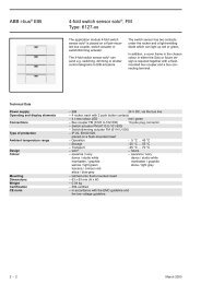
<strong>ABB</strong> i-bus ® <strong>EIB</strong><strong>Switch</strong>/<strong>dim</strong> <strong>actuator</strong>, <strong>FM</strong><strong>Type</strong>: <strong>6114</strong> U-<strong>500</strong> + 6323-xxUsing the parameters “Time base ...”and “Factor for <strong>dim</strong>ming range”, it ispossible to set the period which the<strong>dim</strong>ming <strong>actuator</strong> requires to <strong>dim</strong> up ordown fully once.IRIn addition to using the rockers, theBusch-triton ® switch sensor can alsobe controlled remotely via an infraredhand-held transmitter. The rockers andthe auxiliary push button can beassigned to the white or blue infraredarea of the hand-held transmitter. Therelevant setting must then be selectedvia the slide switch on the transmitter.The MEMO button of the transmittercorresponds to the function of theauxiliary push button of the Buschtriton® switch sensor.LCDThe display of the Busch-triton ® switchsensor can represent the values of fivedifferent communication objects.In order to display switching states,relative variables such as brightnessvalues, physical variables such astemperature values, the current time ordate, it is possible to parameteriseindividually the object value of eachLCD object from 1 bit to 3 bytes.The input of the display text andseveral further settings is carried outusing the Busch LCD managementsoftware. The software is available freeof charge on the <strong>EIB</strong> CD-ROM/diskette.The function of the software isdescribed in the Software/visualisationchapter. When entering the settings,you should ensure that the data(objects) of ETS2 and the displaymanagement software match.<strong>Switch</strong>In the default setting of the Buschtriton® switch sensor, there is a 1 bitcommunication object available forswitching for each of the rockers thatare not assigned lightscenes. Forspecial applications, the parameter“Number of switch functions” can beset so that each rocker has twocommunication objects.The parameter “Working mode of therocker” determines which value theswitch sensor sends when the left orthe right side of the rocker is pressed.DimIf the operation mode of the rocker isset to “Dimming sensor”, the rockerhas the communication objects“Rocker ... -short” for switching and“Rocker ... -long” for <strong>dim</strong>ming.When carrying out a switchingoperation, the rocker can either bepressed briefly on the left, on the rightor in the middle. The switch sensoralways toggles in this case.For <strong>dim</strong>ming, it is determined via theparameter “Dimming direction” whichside of the rocker must be pressed andheld down in order to <strong>dim</strong> up or down.When the rocker is released, theswitch sensor sends the telegram“Stop <strong>dim</strong>ming”.ShutterIf the operating mode of the rocker isset to “Shutter sensor”, the switchsensor sends “Move shutter up/down”telegrams when the left or right side ofthe rocker is pressed for a long period.After a short operation anywhere onthe rocker, it sends telegrams forstopping the shutter movement or forstepwise louvre adjustment.The parameter “Shutter direction”determines which side of the rockermust be pressed in order to moveupwards or downwards.LEDUsing the parameter “Operation modeof LED”, the LEDs can be selected foruse either as an orientation light or forstatus display.In the case of LEDs that are used forstatus display, it is possible to setwhich colour (red or green) isassigned to the object values “0” or “1”.The LEDs that are used as anorientation light can either always lightup red or always green or they can beswitched off.March 2003 8 - 115