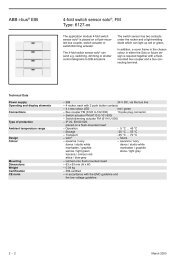
ABB i-bus® EIB Switch/dim actuator, FM Type: 6114 U-500
ABB i-bus® EIB Switch/dim actuator, FM Type: 6114 U-500
ABB i-bus® EIB Switch/dim actuator, FM Type: 6114 U-500

Create successful ePaper yourself
Turn your PDF publications into a flip-book with our unique Google optimized e-Paper software.
<strong>ABB</strong> i-bus ® <strong>EIB</strong><strong>Switch</strong>/<strong>dim</strong> <strong>actuator</strong>, <strong>FM</strong><strong>Type</strong>: <strong>6114</strong> U-<strong>500</strong> + 6325-xxApplication example:In a training room, there is a group of<strong>dim</strong>mable downlighters above theseminar participants, two <strong>dim</strong>mablespotlights above the lecture area andtwo groups with switchable wall lights.The room can be made darker usingtwo electrically driven shutters.When the seminar participants enterthe room, they should normally only beable to switch the wall lights as thebase lighting.Two 5-fold Busch-triton ® switchsensors with <strong>dim</strong>ming <strong>actuator</strong>/sensorsare used together with a <strong>dim</strong>ming<strong>actuator</strong>, a switch <strong>actuator</strong> and twoshutter <strong>actuator</strong>s.The two Busch-triton ® switch sensorsat the doors have almost the sameparameter settings:Function of auxiliary push button:Interrupt fault protectionOperation mode of rocker 1:<strong>Switch</strong>ing sensor,1 function, TOGGLEOperation mode of LED:shows value of object rockerColour of the LED:OFF = green, ON = redOperation mode of rocker 2:Dimming sensorOperation mode of LED:shows value of object rocker -shortColour of the LED:OFF = green, ON = redOperation mode of rocker 3:Dimming sensorOperation mode of LED:shows value of object rocker -shortColour of the LED:OFF = green, ON = redOperation mode of rocker 4:Shutter sensorOperation mode of LED:orientation lightColour of the LED:always offOperation mode of rocker 5:Shutter sensorOperation mode of LED:orientation lightColour of the LED:always offThe parameters “IR area” havedifferent settings so that both switchsensors do not send telegrams whenremote control is used.The outputs of the <strong>dim</strong>ming <strong>actuator</strong>s/sensors each control one of thespotlights above the lecture area.The link between the group addressesand the communication objects isalmost identical.The 1 bit communication objects no.1“Fault protection” are linked with the1 bit communication objects “Rocker 1”for both switch sensors and with theoutput of the switch <strong>actuator</strong> for thewall lights.The 1 bit and 4 bit communicationobjects of rocker 2 are linked with thecorresponding objects of the <strong>dim</strong>ming<strong>actuator</strong>s for the downlighters.The communication objects 7 to 9 ofthe <strong>dim</strong>ming <strong>actuator</strong>/sensors do notrequire group addresses in thisexample. To prepare for possibleextensions, it is however advisable toassign separate group addresses tothese objects of the two devices.The communication objects of rockers4 and 5 for raising and lowering theshutters and for louvre adjustment arelinked to the corresponding objects ofthe shutter <strong>actuator</strong>s.In principle, the switch sensors operatewith an active fault protection function.The wall lights are switched after eachoperation of any of the rockers.The lecturer can carry out the samefunctions via remote control. The IRarea can be set as required as bothswitch sensors react to differentsettings but carry out the samefunctions.8 - 140 March 2003