ABB i-bus® EIB Switch/dim actuator, FM Type: 6114 U-500
ABB i-bus® EIB Switch/dim actuator, FM Type: 6114 U-500
ABB i-bus® EIB Switch/dim actuator, FM Type: 6114 U-500

You also want an ePaper? Increase the reach of your titles
YUMPU automatically turns print PDFs into web optimized ePapers that Google loves.
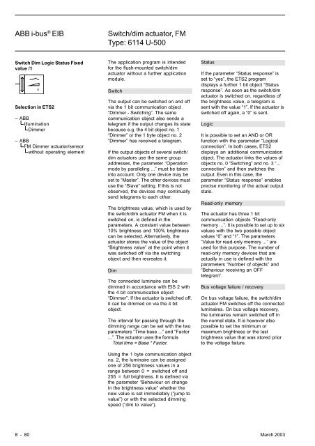
<strong>ABB</strong> i-bus ® <strong>EIB</strong><strong>Switch</strong>/<strong>dim</strong> <strong>actuator</strong>, <strong>FM</strong><strong>Type</strong>: <strong>6114</strong> U-<strong>500</strong><strong>Switch</strong> Dim Logic Status Fixedvalue /1Selection in ETS2– <strong>ABB</strong>IlluminationDimmer– <strong>ABB</strong><strong>FM</strong> Dimmer <strong>actuator</strong>/sensorwithout operating elementThe application program is intendedfor the flush-mounted switch/<strong>dim</strong><strong>actuator</strong> without a further applicationmodule.<strong>Switch</strong>The output can be switched on and offvia the 1 bit communication object“Dimmer - <strong>Switch</strong>ing”. The samecommunication object also sends atelegram if the output changes its statebecause e.g. the 4 bit object no. 1“Dimmer” or the 1 byte object no. 2“Dimmer” has received a telegram.If the output objects of several switch/<strong>dim</strong> <strong>actuator</strong>s use the same groupaddresses, the parameter “Operationmode by paralleling ...” must be takeninto account. Only one device may beset to “Master”. The other devices mustuse the “Slave” setting. If this is notobserved, the devices may continuallysend telegrams to each other.The brightness value, which is used bythe switch/<strong>dim</strong> <strong>actuator</strong> <strong>FM</strong> when it isswitched on, is defined in theparameters. A constant value between10% brightness and 100% brightnesscan be selected. Alternatively, the<strong>actuator</strong> stores the value of the object“Brightness value” at the point when itwas switched off via the switchingobject and then recreates it.DimThe connected luminaire can be<strong>dim</strong>med in accordance with EIS 2 withthe 4 bit communication object“Dimmer”. If the <strong>actuator</strong> is switched off,it can be <strong>dim</strong>med on via the 4 bitobject.The interval for passing through the<strong>dim</strong>ming range can be set with the twoparameters “Time base ...” and “Factor...”. The <strong>actuator</strong> uses the formulaTotal time = Base * Factor.Using the 1 byte communication objectno. 2, the luminaire can be assignedone of 256 brightness values in arange between 0 = switched off and255 = full brightness. It is defined viathe parameter “Behaviour on changein the brightness value” whether thenew value is set immediately (“jump tovalue”) or with the selected <strong>dim</strong>mingspeed (“<strong>dim</strong> to value”).StatusIf the parameter “Status response” isset to “yes”, the ETS2 programdisplays a further 1 bit object “Statusresponse”. As soon as the switch/<strong>dim</strong><strong>actuator</strong> is switched on, regardless ofthe brightness value, a telegram issent with the value “1”. If the <strong>actuator</strong> isswitched off again, a “0” is sent.LogicIt is possible to set an AND or ORfunction with the parameter “Logicalconnection”. In both cases, ETS2displays an additional communicationobject. The <strong>actuator</strong> links the values ofobjects no. 0 “<strong>Switch</strong>ing” and no. 3 “...connection” and then switches theoutput. Even in this case, theparameter “Status response” enablesprecise monitoring of the actual outputstate.Read-only memoryThe <strong>actuator</strong> has three 1 bitcommunication objects “Read-onlymemory ...”. It is possible to set up to sixvalues with the two possible objectvalues “0” and “1”. The parameters“Value for read-only memory ...” areused for this purpose. The number ofread-only memory devices that areactually in use is defined with theparameters “Number of objects” and“Behaviour receiving an OFFtelegram”.Bus voltage failure / recoveryOn bus voltage failure, the switch/<strong>dim</strong><strong>actuator</strong> <strong>FM</strong> switches off the connectedluminaires. On bus voltage recovery,the luminaires remain switched off inthe normal state. It is however alsopossible to set the minimum ormaximum brightness or the lastbrightness value that was stored priorto the voltage failure.8 - 80 March 2003