WAUKESHA Manuale Inglese AP2 - Asco Pompe Srl
WAUKESHA Manuale Inglese AP2 - Asco Pompe Srl
WAUKESHA Manuale Inglese AP2 - Asco Pompe Srl

Create successful ePaper yourself
Turn your PDF publications into a flip-book with our unique Google optimized e-Paper software.
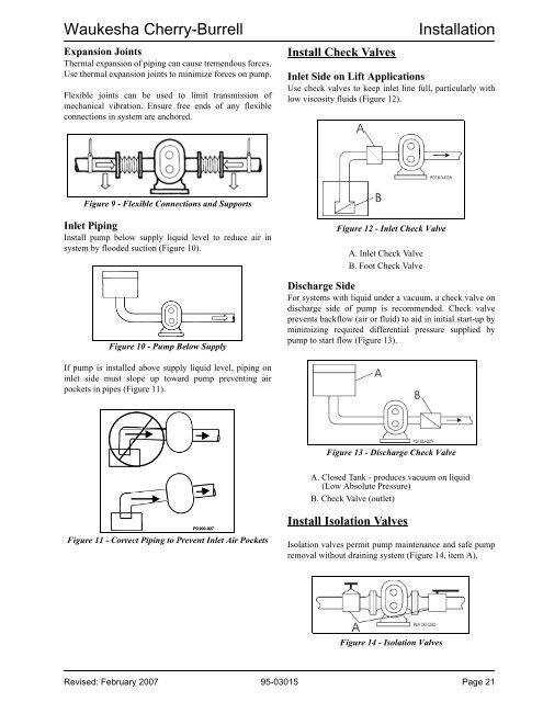
Waukesha Cherry-Burrell InstallationExpansion JointsThermal expansion of piping can cause tremendous forces.Use thermal expansion joints to minimize forces on pump.Flexible joints can be used to limit transmission ofmechanical vibration. Ensure free ends of any flexibleconnections in system are anchored.Install Check ValvesInlet Side on Lift ApplicationsUse check valves to keep inlet line full, particularly withlow viscosity fluids (Figure 12).Figure 9 - Flexible Connections and SupportsInlet PipingInstall pump below supply liquid level to reduce air insystem by flooded suction (Figure 10).Figure 10 - Pump Below SupplyFigure 12 - Inlet Check ValveA. Inlet Check ValveB. Foot Check ValveDischarge SideFor systems with liquid under a vacuum, a check valve ondischarge side of pump is recommended. Check valveprevents backflow (air or fluid) to aid in initial start-up byminimizing required differential pressure supplied bypump to start flow (Figure 13).If pump is installed above supply liquid level, piping oninlet side must slope up toward pump preventing airpockets in pipes (Figure 11).Figure 13 - Discharge Check ValveA. Closed Tank - produces vacuum on liquid(Low Absolute Pressure)B. Check Valve (outlet)Install Isolation ValvesFigure 11 - Correct Piping to Prevent Inlet Air PocketsIsolation valves permit pump maintenance and safe pumpremoval without draining system (Figure 14, item A).Figure 14 - Isolation ValvesRevised: February 2007 95-03015 Page 21