WAUKESHA Manuale Inglese AP2 - Asco Pompe Srl
WAUKESHA Manuale Inglese AP2 - Asco Pompe Srl
WAUKESHA Manuale Inglese AP2 - Asco Pompe Srl

Create successful ePaper yourself
Turn your PDF publications into a flip-book with our unique Google optimized e-Paper software.
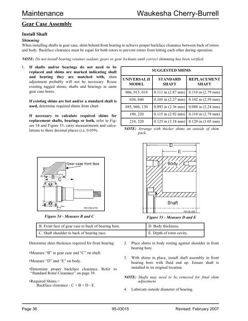
.MaintenanceGear Case AssemblyWaukesha Cherry-BurrellInstall ShaftShimmingWhen installing shafts in gear case, shim behind front bearing to achieve proper backface clearance between back of rotorsand body. Backface clearance must be equal for both rotors to prevent rotors from hitting each other during operation.NOTE: Do not install bearing retainer sealant, gears or gear locknuts until correct shimming has been verified.1. If shafts and/or bearings do not need to bereplaced and shims are marked indicating shaftand bearing they are matched with, shimadjustment probably will not be necessary. Reuseexisting tagged shims, shafts and bearings in samegear case bores.If existing shims are lost and/or a standard shaft isused, determine required shims from chart.If necessary to calculate required shims forreplacement shafts, bearings or both, refer to Figure54 and Figure 55; carry measurements and calculationsto three decimal places (i.e. 0.059).UNIVERSAL IIMODELSUGGESTED SHIMSSTANDARDSHAFTREPLACEMENTSHAFT006, 015, 018 0.113 in (2.87 mm) 0.110 in (2.79 mm)030, 040 0.105 in (2.27 mm) 0.102 in (2.59 mm)045, 060, 130 0.093 in (2.36 mm) 0.088 in (2.24 mm)180, 220 0.115 in (2.92 mm) 0.110 in (2.79 mm)210, 320 0.125 in (3.18 mm) 0.120 in (3.05 mm)NOTE: Arrange with thicker shims on outside of shimpack.Figure 54 - Measure B and CFigure 55 - Measure D and EB. Front face of gear case to back of bearing bore. D. Body thickness.C. Shaft shoulder to back of bearing race. E. Depth of rotor cavity.Determine shim thickness required for front bearing:•Measure “B” in gear case and “C” on shaft.•Measure “D” and “E” on body.•Determine proper backface clearance. Refer to“Standard Rotor Clearance” on page 39.•Required Shims =Backface clearance - C + B + D - E.2. Place shims in body resting against shoulder in frontbearing bore.3. With shims in place, install shaft assembly in frontbearing bore with fluid end up. Ensure shaft isinstalled in its original location.NOTE: Shafts may need to be removed for final shimadjustment.4. Lubricate outside diameter of bearing.Page 36 95-03015 Revised: February 2007