WAUKESHA Manuale Inglese AP2 - Asco Pompe Srl
WAUKESHA Manuale Inglese AP2 - Asco Pompe Srl
WAUKESHA Manuale Inglese AP2 - Asco Pompe Srl

Create successful ePaper yourself
Turn your PDF publications into a flip-book with our unique Google optimized e-Paper software.
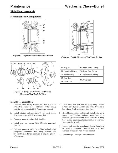
MaintenanceFluid Head AssemblyWaukesha Cherry-BurrellMechanical Seal ConfigurationFigure 67 - Single Mechanical Seal Cross SectionFigure 68 - Double Mechanical Seal Cross Section37. Stop Pin 95. Inner Wave Spring91. Inner Seal O-ring 96. Outer Seal O-ring92. Shaft O-ring 97. Outer Wave Spring93. Seal Seat98. Outer Seal94. Inner SealFigure 69 - Single (Bottom) and Double (Top)Mechanical Seal Exploded ViewInstall Mechanical Seal1. Lubricate shaft o-ring (Figure 69, item 92) withlubrication compound compatible with o-ringmaterial and process fluid(s). Place o-ring on shaft.2. Install rotating seal seat (item 93) on shaft. Aligndrive flats on seat with drive flats on shaft.3. Push seat squarely against shaft shoulder.4. Install inner wave spring (item 95) onto inner seal(item 94).5. Lubricate inner seal o-ring (item 91) with lubricationcompound compatible with o-ring material andprocess fluid(s). Install inner seal o-ring into grooveof inner seal.6. Place inner seal into back of pump body. Ensurenotches are aligned in inner seal with stop pins inbody. Press firmly and evenly into place.7. If double mechanical seal is used, install outer wavespring (item 97) in body and outer o-ring (item 96) inouter seal groove (item 98). Place outer seal in pumpbody around inner seal, aligning notches in outer sealwith stop pins in body.8. Inspect seal faces for cleanliness. Ensure faces haveno nicks or scratches. Lubricate seal faces withlubricant compatible with process fluid(s).9. Perform steps 1 through 5 on both shafts.Page 40 95-03015 Revised: February 2007