WAUKESHA Manuale Inglese AP2 - Asco Pompe Srl
WAUKESHA Manuale Inglese AP2 - Asco Pompe Srl
WAUKESHA Manuale Inglese AP2 - Asco Pompe Srl

Create successful ePaper yourself
Turn your PDF publications into a flip-book with our unique Google optimized e-Paper software.
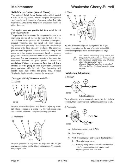
MaintenanceRelief Cover Option (Vented Cover)The optional Relief Cover Feature (also called VentedCover) is an adjustable, internal by-pass arrangementwhich can be used for control of pressure and/or flow. It isbidirectional; that is the pump flow or rotation can be ineither direction.This option does not provide full flow relief for allpumping situations.The pressure down stream of the pump may increase withincreasing amount of by-pass through the Relief Cover.Actual down stream pressure will depend on pump speed,product viscosity, and the relief set point (springadjustment or air pressure). Avoid high flow rates throughthe cover with high viscosity products. The resultingpressure may be greater than the maximum rating of thepump or other system components. Install a pressuregauge and measure pressure under worst conditions ofmaximum flow and maximum viscosity to determine themaximum pressure for your process. Under anyconditions, if there is a complete flow shut off downstream, stop the pump as soon as possible. Continuedpump operation with the entire flow by-passing willrapidly build heat within the pump body. ContactWaukesha Application Engineering for assistance.Three types of Relief Covers are available:1. Manual3. PistonWaukesha Cherry-Burrell16 15 14 13 1By-pass pressure is adjusted by regulated air or gaspressure, operating on the side of a metal piston (12),opposite the pumped fluid. Extended pressure rangepossible.NOTE: On all types of relief covers, thetemperature and chemical resistance ofthe elastomer diaphragms and O-ringsdetermine the useful range.Buna-N: Material supplied as standardSilicone Rubber: Optional material uponrequestInstallation Adjustment1. Manual12 172 4 7 5 3 6 81By-pass pressure is adjusted by a threaded adjusting screw(2) which compresses a spring (5). Several spring sizesare available, to cover a range of operating pressures.Turn adjusting screw counterclockwise to its farthestposition, then clockwise until light spring pressure is felt.2. PneumaticAdjusting Screw2. Pneumatic11 10 9 1A. Set air/gas pressure to 2-5 PSIGB. Turn on pump.By-pass pressure is adjusted by regulated air or gaspressure, operating on the side of a diaphragm (9) oppositethe pumped fluid.C. With pressure gauge and valve in discharge line:1. Close discharge valve.2. Turn adjusting screw clockwise until desiredrelief pressure registers on gauge. Lockadjusting screw with lock nut.Page 44 95-03015 Revised: February 2007