WAUKESHA Manuale Inglese AP2 - Asco Pompe Srl
WAUKESHA Manuale Inglese AP2 - Asco Pompe Srl
WAUKESHA Manuale Inglese AP2 - Asco Pompe Srl
You also want an ePaper? Increase the reach of your titles
YUMPU automatically turns print PDFs into web optimized ePapers that Google loves.
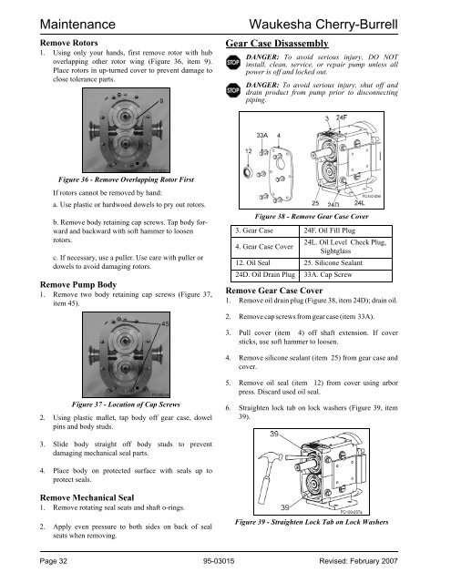
MaintenanceRemove Rotors1. Using only your hands, first remove rotor with huboverlapping other rotor wing (Figure 36, item 9).Place rotors in up-turned cover to prevent damage toclose tolerance parts.Waukesha Cherry-BurrellGear Case DisassemblyDANGER: To avoid serious injury, DO NOTinstall, clean, service, or repair pump unless allpower is off and locked out.DANGER: To avoid serious injury, shut off anddrain product from pump prior to disconnectingpiping.Figure 36 - Remove Overlapping Rotor FirstIf rotors cannot be removed by hand:a. Use plastic or hardwood dowels to pry out rotors.b. Remove body retaining cap screws. Tap body forwardand backward with soft hammer to loosenrotors.c. If necessary, use a puller. Use care with puller ordowels to avoid damaging rotors.Remove Pump Body1. Remove two body retaining cap screws (Figure 37,item 45).Figure 38 - Remove Gear Case Cover3. Gear Case 24F. Oil Fill Plug4. Gear Case Cover24L. Oil Level Check Plug,Sightglass12. Oil Seal 25. Silicone Sealant24D. Oil Drain Plug 33A. Cap ScrewRemove Gear Case Cover1. Remove oil drain plug (Figure 38, item 24D); drain oil.2. Remove cap screws from gear case (item 33A).3. Pull cover (item 4) off shaft extension. If coversticks, use soft hammer to loosen.4. Remove silicone sealant (item 25) from gear case andcover.Figure 37 - Location of Cap Screws2. Using plastic mallet, tap body off gear case, dowelpins and body studs.5. Remove oil seal (item 12) from cover using arborpress. Discard used oil seal.6. Straighten lock tab on lock washers (Figure 39, item39).3. Slide body straight off body studs to preventdamaging mechanical seal parts.4. Place body on protected surface with seals up toprotect seals.Remove Mechanical Seal1. Remove rotating seal seats and shaft o-rings.2. Apply even pressure to both sides on back of sealseats when removing.Figure 39 - Straighten Lock Tab on Lock WashersPage 32 95-03015 Revised: February 2007


