E2 User Manual.book - Emerson Climate Technologies
E2 User Manual.book - Emerson Climate Technologies
E2 User Manual.book - Emerson Climate Technologies

You also want an ePaper? Increase the reach of your titles
YUMPU automatically turns print PDFs into web optimized ePapers that Google loves.
The PAK can control up to 4 condenser fan groups<br />
containing up to 8 total condenser fans. The PAK condenser<br />
control strategy is sequential TD control with setpoint/deadband<br />
using ON and OFF delays.<br />
The PAK has a compressor/condenser interlock feature<br />
that will override TD control and force the condenser<br />
fans to stage off using the TD control OFF delay when all<br />
compressors are off. This feature can be disabled with an<br />
Enable/Disable setpoint or when the discharge pressure is<br />
above a configurable setpoint.<br />
The MultiFlex PAK boards consist of two circuit<br />
boards: a bottom layer with 16 combination digital/analog<br />
inputs, and a plug-in top layer which contains a combination<br />
of 8 relay outputs and 4 digital DC voltage outputs.<br />
The analog outputs on the Multiflex PAK drive solid<br />
state relays to control the fan stages. The relays control the<br />
compressor groups.<br />
The communication interface is RS485 I/O using the<br />
Standard Extended Address Form for Retail Solutions Distributed<br />
Controllers. Currently, the PAK is designed to<br />
interface with the Retail Solutions <strong>E2</strong> controller.<br />
1 INPUT POWER<br />
(24VAC)<br />
LEGEND<br />
9 RS485 TERMINATION<br />
JUMPERS<br />
2 RS485 I/O NETWORK 10 HAND-HELD<br />
TERMINAL JACK<br />
3 PAK INPUTS 1-8 11 RELAY OUTPUT<br />
CONNECTORS<br />
4 PAK INPUTS 9-16 12 RELAY OUTPUT FUSES<br />
(2A rated, 250V slowblow)<br />
5 NETWORK ID DIP<br />
SWITCH (S3)<br />
13 RELAY STATUS LEDs<br />
6 INPUT TYPE DIP<br />
SWITCHES (S1, S2)<br />
7 BOARD STATUS LEDs<br />
(Code A, Code B, General<br />
Status)<br />
8 DC POWER OUTPUTS<br />
(3 at +5VDC, 1 at<br />
+12VDC)<br />
Table 2-9 - MultiFlex PAK<br />
14 RELAY FAIL-SAFE<br />
SWITCHES<br />
15 PAK ANALOG<br />
OUTPUTS 1-4<br />
16 NETWORK STATUS<br />
LEDs<br />
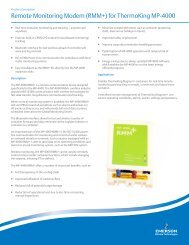
2.2.3 The MultiFlex ESR Board<br />
The MultiFlex ESR Valve Regulator board (P/N 810-<br />
3199), shown in Figure 2-1, is an RS485 I/O Network<br />
electronic stepper valve regulator capable of driving up to<br />
eight stepper motor valves, which are typically used to<br />
control temperature.<br />
Figure 2-1 - MultiFlex ESR Board Layout<br />
The MultiFlex ESR uses suction side variable-position<br />
evaporator regulators (ESRs) to vary evaporator pressure<br />
for an entire circuit and is an alternative to mechanical<br />
EPR control.<br />
The MultiFlex ESR receives input data from a Retail<br />
Solutions <strong>E2</strong> controller (via the I/O Network) and then<br />
regulates the stepper valves according to the data from the<br />
<strong>E2</strong>.<br />
Each MultiFlex ESR board requires a Class 2, 80VA<br />
24VAC center-tapped transformer for power. Retail Solutions<br />
transformer (P/N 640-0080) is a multi-tapped primary<br />
transformer that may be used with the MultiFlex<br />
ESR board.<br />
2.2.4 Hand-held Terminal (P/N<br />
814-3110)<br />
The Hand-held Terminal (HHT) is used by manufacturers<br />
and service technicians to diagnose and test several<br />
of Retail Solutions' existing and legacy products. The<br />
HHT can be used on any Retail Solutions product with an<br />
RJ-11 connector. The most common applications include:<br />
• All MultiFlex I/O boards and the 8ROSMT<br />
• All Gateway boards<br />
• Stand-alone MultiFlex boards (RTU, RCB, PAK,<br />
CUB)<br />
2-8 • <strong>E2</strong> RX/BX/CX I&O <strong>Manual</strong> 026-1610 Rev 10 06-APR-2010<br />
3<br />
7<br />
3<br />
8<br />
10<br />
1 Valve Connectors (8) 6 Termination Jumpers<br />
2 24VAC CT 75 VAC Power Input 7 HHT Jack<br />
General Status LED 8 Network Address Switches<br />
4 I/O Network Input<br />
9 Open LED (8)<br />
5 TX and RX LEDs<br />
10 Close LED (8)<br />
9