E2 User Manual.book - Emerson Climate Technologies
E2 User Manual.book - Emerson Climate Technologies
E2 User Manual.book - Emerson Climate Technologies

Create successful ePaper yourself
Turn your PDF publications into a flip-book with our unique Google optimized e-Paper software.
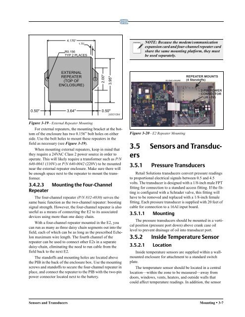
Figure 3-19 - External Repeater Mounting<br />
For external repeaters, the mounting bracket at the bottom<br />
of the enclosure has two 0.156” bolt holes on either<br />
side. Use the bolt holes to mount these repeaters in the<br />
field as necessary (see Figure 3-19).<br />
When mounting external repeaters, keep in mind that<br />
they require a 24VAC Class 2 power source in order to<br />
operate. This will likely require a transformer such as P/N<br />
640-0041 (110V) or P/N 640-0042 (220V) to be mounted<br />
near the external repeater enclosure. Make sure there will<br />
be enough space next to the repeater to mount the transformer.<br />
3.4.2.3 Mounting the Four-Channel<br />
Repeater<br />
The four-channel repeater (P/N 832-4830) serves the<br />
same basic function as the two-channel repeater: boosting<br />
signal strength. However, the four-channel repeater is also<br />
useful as a means of connecting the <strong>E2</strong> to its associated<br />
devices using more than one daisy chain.<br />
With a four-channel repeater mounted in the <strong>E2</strong>, you<br />
can run as many as three daisy chain segments out into the<br />
field, each of which can be as long as the prescribed Echelon<br />
maximum wire length. The fourth channel of the<br />
repeater can be used to connect other <strong>E2</strong>s in a separate<br />
daisy-chain, eliminating the need to run cable from the<br />
field back to the next <strong>E2</strong>.<br />
The standoffs and mounting holes are located above<br />
the PIB in the back of the enclosure box. Use the mounting<br />
screws and standoffs to secure the four-channel repeater in<br />
place, and connect the repeater to the PIB with the two-pin<br />
power connector located next to the battery.<br />
NOTE: Because the modem/communication<br />
expansion card and four-channel repeater card<br />
share the same mounting platform, they must<br />
be used separately.<br />
<strong>E2</strong> ENCLOSURE<br />
Figure 3-20 - <strong>E2</strong> Repeater Mounting<br />
REPEATER MOUNTS<br />
(4 Standoffs)<br />
3.5 Sensors and Transducers<br />
3.5.1 Pressure Transducers<br />
PIB<br />
2-PIN POWER<br />
CONNECTOR<br />
(J8 +5V)<br />
Retail Solutions transducers convert pressure readings<br />
to proportional electrical signals between 0.5 and 4.5<br />
volts. The transducer is designed with a 1/8-inch male FPT<br />
fitting for connection to a standard access fitting. If the fitting<br />
is configured with a Schrader valve, this fitting will<br />
have to be removed and replaced with a 1/8-inch female<br />
fitting. Each pressure transducer is supplied with 20 feet of<br />
cable for connection to a 16AI input board.<br />
3.5.1.1 Mounting<br />
The pressure transducers should be mounted in a vertical<br />
position (pressure port down) above crank case oil<br />
level to prevent drainage of oil into transducer port.<br />
3.5.2 Inside Temperature Sensor<br />
3.5.2.1 Location<br />
Inside temperature sensors are supplied within a wallmounted<br />
enclosure for attachment to a standard switch<br />
plate.<br />
The temperature sensor should be located in a central<br />
location—within the zone to be measured—away from<br />
doors, windows, vents, heaters, and outside walls that<br />
could affect temperature readings. In addition, the sensor<br />
Sensors and Transducers Mounting • 3-7