E2 User Manual.book - Emerson Climate Technologies
E2 User Manual.book - Emerson Climate Technologies
E2 User Manual.book - Emerson Climate Technologies

Create successful ePaper yourself
Turn your PDF publications into a flip-book with our unique Google optimized e-Paper software.
Modem P/N Description<br />
637-4871<br />
COM3<br />
Plug-In<br />
Modem<br />
637-4872<br />
637-4873<br />
COM6<br />
RS232<br />
COM6<br />
RS485<br />
COM6<br />
RS232<br />
COM6<br />
RS485<br />
COM3 RS232<br />
Plug-In for<br />
External Modem<br />
COM6<br />
RS232<br />
COM6<br />
RS485<br />
Modem/com expansion card with modem and RS485<br />
serial communication port plug-in.<br />
Note that the RS232 and RS485 ports are counted as one<br />
port (COM6); only one connector at a time may be used.<br />
The COM6 RS232 will be selectable in future versions<br />
of <strong>E2</strong>.<br />
Modem/com expansion card with an RS232 plug-in<br />
(COM3) that can interface with an external modem, and<br />
an RS485 serial communication port plug-in. This model<br />
comes with a cable that has a male DB-9 header and a<br />
DB-9 to DB-25 converter (not shown) to support the<br />
standard external modem interface.<br />
Note that the RS232 and RS485 ports are counted as one<br />
port (COM6); only one connector at a time may be used.<br />
The COM6 RS232 will be selectable in future versions<br />
of <strong>E2</strong>.<br />
Com expansion card with RS485 serial communication<br />
port.<br />
Note that the RS232 and RS485 ports are counted as one<br />
port (COM6); only one connector at a time may be used.<br />
The COM6 RS232 will be selectable in future versions<br />
of <strong>E2</strong>.<br />
Table 4-1 - Modem/Com Card Part Numbers and Descriptions<br />
4.3.3 Plug-In Modem Card (P/N<br />
537-4870) with mounting screws<br />
(P/N 101-4038) and standoffs (P/N<br />
107-9440) (Previous Generation Processor<br />
Board)<br />
The <strong>E2</strong>’s internal modem mounts in the PC-104 slot<br />
located at the top left edge of the <strong>E2</strong> main processor board<br />
(See Figure 3-18 on page 3-6). Disconnect power to the<br />
unit, and carefully plug the male pins on the back of the<br />
modem card into the <strong>E2</strong>’s PC-104 slot. Use the standoffs<br />
and screws supplied with the modem card to secure the<br />
card to the main processor board, as shown in Figure 3-18<br />
on page 3-6). When finished, restore power to the <strong>E2</strong>.<br />
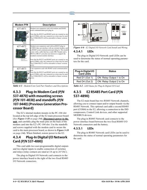
4.3.4 Plug-In Digital I/O Network<br />
Card (P/N 537-4880)<br />
This card adds two user-programmable digital outputs<br />
and two digital inputs to enable connection of switches<br />
and relays (relay contacts are rated at 3A up to 24 VAC).<br />
The plug-in Digital I/O Network card connects to the<br />
power interface board to the right of the two fixed RS485<br />
I/O Network connectors.<br />
<strong>E2</strong> Plug-In<br />
Digital I/O<br />
Network Card<br />
Figure 4-6 - <strong>E2</strong> Digital I/O Network Card Install and Wiring<br />
4.3.4.1 LEDs<br />
The plug-in Digital I/O Network card LEDs can be<br />
used to determine the status of normal operating parameters<br />
for the card.<br />
Plug-In Digital I/O<br />
Status<br />
Card LEDs<br />
Red D1 (Out 1) ON: Relay Output 1 is On<br />
Red D4 (Out 2) ON: Relay Output 2 is On<br />
Table 4-2 - LED Status for Plug-In Digital I/O Card<br />
4.3.5 <strong>E2</strong> RS485 Port Card (P/N<br />
537-4890)<br />
The <strong>E2</strong> main board has two RS485 Network channels,<br />
allowing you to connect input and/or output boards via the<br />
RS485 Network. This optional card adds a second RS485<br />
port (COM4) to the <strong>E2</strong>, allowing a connection to the ISD<br />
compressors, Control Link devices, and other supported<br />
MODBUS devices.<br />
The plug-in RS485 Network card connects to the<br />
power interface board between the two fixed RS485 I/O<br />
Network connectors and the battery.<br />
4.3.5.1 LEDs<br />
<strong>E2</strong> Power Interface Board (PIB)<br />
Input and Output Wiring<br />
NORMALLY<br />
OPEN<br />
The plug-in RS485 Network card LEDs can be used to<br />
determine the status of normal operating parameters for<br />
the card.<br />
4-4 • <strong>E2</strong> RX/BX/CX I&O <strong>Manual</strong> 026-1610 Rev 10 06-APR-2010<br />
COM 1 COM 2<br />
OUTPUT #1<br />
OUTPUT #2<br />
INPUT #1<br />
INPUT #2<br />
NORMALLY<br />
CLOSED