E2 User Manual.book - Emerson Climate Technologies
E2 User Manual.book - Emerson Climate Technologies
E2 User Manual.book - Emerson Climate Technologies

Create successful ePaper yourself
Turn your PDF publications into a flip-book with our unique Google optimized e-Paper software.
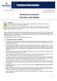
3.3.2 CC-100 Case Controller and<br />
CS-100 Case Circuit Controller<br />
Generally, the case controller will be mounted within<br />
the raceway or on top of the case. If a controller must be<br />
replaced or installed in the field, it should be located based<br />
on the specific design of the case.<br />
3.00"<br />
2.00"<br />
2.25"<br />
0.50"<br />
0.50"<br />
8.95"<br />
8.05"<br />
CONTROLLER<br />
(TOP VIEW)<br />
CONTROLLER<br />
(SIDE VIEW)<br />
Figure 3-13 - CCB Mounting Dimensions<br />
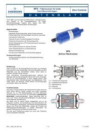
3.3.3 ESR8 (Discontinued)<br />
The ESR8 board is slightly larger than the 16AI and<br />
8RO boards, and is not supplied with a snap-track. If the<br />
ESR8 is supplied without an enclosure, it is supplied with<br />
0.500” long metal stand-off dowels which are pressed into<br />
the mounting holes in the board (See Figure 3-14).<br />
Figure 3-14 - Mounting Dimensions for the ESR8<br />
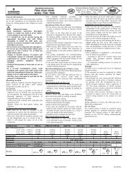
3.3.4 MultiFlex ESR<br />
0.25"<br />
O 0.18“<br />
TYP 2 PLACES<br />
26502032<br />
The MultiFlex ESR is supplied with a snap-track. If<br />
the ESR8 is supplied without an enclosure, it is supplied<br />
with 0.500” long metal stand-off dowels that are pressed<br />
into the mounting holes in the board.<br />
0.25"<br />
O 0.25"<br />
TYP 2 PLACES<br />
Figure 3-15 - Mounting Dimensions for the MultiFlex ESR<br />
3.3.5 TD3<br />
The TD3 temperature display is almost always<br />
mounted by the OEM as part of the construction of the<br />
refrigerated cases. As such, field installations of TD3s are<br />
rare.<br />
TD3s are typically flush mounted on the front of a<br />
refrigerated case in such a way as to be fully visible from<br />
the sales floor. A hole one inch in diameter must be drilled<br />
into the case to allow the TD3’s wiring harness to extend<br />
into the case and connect to the network, the power source,<br />
and the case-mounted probes. Figure 3-16 shows the<br />
mounting dimensions of the TD3.<br />
Figure 3-16 - TD3 Mounting Dimensions<br />
3.4 Modem/Communication<br />
Expansion Card Mounting<br />
(New Processor Board)<br />
The <strong>E2</strong>’s modem/communication expansion card<br />
mounts above the PIB in the back of the enclosure box as<br />
shown in Figure 3-17. The standoffs and mounting holes<br />
are located above the PIB in the back of the enclosure box.<br />
Use the mounting screws and standoffs to secure the card<br />
in place. The ribbon cable plugs into the "Modem/Com 6"<br />
slot on the motherboard. For more information on the<br />
modem/communication expansion card, see Section 4.3.2,<br />
Modem/Communication Expansion Card (New Proces-<br />
Modem/Communication Expansion Card Mounting (New Processor Board) Mounting • 3-5<br />
4.00"<br />
3.50"<br />
4.75"<br />
TYP 2 PL<br />
10.00"<br />
MULTIFLEX ESR BOARD<br />
WEIGHT 9.4 OZ.<br />
9.50"<br />
O 0.220"<br />
TYP 6 PL<br />
26501055