E2 User Manual.book - Emerson Climate Technologies
E2 User Manual.book - Emerson Climate Technologies
E2 User Manual.book - Emerson Climate Technologies

Create successful ePaper yourself
Turn your PDF publications into a flip-book with our unique Google optimized e-Paper software.
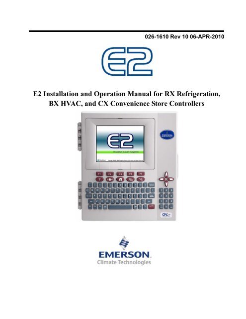
026-1610 Rev 10 06-APR-2010<br />
<strong>E2</strong> Installation and Operation <strong>Manual</strong> for RX Refrigeration,<br />
BX HVAC, and CX Convenience Store Controllers
3240 Town Point Drive NW, Suite 100<br />
Kennesaw, GA 30144, USA<br />
Phone 770-425-2724<br />
Fax 770-425-9319<br />
ALL RIGHTS RESERVED<br />
The information contained in this manual has been carefully checked and is believed<br />
to be accurate. However, Computer Process Controls, Inc. assumes no responsibility<br />
for any inaccuracies that may be contained herein. In no event will Computer Process<br />
Controls, Inc. be liable for any direct, indirect, special, incidental, or consequential<br />
damages resulting from any defect or omission in this manual, even if advised of the<br />
possibility of such damages. In the interest of continued product development, Computer<br />
Process Controls, Inc. reserves the right to make improvements to this manual,<br />
and the products described herein, at any time without notice or obligation.<br />
FCC COMPLIANCE NOTICE<br />
This device complies with Part 15 of the FCC Rules. Operation is subject to the following<br />
two conditions: (1) this device may not cause harmful interference, and (2) this<br />
device must accept any interference received, including interference that may cause<br />
undesired operation.<br />
CE COMPLIANCE NOTICE<br />
Class A Product Information for Einstein, <strong>E2</strong> Controllers:<br />
The Retail Solutions Einstein and <strong>E2</strong> controllers are Class A products. In a domestic<br />
environment this product may cause radio interference in which case the user may be<br />
required to take adequate measures. This covers:<br />
• All Einstein family product types: RX - Refrigeration Controller<br />
(830-xxxx), BX - Building/HVAC Controller (831-xxxx), and all version<br />
models: (300, 400, 500).<br />
• All <strong>E2</strong> family product types: RX - Refrigeration Controller (834-xxxx),<br />
BX - Building/HVAC Controller (835-xxxx), CX- Convenience Store<br />
Controller (836-xxxx), and all version models: (300, 400, 500).
Table of Contents<br />
1 INTRODUCTION...................................................................................................................................................... 1-1<br />
1.1 THE <strong>E2</strong> REFRIGERATION CONTROLLER..................................................................................................................... 1-1<br />
1.2 THE <strong>E2</strong> BUILDING CONTROLLER............................................................................................................................... 1-1<br />
1.3 THE <strong>E2</strong> CONVENIENCE STORE CONTROLLER............................................................................................................ 1-2<br />
1.4 NETWORKING OVERVIEW.......................................................................................................................................... 1-3<br />
1.4.1 <strong>E2</strong> I/O Network .................................................................................................................................................. 1-3<br />
1.4.2 The <strong>E2</strong> Echelon Lonworks Network................................................................................................................... 1-3<br />
1.4.3 Interconnection With Other <strong>E2</strong>s ........................................................................................................................ 1-4<br />
1.5 DOCUMENTATION OVERVIEW ................................................................................................................................... 1-5<br />
1.6 ON-LINE HELP SYSTEM OVERVIEW .......................................................................................................................... 1-6<br />
1.7 SOFTWARE LICENSING............................................................................................................................................... 1-6<br />
2 HARDWARE OVERVIEW...................................................................................................................................... 2-1<br />
2.1 <strong>E2</strong> HARDWARE .......................................................................................................................................................... 2-1<br />
2.1.1 <strong>E2</strong> Main Processor Board (CPU)...................................................................................................................... 2-2<br />
2.1.2 <strong>E2</strong> Processor Interface Board (PIB).................................................................................................................. 2-2<br />
2.1.3 <strong>E2</strong> Keypad.......................................................................................................................................................... 2-2<br />
2.1.4 LEDs................................................................................................................................................................... 2-2<br />
2.1.5 PC-104 Peripherals: The Internal Modem (Previous Generation Processor Board)....................................... 2-3<br />
2.2 I/O NETWORK BOARDS AND PERIPHERALS............................................................................................................... 2-3<br />
2.2.1 The Gateway Board ........................................................................................................................................... 2-3<br />
2.2.2 MultiFlex Boards ............................................................................................................................................... 2-4<br />
2.2.2.1 MultiFlex 16 Input Board ........................................................................................................................................ 2-4<br />
2.2.2.2 MultiFlex Combination Input/Output Boards.......................................................................................................... 2-5<br />
2.2.2.3 MultiFlex CUB ........................................................................................................................................................ 2-7<br />
2.2.2.4 MultiFlex RTU (BX and CX Only)......................................................................................................................... 2-7<br />
2.2.2.5 MultiFlex Rooftop Control Board (RCB) (BX and CX Only) ................................................................................ 2-7<br />
2.2.2.6 MultiFlex PAK Board.............................................................................................................................................. 2-7<br />
2.2.3 The MultiFlex ESR Board.................................................................................................................................. 2-8<br />
2.2.4 Hand-held Terminal (P/N 814-3110)................................................................................................................. 2-8<br />
2.2.5 The 8RO and 8ROSMT Relay Boards................................................................................................................ 2-9<br />
2.2.6 4AO Analog Output Board............................................................................................................................... 2-10<br />
2.2.7 8DO Digital Output Board and PMAC II Anti-Sweat Controller ................................................................... 2-10<br />
2.3 ECHELON NETWORK BOARDS AND PERIPHERALS................................................................................................... 2-11<br />
2.3.1 The 16AIe (Discontinued) ................................................................................................................................ 2-11<br />
2.3.2 The 8ROe (Discontinued)................................................................................................................................. 2-11<br />
2.3.3 EC-2s................................................................................................................................................................ 2-11<br />
2.3.4 CC-100 Case Controllers and CS-100 Case Circuit Controllers.................................................................... 2-12<br />
2.3.5 The ESR8 (Discontinued)................................................................................................................................. 2-12<br />
2.3.6 TD3 Temperature Display ............................................................................................................................... 2-13<br />
2.3.7 Facility Status Display (FSD).......................................................................................................................... 2-13<br />
3 MOUNTING............................................................................................................................................................... 3-1<br />
3.1 MOUNTING THE <strong>E2</strong>.................................................................................................................................................... 3-1<br />
3.1.1 Standard Mount.................................................................................................................................................. 3-1<br />
3.1.2 Recessed Mount.................................................................................................................................................. 3-1<br />
3.1.3 Retrofit Mounting............................................................................................................................................... 3-2<br />
3.1.4 Blank Face ......................................................................................................................................................... 3-3<br />
3.2 MOUNTING I/O BOARDS............................................................................................................................................ 3-3<br />
<strong>E2</strong> RX/BX/CX I&O <strong>Manual</strong> Table of Contents • v
3.2.1 Single/Double Enclosures ................................................................................................................................. 3-3<br />
3.2.2 Boards Without Enclosures (Snap Track).......................................................................................................... 3-4<br />
3.3 ECHELON DEVICES .................................................................................................................................................... 3-4<br />
3.3.1 16AIe and 8ROe ................................................................................................................................................. 3-4<br />
3.3.2 CC-100 Case Controller and CS-100 Case Circuit Controller ......................................................................... 3-5<br />
3.3.3 ESR8 (Discontinued).......................................................................................................................................... 3-5<br />
3.3.4 MultiFlex ESR .................................................................................................................................................... 3-5<br />
3.3.5 TD3..................................................................................................................................................................... 3-5<br />
3.4 MODEM/COMMUNICATION EXPANSION CARD MOUNTING (NEW PROCESSOR BOARD) ........................................... 3-5<br />
3.4.1 Mounting PC-104 Cards in <strong>E2</strong> (Previous Generation Processor Board) ......................................................... 3-6<br />
3.4.1.1 The Internal Modem ................................................................................................................................................ 3-6<br />
3.4.2 Two-Channel and Four-Channel Repeaters ...................................................................................................... 3-6<br />
3.4.2.1 Mounting Repeaters Overview ................................................................................................................................ 3-6<br />
3.4.2.2 Mounting the Two-Channel Repeater...................................................................................................................... 3-6<br />
3.4.2.3 Mounting the Four-Channel Repeater ..................................................................................................................... 3-7<br />
3.5 SENSORS AND TRANSDUCERS.................................................................................................................................... 3-7<br />
3.5.1 Pressure Transducers......................................................................................................................................... 3-7<br />
3.5.1.1 Mounting.................................................................................................................................................................. 3-7<br />
3.5.2 Inside Temperature Sensor................................................................................................................................. 3-7<br />
3.5.2.1 Location ................................................................................................................................................................... 3-7<br />
3.5.2.2 Mounting.................................................................................................................................................................. 3-8<br />
3.5.3 Outside Temperature Sensor.............................................................................................................................. 3-8<br />
3.5.3.1 Location ................................................................................................................................................................... 3-8<br />
3.5.3.2 Mounting.................................................................................................................................................................. 3-8<br />
3.5.4 Insertion Temperature Probe............................................................................................................................. 3-8<br />
3.5.4.1 Location ................................................................................................................................................................... 3-8<br />
3.5.4.2 Mounting.................................................................................................................................................................. 3-8<br />
3.5.5 Supply and Return Air Sensors........................................................................................................................... 3-8<br />
3.5.6 Refrigeration System Temperature Probes and Sensors.................................................................................... 3-9<br />
3.5.6.1 Location ................................................................................................................................................................... 3-9<br />
3.5.6.2 Mounting Bullet and Pipe Mount Sensors............................................................................................................... 3-9<br />
3.5.7 Product Temperature Probes............................................................................................................................. 3-9<br />
3.5.8 Humidity Sensors and Humidistats .................................................................................................................... 3-9<br />
3.5.8.1 Indoor RH Sensor .................................................................................................................................................... 3-9<br />
3.5.8.2 Outdoor RH Sensors .............................................................................................................................................. 3-10<br />
3.5.8.3 Duct-mounted Insertion RH Probe ........................................................................................................................ 3-10<br />
3.5.9 Dewpoint Probe................................................................................................................................................ 3-11<br />
3.5.9.1 Location ................................................................................................................................................................. 3-11<br />
3.5.9.2 Mounting................................................................................................................................................................ 3-11<br />
3.5.10 Light Level Sensor.......................................................................................................................................... 3-11<br />
3.5.10.1 Location ............................................................................................................................................................... 3-11<br />
3.5.10.2 Mounting.............................................................................................................................................................. 3-11<br />
3.5.11 Liquid Level Sensors ...................................................................................................................................... 3-11<br />
3.5.12 Refrigerant Leak Detectors ............................................................................................................................ 3-11<br />
4 <strong>E2</strong> HARDWARE SETUP .......................................................................................................................................... 4-1<br />
4.1 SETTING UP THE <strong>E2</strong> ................................................................................................................................................... 4-1<br />
4.1.1 Enclosure............................................................................................................................................................ 4-1<br />
4.1.2 Main Processor Board ....................................................................................................................................... 4-1<br />
4.1.3 Main Processor Board (Previous Version)........................................................................................................ 4-2<br />
4.1.4 Power Interface Board....................................................................................................................................... 4-2<br />
4.2 POWERING THE <strong>E2</strong>..................................................................................................................................................... 4-2<br />
4.2.1 RS485 Ports........................................................................................................................................................ 4-2<br />
4.2.2 RS485 Jumpers................................................................................................................................................... 4-2<br />
4.2.3 Echelon Network Connect.................................................................................................................................. 4-2<br />
vi • Table of Contents 026-1610 Rev 10 06-APR-2010
4.2.4 Echelon Jumpers................................................................................................................................................ 4-2<br />
4.3 ADD-ON <strong>E2</strong> PERIPHERALS......................................................................................................................................... 4-2<br />
4.3.1 Plug-In Echelon Card (P/N 537-4860) with mounting screw (P/N 101-4201) ................................................. 4-3<br />
4.3.2 Modem/Communication Expansion Card (New Processor Board)................................................................... 4-3<br />
4.3.3 Plug-In Modem Card (P/N 537-4870) with mounting screws<br />
(P/N 101-4038) and standoffs (P/N 107-9440) (Previous Generation Processor Board) ........................................... 4-4<br />
4.3.4 Plug-In Digital I/O Network Card (P/N 537-4880)........................................................................................... 4-4<br />
4.3.4.1 LEDs ........................................................................................................................................................................ 4-4<br />
4.3.5 <strong>E2</strong> RS485 Port Card (P/N 537-4890) ................................................................................................................ 4-4<br />
4.3.5.1 LEDs ........................................................................................................................................................................ 4-4<br />
4.3.6 Plug-In Four-Channel Internal Repeater .......................................................................................................... 4-5<br />
4.4 BATTERY TESTING AND REPLACEMENT.................................................................................................................... 4-5<br />
4.4.1 Low Battery Notification.................................................................................................................................... 4-5<br />
4.4.2 The Battery Enable Switch................................................................................................................................. 4-5<br />
4.4.3 Battery Test ........................................................................................................................................................ 4-5<br />
4.4.4 Battery Replacement - Qualified Technicians Only........................................................................................... 4-5<br />
5 SERIAL CONFIGURATION................................................................................................................................... 5-1<br />
5.1 OVERVIEW ................................................................................................................................................................. 5-1<br />
5.2 COM PORTS .............................................................................................................................................................. 5-1<br />
5.3 SERIAL DEVICE AND SOFTWARE SETUP.................................................................................................................... 5-1<br />
6 THE RS485 NETWORK AND HARDWARE SETUP .......................................................................................... 6-1<br />
6.1 THE I/O NETWORK .................................................................................................................................................... 6-1<br />
6.1.1 I/O Board Names and Terminology................................................................................................................... 6-1<br />
6.1.2 MultiFlex-Plus (+) Board .................................................................................................................................. 6-2<br />
6.1.2.1 Board Designation ................................................................................................................................................... 6-2<br />
6.1.2.2 Board Calculations................................................................................................................................................... 6-2<br />
6.1.3 Wiring Types ...................................................................................................................................................... 6-2<br />
6.1.4 The I/O Network Structure (Daisy Chains)........................................................................................................ 6-2<br />
6.1.5 Network Noise Minimization.............................................................................................................................. 6-2<br />
6.1.6 Network ID Numbers (Board Numbers) ............................................................................................................ 6-3<br />
6.1.7 Setting the Baud Rate......................................................................................................................................... 6-3<br />
6.1.8 Setting the Terminating and Biasing Jumpers ................................................................................................... 6-4<br />
6.1.9 Powering the I/O Boards ................................................................................................................................... 6-4<br />
6.1.9.1 Wiring Types ........................................................................................................................................................... 6-5<br />
6.1.10 Board Installation ............................................................................................................................................ 6-5<br />
6.2 LENNOX IMC ROOFTOP UNIT CONTROLLERS........................................................................................................... 6-5<br />
6.3 CONTROL TECHNIQUES DRIVE (VSD) ...................................................................................................................... 6-6<br />
6.4 ECT MODBUS ......................................................................................................................................................... 6-6<br />
6.4.1 Copeland ISD Compressors............................................................................................................................... 6-6<br />
7 <strong>E2</strong> ETHERNET PEER COMMUNICATIONS ...................................................................................................... 7-1<br />
7.1 ETHERNET IP CONFIGURATIONS ............................................................................................................................... 7-1<br />
7.2 HARDWARE SPECIFICATIONS..................................................................................................................................... 7-1<br />
7.2.1 Components........................................................................................................................................................ 7-1<br />
7.3 SOFTWARE SPECIFICATIONS ...................................................................................................................................... 7-2<br />
7.4 ETHERNET NETWORK LAYOUTS................................................................................................................................ 7-2<br />
7.4.1 Closed Network Layout...................................................................................................................................... 7-2<br />
7.4.2 Open Network Layout ........................................................................................................................................ 7-3<br />
7.5 SOFTWARE SETUP...................................................................................................................................................... 7-3<br />
7.6 TROUBLESHOOTING ................................................................................................................................................... 7-4<br />
8 ECHELON NETWORK AND HARDWARE SETUP........................................................................................... 8-1<br />
<strong>E2</strong> RX/BX/CX I&O <strong>Manual</strong> Table of Contents • vii
8.1 OVERVIEW ................................................................................................................................................................. 8-1<br />
8.2 WIRING TYPE............................................................................................................................................................. 8-1<br />
8.3 ECHELON NETWORK STRUCTURING (DAISY-CHAINS) .............................................................................................. 8-1<br />
8.3.1 Maximum Number of Echelon Devices .............................................................................................................. 8-2<br />
8.4 DEVICE TERMINATION............................................................................................................................................... 8-2<br />
8.4.1 Using a Termination Block (P/N 535-2715) to Terminate a Daisy Chain......................................................... 8-3<br />
8.5 WIRE RESTRICTIONS.................................................................................................................................................. 8-3<br />
8.6 INSTALLING ECHELON DEVICES ................................................................................................................................ 8-3<br />
8.6.1 Powering Echelon Devices................................................................................................................................. 8-3<br />
8.7 LEDS ......................................................................................................................................................................... 8-4<br />
8.8 OPEN ECHELON DEVICE CONNECTIVITY................................................................................................................... 8-4<br />
8.8.1 Configuring Echelon Devices............................................................................................................................. 8-4<br />
8.8.1.1 Troubleshooting ....................................................................................................................................................... 8-5<br />
9 INPUT AND OUTPUT SETUP ................................................................................................................................ 9-1<br />
9.1 THE 16AI, 8IO, AND MULTIFLEX INPUTS ................................................................................................................. 9-1<br />
9.1.1 Connecting Sensors to Input Boards.................................................................................................................. 9-1<br />
9.1.1.1 Wiring ...................................................................................................................................................................... 9-1<br />
9.1.1.2 Sensor Wiring Types................................................................................................................................................ 9-1<br />
9.1.1.3 Input Type Dip Switches ......................................................................................................................................... 9-1<br />
9.1.2 Power Connection.............................................................................................................................................. 9-2<br />
9.1.3 Input Setup in <strong>E2</strong>................................................................................................................................................ 9-6<br />
9.1.3.1 Configuring a Point from the Input Definitions/Status Screen................................................................................ 9-6<br />
9.1.3.2 Using the Input Definitions/Status Screen............................................................................................................... 9-7<br />
9.1.3.3 Setting Up Analog Inputs......................................................................................................................................... 9-7<br />
9.1.3.4 Setting Up Digital Inputs ......................................................................................................................................... 9-9<br />
9.2 THE 8RO, 8IO, AND MULTIFLEX OUTPUTS ............................................................................................................ 9-10<br />
9.2.1 Wiring Form C Contacts.................................................................................................................................. 9-10<br />
9.2.2 MultiFlex Relay Outputs .................................................................................................................................. 9-10<br />
9.2.3 Setting the Fail-Safe Dip Switch ...................................................................................................................... 9-11<br />
9.2.4 Relay Output Test Mode................................................................................................................................... 9-11<br />
9.2.5 Wiring Outputs to Points................................................................................................................................. 9-12<br />
9.2.6 The Output LED ............................................................................................................................................... 9-12<br />
9.2.7 Output Setup in <strong>E2</strong> ........................................................................................................................................... 9-12<br />
9.2.7.1 Configuring a Point from the Output Definitions/Status Screen ........................................................................... 9-12<br />
9.2.7.2 Using the Output Definitions/Status Screen .......................................................................................................... 9-13<br />
9.2.7.3 Setting Up Digital Outputs..................................................................................................................................... 9-13<br />
9.2.7.4 Setting Up Analog Outputs.................................................................................................................................... 9-14<br />
9.3 CC-100 CASE CONTROLLERS .................................................................................................................................. 9-16<br />
9.3.1 Inputs................................................................................................................................................................ 9-16<br />
9.3.2 Power Module Wiring ...................................................................................................................................... 9-17<br />
9.3.3 Valve Cable ...................................................................................................................................................... 9-17<br />
9.4 CCB CASE CONTROLLERS....................................................................................................................................... 9-18<br />
9.5 ESR8 AND MULTIFLEX ESR VALVE OUTPUT WIRING........................................................................................... 9-18<br />
10 QUICK START ...................................................................................................................................................... 10-1<br />
10.1 LOGGING ON.......................................................................................................................................................... 10-1<br />
10.2 CLEANING OUT THE CONTROLLER........................................................................................................................ 10-1<br />
10.3 SETTING NUMBER OF NETWORK DEVICES ............................................................................................................ 10-2<br />
10.4 SETTING NUMBER OF APPLICATIONS .................................................................................................................... 10-3<br />
10.5 THE MAIN STATUS (HOME) SCREEN ..................................................................................................................... 10-3<br />
10.5.1 Customizing the Home Screen........................................................................................................................ 10-3<br />
10.6 COMMON SCREEN ELEMENTS................................................................................................................................ 10-4<br />
10.6.1 The Header..................................................................................................................................................... 10-4<br />
10.6.1.1 Header Icons ........................................................................................................................................................ 10-4<br />
viii • Table of Contents 026-1610 Rev 10 06-APR-2010
10.6.2 The Function Keys ......................................................................................................................................... 10-4<br />
10.6.3 The Help Line................................................................................................................................................. 10-4<br />
10.7 SCREEN TYPES....................................................................................................................................................... 10-5<br />
10.7.1 The Main Menu .............................................................................................................................................. 10-5<br />
10.7.2 Status Screens ................................................................................................................................................ 10-5<br />
10.7.3 The Actions Menu........................................................................................................................................... 10-6<br />
10.7.4 The Setup Screens .......................................................................................................................................... 10-7<br />
10.7.5 System Configuration Menu........................................................................................................................... 10-7<br />
10.7.6 The System Information Menu ....................................................................................................................... 10-8<br />
10.8 TIME/DATE SETUP................................................................................................................................................. 10-9<br />
10.8.1 Setting the Time and Date.............................................................................................................................. 10-9<br />
10.9 SET UP MODEM................................................................................................................................................... 10-10<br />
10.10 SET UP TCP/IP.................................................................................................................................................. 10-11<br />
10.11 SET UP NETWORK BAUD RATES ...................................................................................................................... 10-12<br />
10.11.1 RS232 Baud Rate ....................................................................................................................................... 10-12<br />
10.11.2 I/O Network Baud Rate.............................................................................................................................. 10-12<br />
10.12 SET UP USER ACCESS ....................................................................................................................................... 10-13<br />
10.12.1 Changing Required <strong>User</strong> Access Levels .................................................................................................... 10-14<br />
10.12.2 Creating a New <strong>User</strong> Account ................................................................................................................... 10-14<br />
10.12.3 Deleting a <strong>User</strong> .......................................................................................................................................... 10-14<br />
10.13 SET UP I/O NETWORK....................................................................................................................................... 10-15<br />
10.13.1 Specify Number of Boards.......................................................................................................................... 10-15<br />
10.13.2 Checking Online Status.............................................................................................................................. 10-16<br />
10.14 SET UP ECHELON NETWORK............................................................................................................................. 10-16<br />
10.14.1 Specifying Number of Devices ................................................................................................................... 10-16<br />
10.14.2 Commissioning a Device............................................................................................................................ 10-17<br />
10.14.2.1 The Service Button Method............................................................................................................................. 10-17<br />
10.14.2.2 The <strong>Manual</strong> ID Entry Method.......................................................................................................................... 10-19<br />
10.15 LICENSE MANAGEMENT .................................................................................................................................... 10-19<br />
10.15.1 Web Services .............................................................................................................................................. 10-20<br />
10.16 SET UP ALARMING ............................................................................................................................................ 10-21<br />
10.16.1 Specifying Alarm Reporting Types............................................................................................................. 10-22<br />
10.16.1.1 The Display Line.............................................................................................................................................. 10-22<br />
10.16.1.2 The Alarm Output............................................................................................................................................ 10-22<br />
10.16.1.3 Dial-Out ........................................................................................................................................................... 10-22<br />
10.16.1.4 The Echelon Network (The Alarm Annunciator) ............................................................................................ 10-22<br />
10.16.2 Setting up an <strong>E2</strong> to be an Alarm Annunciator ........................................................................................... 10-22<br />
10.16.3 Alarm Dial-Out .......................................................................................................................................... 10-23<br />
10.16.4 Introduction: Alarm Reporting .................................................................................................................. 10-23<br />
10.17 SET UP GLOBAL DATA...................................................................................................................................... 10-24<br />
10.17.1 Priority Settings ......................................................................................................................................... 10-24<br />
10.18 SET UP APPLICATIONS....................................................................................................................................... 10-25<br />
10.18.1 Add/Delete an Application......................................................................................................................... 10-25<br />
10.18.2 Using and Configuring a Setup Screen...................................................................................................... 10-26<br />
10.18.2.1 The Edit Menu ................................................................................................................................................. 10-26<br />
10.18.2.2 Entering Setpoints............................................................................................................................................ 10-26<br />
10.18.2.3 Navigating the Setup Screen............................................................................................................................ 10-27<br />
10.18.3 Using the Help Key to get Property Help .................................................................................................. 10-28<br />
11 SOFTWARE OVERVIEW ................................................................................................................................... 11-1<br />
11.1 SUCTION GROUPS .................................................................................................................................................. 11-1<br />
11.1.1 Introduction.................................................................................................................................................... 11-1<br />
11.1.2 The (Standard) Suction Group Application ................................................................................................... 11-1<br />
11.1.2.1 Overview of PID Control Strategy ...................................................................................................................... 11-1<br />
11.1.2.2 Variable-Speed Compressors............................................................................................................................... 11-1<br />
<strong>E2</strong> RX/BX/CX I&O <strong>Manual</strong> Table of Contents • ix
11.1.2.3 Floating Setpoint Control..................................................................................................................................... 11-1<br />
11.1.3 The Enhanced Suction Group Application..................................................................................................... 11-1<br />
11.1.3.1 Learning Mode..................................................................................................................................................... 11-2<br />
11.1.3.2 Circuit Load Analysis .......................................................................................................................................... 11-2<br />
11.1.3.3 The Control/Cycles Parameter............................................................................................................................. 11-2<br />
11.1.3.4 Variable-Speed, Digital Scroll, and Digital Discus Compressor Support ........................................................... 11-2<br />
11.1.3.5 Floating Suction Control...................................................................................................................................... 11-2<br />
11.1.4 Hardware Overview ....................................................................................................................................... 11-2<br />
11.2 CONDENSER CONTROL........................................................................................................................................... 11-3<br />
11.2.1 Air Cooled Condensers .................................................................................................................................. 11-3<br />
11.2.1.1 Air Cooled Strategy ............................................................................................................................................. 11-3<br />
11.2.1.2 Temperature Differential Strategy ....................................................................................................................... 11-3<br />
11.2.2 Evaporative Condensers ................................................................................................................................ 11-4<br />
11.2.3 Fan Control.................................................................................................................................................... 11-4<br />
11.2.4 Condenser Split Mode .................................................................................................................................... 11-4<br />
11.2.5 Fast Recovery................................................................................................................................................. 11-4<br />
11.2.6 Hardware Overview ....................................................................................................................................... 11-4<br />
11.3 STANDARD CIRCUITS............................................................................................................................................. 11-5<br />
11.3.1 Refrigeration Control..................................................................................................................................... 11-5<br />
11.3.1.1 Temperature Monitor........................................................................................................................................... 11-6<br />
11.3.1.2 Temperature Control............................................................................................................................................ 11-6<br />
11.3.1.3 Line Up(ESR)/Defrost ......................................................................................................................................... 11-6<br />
11.3.1.4 Line Up(MFESR)/Defrost ................................................................................................................................... 11-6<br />
11.3.2 Defrost Control .............................................................................................................................................. 11-6<br />
11.3.2.1 Defrost States....................................................................................................................................................... 11-6<br />
11.3.2.2 Defrost Types....................................................................................................................................................... 11-6<br />
11.3.2.3 Defrost Termination............................................................................................................................................. 11-7<br />
11.3.2.4 Emergency Defrost .............................................................................................................................................. 11-7<br />
11.3.2.5 Hot Gas Defrost with ESR8 and MultiFlex ESR................................................................................................. 11-7<br />
11.3.3 Clean and Door Switches............................................................................................................................... 11-7<br />
11.3.3.1 Clean Switches..................................................................................................................................................... 11-7<br />
11.3.3.2 Door Switches...................................................................................................................................................... 11-7<br />
11.3.4 Fan Control.................................................................................................................................................... 11-8<br />
11.3.5 The TD3 Temperature<br />
Display ........................................................................................................................................................................ 11-8<br />
11.3.6 The Control Link CD Case Display ............................................................................................................... 11-8<br />
11.3.7 Wiring............................................................................................................................................................. 11-8<br />
11.4 CASE CONTROL CIRCUITS ................................................................................................................................... 11-10<br />
11.4.1 Overview....................................................................................................................................................... 11-10<br />
11.4.2 Case Circuit Control Software Overview..................................................................................................... 11-10<br />
11.4.2.1 Valve Control..................................................................................................................................................... 11-11<br />
11.4.3 Refrigeration Control................................................................................................................................... 11-11<br />
11.4.3.1 EEVs (Liquid Pulse and Liquid Stepper)........................................................................................................... 11-11<br />
11.4.3.2 EEPRs (Suction Stepper) ................................................................................................................................... 11-12<br />
11.4.4 Defrost Control ........................................................................................................................................... 11-12<br />
11.4.4.1 Defrost States..................................................................................................................................................... 11-12<br />
11.4.4.2 Defrost Types..................................................................................................................................................... 11-12<br />
11.4.4.3 Defrost Termination........................................................................................................................................... 11-13<br />
11.4.4.4 Demand Defrost................................................................................................................................................. 11-13<br />
11.4.4.5 Emergency Defrost ............................................................................................................................................ 11-13<br />
11.4.4.6 The WAIT State................................................................................................................................................. 11-13<br />
11.4.5 Anti-Sweat Control....................................................................................................................................... 11-13<br />
11.4.5.1 Dewpoint Input Sources..................................................................................................................................... 11-14<br />
11.4.6 Dual Temp Control....................................................................................................................................... 11-14<br />
11.4.7 Fan Control.................................................................................................................................................. 11-14<br />
11.4.8 Light Control................................................................................................................................................ 11-14<br />
x • Table of Contents 026-1610 Rev 10 06-APR-2010
11.4.9 Clean/Wash Mode........................................................................................................................................ 11-14<br />
11.4.10 Walk-In Freezer Control............................................................................................................................ 11-15<br />
11.4.11 Fail-Safe Mode........................................................................................................................................... 11-15<br />
11.4.11.1 Recoverable Sensor Failures............................................................................................................................ 11-15<br />
11.4.12 Wiring......................................................................................................................................................... 11-16<br />
11.4.13 Setting Up An Individual Case Controller................................................................................................. 11-16<br />
11.4.14 Associating Case Controllers with Case Circuit Control Applications..................................................... 11-16<br />
11.5 LOGGING GROUPS ............................................................................................................................................... 11-16<br />
11.5.1 Data Compression........................................................................................................................................ 11-17<br />
11.5.1.1 Clipping.............................................................................................................................................................. 11-17<br />
11.5.1.2 Incompressible Data Types................................................................................................................................ 11-17<br />
11.5.2 Base Log Group ........................................................................................................................................... 11-17<br />
11.5.3 Setting Up Logging ...................................................................................................................................... 11-17<br />
11.5.4 Logging Group Status Screen ...................................................................................................................... 11-18<br />
11.5.5 Log Reports.................................................................................................................................................. 11-18<br />
11.5.5.1 Logging Group Report....................................................................................................................................... 11-19<br />
11.5.5.2 Application Log Report ..................................................................................................................................... 11-19<br />
11.5.5.3 System Log Report ............................................................................................................................................ 11-19<br />
11.6 AIR HANDLING UNITS (AHU)............................................................................................................................. 11-20<br />
11.6.1 Overview ...................................................................................................................................................... 11-20<br />
11.6.2 Temperature Control.................................................................................................................................... 11-20<br />
11.6.3 Alternate Setpoints ....................................................................................................................................... 11-20<br />
11.6.4 Fan Control.................................................................................................................................................. 11-20<br />
11.6.4.1 Single-Speed Fans.............................................................................................................................................. 11-20<br />
11.6.4.2 Two-Speed Fans................................................................................................................................................. 11-21<br />
11.6.4.3 Variable-Speed Fans .......................................................................................................................................... 11-21<br />
11.6.5 Economizer Control ..................................................................................................................................... 11-21<br />
11.6.5.1 Economization Enable ....................................................................................................................................... 11-21<br />
11.6.5.2 Economization Lockout Features ...................................................................................................................... 11-22<br />
11.6.6 Digital Economizer Control......................................................................................................................... 11-22<br />
11.6.7 Analog Economizer Control......................................................................................................................... 11-22<br />
11.6.8 Dehumidification Control ............................................................................................................................ 11-22<br />
11.6.9 Curtailment .................................................................................................................................................. 11-22<br />
11.6.10 Optimum Start/Stop (OSS) ......................................................................................................................... 11-22<br />
11.6.11 Separate Setpoints...................................................................................................................................... 11-23<br />
11.6.12 AHU Zone Control..................................................................................................................................... 11-23<br />
11.6.13 Hardware Overview................................................................................................................................... 11-23<br />
11.7 ZONE CONTROL ................................................................................................................................................... 11-24<br />
11.7.1 Overview ...................................................................................................................................................... 11-24<br />
11.7.2 How Zones Work.......................................................................................................................................... 11-25<br />
11.7.3 Applications That May Be Connected To Zones.......................................................................................... 11-25<br />
11.7.3.1 MultiFlex RTU Board........................................................................................................................................ 11-25<br />
11.7.3.2 MultiFlex RCB Board........................................................................................................................................ 11-25<br />
11.7.3.3 AHUs ................................................................................................................................................................. 11-25<br />
11.7.4 Temperature Control.................................................................................................................................... 11-26<br />
11.7.5 Zone Temperature........................................................................................................................................ 11-26<br />
11.7.6 Economizer Control ..................................................................................................................................... 11-26<br />
11.7.7 Economization Enable ................................................................................................................................ 11-26<br />
11.7.8 The Effect of Enabling Economization......................................................................................................... 11-27<br />
11.7.9 Dehumidification Control ............................................................................................................................ 11-27<br />
11.7.10 The Zone Humidity Input ........................................................................................................................... 11-27<br />
11.7.11 The Effect of Enabling Dehumidification................................................................................................... 11-27<br />
11.7.11.1 MultiFlex RTUs and RCBs.............................................................................................................................. 11-27<br />
11.7.11.2 AHUs ............................................................................................................................................................... 11-27<br />
11.7.12 Optimum Start/Stop (OSS) ......................................................................................................................... 11-27<br />
<strong>E2</strong> RX/BX/CX I&O <strong>Manual</strong> Table of Contents • xi
11.7.13 Losing Contact With Zone Applications..................................................................................................... 11-28<br />
11.7.14 Stand-Alone MultiFlex RTUs ..................................................................................................................... 11-28<br />
11.7.15 MultiFlex RTU/ARTC and AHU Zone Association.................................................................................... 11-28<br />
11.8 MULTIFLEX CUB BOARD.................................................................................................................................... 11-29<br />
11.9 MULTIFLEX PAK BOARD.................................................................................................................................... 11-29<br />
11.10 LIGHTING SCHEDULES ....................................................................................................................................... 11-29<br />
11.10.1 Overview..................................................................................................................................................... 11-29<br />
11.10.2 Functions of the Lighting Schedule Application ........................................................................................ 11-30<br />
11.10.3 Control Method Select................................................................................................................................ 11-30<br />
11.10.4 Standard Control........................................................................................................................................ 11-30<br />
11.10.4.1 The Light Level Interface Cell (LLEV INTERFACE).................................................................................... 11-30<br />
11.10.4.2 The Schedule Interface Cell (SCHEDIF) ........................................................................................................ 11-31<br />
11.10.5 Alternate Control........................................................................................................................................ 11-31<br />
11.10.5.1 Multi-Logic Combiner..................................................................................................................................... 11-31<br />
11.10.5.2 Offset Solar Control......................................................................................................................................... 11-32<br />
11.10.6 The Basic Schedule Cell............................................................................................................................ 11-32<br />
11.10.6.1 Slave Scheduling.............................................................................................................................................. 11-32<br />
11.10.7 The Min ON/OFF Cell ............................................................................................................................... 11-32<br />
11.10.8 The Proof Cell ............................................................................................................................................ 11-32<br />
11.10.9 Output Light Dimming .............................................................................................................................. 11-33<br />
11.11 DEMAND CONTROL............................................................................................................................................ 11-33<br />
11.11.1 Introduction to Demand Limit Control ...................................................................................................... 11-33<br />
11.11.2 Demand Monitoring ................................................................................................................................... 11-33<br />
11.11.3 Load Shedding............................................................................................................................................ 11-34<br />
11.11.3.1 Definition ......................................................................................................................................................... 11-34<br />
11.11.4 Shedding Levels.......................................................................................................................................... 11-34<br />
11.11.5 Priority Levels........................................................................................................................................... 11-34<br />
11.11.6 How Demand Control Uses Load Shedding ............................................................................................. 11-36<br />
11.11.6.1 Power Monitoring Input................................................................................................................................... 11-37<br />
11.12 SENSOR CONTROL.............................................................................................................................................. 11-37<br />
11.12.1 Overview..................................................................................................................................................... 11-37<br />
11.12.2 Analog Sensor Control............................................................................................................................... 11-37<br />
11.12.3 Cut In/Cut Out Setpoint Control ................................................................................................................ 11-37<br />
11.12.4 Digital Sensor Control ............................................................................................................................... 11-37<br />
11.12.5 Logical Combination.................................................................................................................................. 11-38<br />
11.13 LOOP/SEQUENCE CONTROL ............................................................................................................................... 11-38<br />
11.13.1 Layout of the Loop/Sequence Control Application .................................................................................... 11-38<br />
11.13.1.1 Control Cells .................................................................................................................................................... 11-38<br />
11.13.1.2 Output Cells ..................................................................................................................................................... 11-39<br />
11.13.1.3 Diagram............................................................................................................................................................ 11-39<br />
11.13.2 Loop/Sequence Control Cell Descriptions................................................................................................. 11-39<br />
11.13.2.1 The Select Cell................................................................................................................................................. 11-39<br />
11.13.2.2 The Setpoint Float Cell .................................................................................................................................... 11-40<br />
11.13.2.3 The PID Control Cell....................................................................................................................................... 11-40<br />
11.13.2.4 The Filter Cell.................................................................................................................................................. 11-40<br />
11.13.2.5 The Override Cell ............................................................................................................................................ 11-40<br />
11.13.3 Output Cell Descriptions............................................................................................................................ 11-40<br />
11.13.3.1 The Sequencer Cell.......................................................................................................................................... 11-40<br />
11.13.3.2 The PWM Cell ................................................................................................................................................. 11-40<br />
11.14 TIME SCHEDULING AND HOLIDAYS................................................................................................................... 11-41<br />
11.14.1 How Schedules Work.................................................................................................................................. 11-41<br />
11.14.1.1 Events............................................................................................................................................................... 11-41<br />
11.14.1.2 Absolute and Relative Events .......................................................................................................................... 11-41<br />
11.14.1.3 Temporary Schedule Events ............................................................................................................................ 11-41<br />
11.14.1.4 Overlapping...................................................................................................................................................... 11-42<br />
11.14.1.5 Ranges.............................................................................................................................................................. 11-42<br />
xii • Table of Contents 026-1610 Rev 10 06-APR-2010
11.14.2 Holiday Schedules...................................................................................................................................... 11-42<br />
11.15 POWER MONITORING......................................................................................................................................... 11-42<br />
11.15.1 Overview .................................................................................................................................................... 11-42<br />
11.15.2 Logging ...................................................................................................................................................... 11-43<br />
11.15.2.1 Power Monitoring Input................................................................................................................................... 11-43<br />
11.16 ANTI-SWEAT SETUP .......................................................................................................................................... 11-44<br />
11.16.1 How Anti-Sweat Works .............................................................................................................................. 11-44<br />
11.17 HEAT/COOL CONTROL....................................................................................................................................... 11-44<br />
11.17.1 Temperature Control.................................................................................................................................. 11-44<br />
11.17.2 Unoccupied Hysteresis.............................................................................................................................. 11-44<br />
11.17.3 Optimum Start/Stop (OSS) ......................................................................................................................... 11-45<br />
11.17.4 Setpoint Reset............................................................................................................................................. 11-45<br />
11.17.5 Lead/Lag .................................................................................................................................................... 11-46<br />
11.18 ANALOG AND DIGITAL COMBINERS.................................................................................................................. 11-46<br />
11.19 TD CONTROL..................................................................................................................................................... 11-47<br />
11.19.1 Overview .................................................................................................................................................... 11-47<br />
11.19.2 Temperature Differential (TD) Strategy .................................................................................................... 11-47<br />
11.19.3 TD Control Fail-Safes................................................................................................................................ 11-47<br />
11.19.4 Configuration............................................................................................................................................. 11-47<br />
11.19.5 Setpoints..................................................................................................................................................... 11-47<br />
11.19.6 Inputs.......................................................................................................................................................... 11-48<br />
11.19.7 Alarms ........................................................................................................................................................ 11-48<br />
11.20 PULSE ACCUMULATION..................................................................................................................................... 11-48<br />
11.20.1 Overview .................................................................................................................................................... 11-48<br />
11.20.2 Configuration............................................................................................................................................. 11-48<br />
11.20.3 Outputs....................................................................................................................................................... 11-48<br />
11.20.4 Accumulator Reset Types........................................................................................................................... 11-49<br />
11.20.5 Logging ...................................................................................................................................................... 11-49<br />
11.20.6 High Trip.................................................................................................................................................... 11-49<br />
11.21 IRRIGATION CONTROL ....................................................................................................................................... 11-49<br />
11.21.1 Overview .................................................................................................................................................... 11-49<br />
11.21.2 Zones and Cycles ....................................................................................................................................... 11-49<br />
11.21.2.1 Cycle Control Types ........................................................................................................................................ 11-50<br />
11.21.2.2 Timed ............................................................................................................................................................... 11-50<br />
11.21.2.3 Volume............................................................................................................................................................. 11-50<br />
11.21.3 Cycle Scheduling....................................................................................................................................... 11-50<br />
11.21.4 Zone Inhibit................................................................................................................................................ 11-50<br />
11.21.4.1 Timed ............................................................................................................................................................... 11-50<br />
11.21.4.2 Volume............................................................................................................................................................. 11-50<br />
11.21.4.3 Rain Delay ....................................................................................................................................................... 11-50<br />
11.21.4.4 Freeze Lockout................................................................................................................................................. 11-50<br />
11.21.4.5 Alarm ............................................................................................................................................................... 11-50<br />
11.21.5 Zone Bypass Inputs .................................................................................................................................... 11-50<br />
11.21.5.1 Bypass Failsafe ................................................................................................................................................ 11-51<br />
11.21.6 Flow Sensor-Related Tests......................................................................................................................... 11-51<br />
11.21.6.1 Leak Test.......................................................................................................................................................... 11-51<br />
11.21.6.2 Obstructed Zone Test....................................................................................................................................... 11-51<br />
11.21.7 Service Modes ............................................................................................................................................ 11-51<br />
11.21.8 Heat Cut In/Cut Out Setpoints For Each Stage ......................................................................................... 11-51<br />
11.21.9 Cool Cut In/Cut Out Setpoints For Each Stage ......................................................................................... 11-51<br />
11.21.10 Dehumidification Control ....................................................................................................................... 11-51<br />
11.21.11 Two Speed Fan Control .......................................................................................................................... 11-51<br />
11.21.12 Configuration.......................................................................................................................................... 11-52<br />
11.22 FLEXIBLE COMBINER......................................................................................................................................... 11-52<br />
<strong>E2</strong> RX/BX/CX I&O <strong>Manual</strong> Table of Contents • xiii
12 OPERATOR’S GUIDE TO USING THE <strong>E2</strong>...................................................................................................... 12-1<br />
12.1 THE <strong>E2</strong> HOME SCREEN .......................................................................................................................................... 12-1<br />
12.1.1 RX Home Screen............................................................................................................................................. 12-1<br />
12.1.2 BX Home Screen............................................................................................................................................. 12-1<br />
12.1.3 CX Home Screen ............................................................................................................................................ 12-2<br />
12.2 LOGGING ON AND ACCESS LEVELS....................................................................................................................... 12-2<br />
12.3 TOGGLING FULL OPTIONS ..................................................................................................................................... 12-3<br />
12.4 NAVIGATION .......................................................................................................................................................... 12-3<br />
12.4.1 Menus ............................................................................................................................................................. 12-3<br />
12.4.2 Screen Types................................................................................................................................................... 12-5<br />
12.4.3 The <strong>E2</strong> Keypad ............................................................................................................................................... 12-6<br />
12.5 CUSTOMIZING THE HOME SCREEN ........................................................................................................................ 12-8<br />
12.6 MANUAL DEFROST AND CLEAN MODE ................................................................................................................. 12-8<br />
12.7 OVERRIDES ............................................................................................................................................................ 12-9<br />
12.8 CHECKING BOARDS ONLINE................................................................................................................................ 12-10<br />
12.9 CHECKING STATUS SCREENS............................................................................................................................... 12-10<br />
12.10 ALARMS............................................................................................................................................................. 12-11<br />
12.10.1 Accessing the Alarm Advisory Log............................................................................................................. 12-11<br />
12.10.2 Viewing the Controller Advisory Log......................................................................................................... 12-11<br />
12.10.3 Date and Time ............................................................................................................................................ 12-11<br />
12.10.4 State............................................................................................................................................................ 12-11<br />
12.10.5 Ack/Reset State ........................................................................................................................................... 12-12<br />
12.10.6 Area Ctrl: Application: Property ............................................................................................................... 12-12<br />
12.10.7 Advisory Message....................................................................................................................................... 12-12<br />
12.10.8 Acknowledging, Resetting, and Clearing Log Entries ............................................................................... 12-12<br />
12.10.8.1 Acknowledging................................................................................................................................................ 12-12<br />
12.10.8.2 Resetting .......................................................................................................................................................... 12-13<br />
12.10.8.3 Clearing............................................................................................................................................................ 12-13<br />
12.10.9 Facility Status Display (FSD) Alarms........................................................................................................ 12-14<br />
12.11 VIEWING LOGS AND GRAPHS ............................................................................................................................ 12-14<br />
12.11.1 Locating Logged Inputs/Outputs................................................................................................................ 12-14<br />
12.11.1.1 Home/Status Screens ....................................................................................................................................... 12-14<br />
12.11.1.2 Setup Screens................................................................................................................................................... 12-15<br />
12.11.1.3 Setting Up Input and Output Pointers.............................................................................................................. 12-15<br />
12.11.2 Log View..................................................................................................................................................... 12-16<br />
12.11.3 The Graph View ......................................................................................................................................... 12-16<br />
12.11.4 Zooming In and Out ................................................................................................................................... 12-16<br />
12.12 LOW BATTERY NOTIFICATION........................................................................................................................... 12-17<br />
APPENDIX A: CASE TYPE DEFAULTS ............................................................................................................... A-1<br />
APPENDIX B: PRESSURE/VOLTAGE AND TEMPERATURE/RESISTANCE CHARTS FOR ECLIPSE<br />
TRANSDUCERS & RETAIL SOLUTIONS TEMP SENSORS ................................................................................ B-1<br />
APPENDIX C: ALARM ADVISORY MESSAGES................................................................................................ C-1<br />
APPENDIX D: PID CONTROL................................................................................................................................ D-1<br />
APPENDIX E: COMPRESSED POINT LOG SAMPLE LIMITS AND PRECISION TABLE ......................... E-1<br />
APPENDIX F: TROUBLESHOOTING .................................................................................................................... F-1<br />
INDEX............................................................................................................................................................................ I-1
1 Introduction<br />
The <strong>E2</strong> controller is a microprocessor-based control<br />
system designed to provide complete control of compressor<br />
groups, condensers, refrigerated cases, and other components<br />
related to refrigeration and building control. The<br />
<strong>E2</strong> is the controlling component of a three-network configuration<br />
(RS485 I/O, Echelon® Lonworks Networks, and<br />
Ethernet) that includes input and output communication<br />
boards, remote communication software, and a variety of<br />
sensors, probes, and transducers.<br />
The <strong>E2</strong> efficiently operates all systems that support<br />
refrigeration (including compressor racks and condensers)<br />
and other components not directly related to refrigeration<br />
control, such as HVAC systems, anti-sweat heaters, and<br />
sensor control modules.<br />
Figure 1-1 - <strong>E2</strong> Controller<br />
1.1 The <strong>E2</strong> Refrigeration<br />
Controller<br />
The <strong>E2</strong> RX is available in three models: the RX-300,<br />
RX-400, and RX-100. The <strong>E2</strong> RX-300 is capable of controlling<br />
a single refrigeration system (including one condenser<br />
and up to four suction groups). The <strong>E2</strong> RX-400 is<br />
capable of controlling two separate refrigeration systems<br />
(including two condensers and up to four suction groups).<br />
The RX-100 is a low-cost alternative to the RX-300 with<br />
fewer capabilities and a monochrome display.<br />
The <strong>E2</strong> RX is primarily designed to control temperature<br />
and defrost in refrigerated cases using either direct<br />
control (connected to the <strong>E2</strong> via I/O boards or ESR8<br />
lineup control boards) or by using CC-100 case control<br />
boards (connected via the LonWorks Network).<br />
Table 1-1 shows the differences between capabilities<br />
for the RX-300 and RX-400.<br />
Capabilities<br />
1.2 The <strong>E2</strong> Building Controller<br />
The counterpart to the <strong>E2</strong> RX is the <strong>E2</strong> BX, which controls<br />
HVAC systems for low-rise retail, industrial, and<br />
commercial buildings. The BX’s primary function is to<br />
provide energy-efficient control of air handling units<br />
(AHUs), rooftop units (RTUs), and other systems related<br />
to environment control. In addition, the BX provides<br />
The <strong>E2</strong> Refrigeration Controller Introduction • 1-1<br />
RX-<br />
100<br />
RX-<br />
300<br />
Analog Sensor<br />
Control<br />
24 64 72<br />
Anti-Sweat 8 16 64<br />
Case Control<br />
Circuits<br />
0 48 64<br />
Condensers 1 1 2<br />
Digital Sensor<br />
Control<br />
24 64 72<br />
Holiday<br />
Schedule<br />
4 64 64<br />
Power Monitoring<br />
1 16 16<br />
Standard Circuits<br />
48 48 64<br />
Suction<br />
Groups<br />
3 4 4<br />
Pulse Accumulator<br />
0 16 16<br />
TD Control 4 16 24<br />
Time Schedules<br />
4 64 64<br />
Table 1-1 - RX-100, RX-300, and RX-400 Comparison<br />
RX-<br />
400
extensive sensor control, logging, and graphing features<br />
that allow the user to view accurate real-time information<br />
about system conditions. The BX is equipped with many<br />
power monitoring and demand control features that give<br />
you the information you need to keep your site’s energy<br />
consumption low.<br />
The <strong>E2</strong> BX is available in two models: the BX-300 and<br />
BX-400. The only significant difference between the <strong>E2</strong><br />
BX-300 and the <strong>E2</strong> BX-400 is the total number of building<br />
control devices that may be operated by a single controller.<br />
Table 1-2 shows the differences between capabilities for<br />
the BX-300 and BX-400.<br />
Capabilities BX-300 BX-400<br />
Air Handlers<br />
(AHU)<br />
6 8<br />
AHU Zone 32 40<br />
Analog Sensor<br />
Control<br />
64 72<br />
Demand Control 2 2<br />
Digital Sensor Control<br />
64 72<br />
Holiday Schedule 64 64<br />
Lighting Control 24 48<br />
Power Monitoring 32 64<br />
Pulse Accumulator 32 64<br />
TD Control 16 28<br />
Time Schedules 64 64<br />
Table 1-2 - BX-300 vs. BX-400 Comparison<br />
1.3 The <strong>E2</strong> Convenience<br />
Store Controller<br />
The CX controls HVAC, lighting, and refrigeration<br />
systems for convenience store and small-box retail facilities.<br />
The CX’s primary function is to provide energy-efficient<br />
control of rooftop units as well as refrigeration and<br />
defrost control of display cases and walk-in boxes. In<br />
addition, the CX provides extensive sensor control, logging,<br />
and graphing features that allow the user to view<br />
accurate real-time information about system conditions.<br />
The CX is equipped with many power monitoring and<br />
demand control features that give you the information you<br />
need to keep your site’s energy consumption low.<br />
The <strong>E2</strong> CX is available in three models: the CX-300,<br />
CX-400, and CX-100. The only significant difference<br />
between the <strong>E2</strong> CX-300 and the <strong>E2</strong> CX-400 is the amount<br />
of C-Store equipment that may be operated by a single<br />
controller. The CX-100 is a low-cost alternative to the CX-<br />
300 with fewer capabilities and a monochrome display.<br />
Table 1-3 shows the differences between capabilities for<br />
the CX-300 and CX-400.<br />
Capabilities<br />
1-2 • <strong>E2</strong> RX/BX/CX I&O <strong>Manual</strong> 026-1610 Rev 10 06-APR-2010<br />
CX-<br />
100<br />
CX-<br />
300<br />
Air Handlers<br />
(AHU)<br />
4 6 8<br />
AHU Zone 4 6 12<br />
Analog Sensor<br />
Control<br />
12 24 48<br />
Anti-Sweat 4 8 16<br />
Demand<br />
Control<br />
1 1 1<br />
Digital Sensor<br />
Control<br />
12 24 48<br />
Holiday<br />
Schedule<br />
8 16 32<br />
Irrigation 2 2 2<br />
Lighting<br />
Control<br />
6 24 48<br />
Power Monitoring<br />
2 8 16<br />
Pulse Accumulator<br />
4 8 16<br />
Standard Circuits<br />
6 12 32<br />
TD Control 8 16 28<br />
Table 1-3 - CX-100, CX-300, and CX-400 Comparison<br />
CX-<br />
400
Capabilities<br />
Time Schedules<br />
CX-<br />
100<br />
8 16 32<br />
1.4 Networking Overview<br />
1.4.1 <strong>E2</strong> I/O Network<br />
CX-<br />
300<br />
Table 1-3 - CX-100, CX-300, and CX-400 Comparison<br />
CX-<br />
400<br />
Most of the general purpose input and output communications<br />
devices required by the <strong>E2</strong> to control refrigeration<br />
systems are connected to the <strong>E2</strong> via the I/O Network.<br />
The I/O Network is a simple RS485 three-wire connection<br />
that allows data interchange between input boards (which<br />
read sensor values and digital closures), output boards<br />
(which carry out commands from <strong>E2</strong>’s control applications),<br />
and the <strong>E2</strong> itself.<br />
The I/O Network is the same thing as the COM A and<br />
COM D Networks found on Retail Solutions’ previous<br />
generation of controllers, REFLECS. This allows current<br />
owners of Retail Solutions’ Refrigeration Monitor and<br />
Control (RMC) or Refrigeration Monitor and Case Control<br />
(RMCC) controllers to easily retrofit with an <strong>E2</strong> RX without<br />
need for re-wiring.<br />
MultiFlex<br />
I/O<br />
MultiFlex<br />
I/O<br />
MultiFlex<br />
I/O<br />
MultiFlex<br />
I/O<br />
<strong>E2</strong> RX<br />
<strong>E2</strong><br />
CS-100<br />
CS-100<br />
CC-100 MultiFlex<br />
CC-100<br />
I/O<br />
<strong>E2</strong> RX & BX<br />
RS485 I/O NETWORKS<br />
Figure 1-2 - <strong>E2</strong> RX/BX I/O Network Diagram<br />
Figure 1-2 shows the peripherals that make up the I/O<br />
Network:<br />
• MultiFlex - The MultiFlex line of control system<br />
boards provide a wide variety of input, output, and<br />
smart control solutions, all of which are based on a<br />
single universal hardware platform.<br />
• 8ROSMT - Relay output board - activates and deactivates<br />
up to eight devices.<br />
• Previous-generation I/O boards, such as 8RO,<br />
8DO, and 4AO - are all still compatible with <strong>E2</strong><br />
I/O Network.<br />
1.4.2 The <strong>E2</strong> Echelon Lonworks<br />
Network<br />
The <strong>E2</strong> is also compatible with a network platform<br />
called Lonworks. This is most commonly referred to as<br />
“the Echelon Network,” after the company who invented<br />
the platform, the Echelon Corporation.<br />
In general, peripherals with control functions — such<br />
as case controllers, rooftop HVAC controllers, and other<br />
<strong>E2</strong> RX and BX units — are interconnected on the Echelon<br />
Network. These controllers do most of their own computa-<br />
Networking Overview Introduction • 1-3<br />
CC-100<br />
MultiFlex<br />
I/O<br />
MultiFlex<br />
I/O<br />
MultiFlex<br />
I/O
tion and system control, but they communicate with other<br />
<strong>E2</strong>s to provide logging, alarm control, and other functions.<br />
In addition to these, Retail Solutions also offers Echeloncompatible<br />
input and output boards similar to those available<br />
for the RS485 Network.<br />
MultiFlex<br />
I/O<br />
MultiFlex<br />
I/O<br />
MultiFlex<br />
I/O<br />
MultiFlex<br />
I/O<br />
<strong>E2</strong> RX<br />
<strong>E2</strong><br />
CS-100<br />
CS-100<br />
CC-100<br />
CC-100<br />
CC-100<br />
<strong>E2</strong> RX & BX<br />
ECHELON NETWORKS<br />
Figure 1-3 - <strong>E2</strong> RX Echelon Network Diagram<br />
MultiFlex<br />
I/O<br />
MultiFlex<br />
I/O<br />
MultiFlex<br />
I/O<br />
MultiFlex<br />
I/O<br />
Figure 1-3 shows the <strong>E2</strong> RX peripherals that communicate<br />
across the Echelon Network:<br />
• CC-100 - Case control board - controls all lights,<br />
fans, defrost, and refrigeration for a single case. The<br />
CC-100 controls pulse or stepper valves to provide<br />
precise evaporator control, resulting in better temperature<br />
maintenance and energy efficiency.<br />
• ESR8 - Evaporator stepper regulator - the analog<br />
outputs on this board allow the <strong>E2</strong> to control circuit<br />
temperature in up to eight circuits using suctionside<br />
mounted electronic evaporator pressure regulators<br />
(EEPRs).<br />
• TD3 - Temperature display - has three inputs that<br />
monitor case temperature, product temperature and<br />
defrost status.<br />
• Third Party Echelon Devices - Echelon® LON-<br />
MARK® devices communicate with <strong>E2</strong> through its<br />
"Open Echelon" networking feature, and require a<br />
license key and a description file that is loaded into<br />
the <strong>E2</strong> that enables communication.<br />
1.4.3 Interconnection With Other<br />
<strong>E2</strong>s<br />
In large installations where more than one refrigeration<br />
system is present, or where <strong>E2</strong>s are controlling both refrigeration<br />
and building HVAC systems in the same site, the<br />
<strong>E2</strong>s share information with each other across either the<br />
Echelon Network or via Ethernet.<br />
Echelon Box-To-Box<br />
ECHELON CABLE (daisy chain)<br />
Ethernet Box-To-Box<br />
Switch<br />
Figure 1-4 - <strong>E2</strong> RX/BX Network<br />
CAT5 CABLE<br />
1-4 • <strong>E2</strong> RX/BX/CX I&O <strong>Manual</strong> 026-1610 Rev 10 06-APR-2010
1.5 Documentation Overview<br />
The <strong>E2</strong> RX and BX controllers are among the most<br />
versatile and customizable control system products available<br />
on the market. Because of the enhanced capabilities<br />
of the <strong>E2</strong>s, programming, installation, and operation of <strong>E2</strong><br />
and its accompanying peripherals are supported by several<br />
different Retail Solutions publications. All of the publications<br />
listed below can be ordered by contacting Retail<br />
Solutions:<br />
• <strong>E2</strong> Installation and Operation <strong>Manual</strong> for RX<br />
Refrigeration, BX HVAC, and CX Convenience<br />
Store Controllers (026-1610) - The manual you are<br />
currently reading. The Installation and Operation<br />
<strong>Manual</strong> covers hardware installation, network<br />
setup, and important operator functions such as<br />
viewing status screens or logs, and performing<br />
manual defrosts.<br />
The Quick Start section (Chapter 8) is designed to<br />
guide you quickly through setup of the most simple<br />
and vital refrigeration control applications (such as<br />
suction groups and condensers). More detailed<br />
information is included in the online help.<br />
• Router and Repeater Installation Guide (P/N 026-<br />
1605) - If you have a large site with 64 or more<br />
devices on the Echelon Network, you might require<br />
the use of a router or repeater to properly set up<br />
your Echelon Network. The Router and Repeater<br />
Installation Guide will help you determine when a<br />
router or repeater should be used, how and where to<br />
set it up, and how to configure the <strong>E2</strong>(s) on the network<br />
to interact with the router or repeater.<br />
• Peripherals <strong>Manual</strong> (P/N 026-1701) - The Peripherals<br />
<strong>Manual</strong> gives important installation information<br />
about sensors, transducers, thermostats, and<br />
other essential items that are a part of every Retail<br />
Solutions control network. The Peripherals <strong>Manual</strong><br />
is not necessary for field installation instructions<br />
(these are given in the <strong>User</strong>’s Guide); however, it<br />
may be a useful reference for contractors and<br />
OEMs who require more information about a specific<br />
peripheral.<br />
• MultiFlex ESR Installation and Operation <strong>Manual</strong><br />
(P/N 026-1720) - From general information to<br />
details on mounting, wiring, and heat dissipation,<br />
the MultiFlex ESR manual provides the information<br />
you need to install and operate the MultiFlex<br />
ESR board, in addition to valuable information on<br />
software setup and valve control.<br />
• MultiFlex I/O Board Installation and Operation<br />
<strong>Manual</strong> (P/N 026-1704) - Installation and operation<br />
manual for the MultiFlex 16 and all versions of<br />
the MultiFlex combination input/output board,<br />
excluding unit controllers such as the CUB and<br />
RTU.<br />
• MultiFlex CUB/CUB II Condensing Unit Board<br />
Installation and Operation <strong>Manual</strong> (P/N 026-<br />
1705) - Installation and operation manual for the<br />
MultiFlex CUB (old style) and the MultiFlex CUB-<br />
II family, which includes the CUB-II and CUB-TD.<br />
• MultiFlex RTU Rooftop Controller Installation<br />
and Operation <strong>Manual</strong> (P/N 026-1706) - Installation<br />
and operation guide for the MultiFlex RTU<br />
(replacement for ARTC).<br />
• MultiFlex RCB Rooftop Controller Installation<br />
and Operation <strong>Manual</strong> (P/N 026-1707) - An<br />
improved version of the MultiFlex RTU, the RCB<br />
has 16 fully configurable analog and digital input<br />
points. The RCB also has four analog outputs for<br />
use in controlling variable speed fans, economizers,<br />
or modulating heating and/or cooling valves. The<br />
RCB also features a more sophisticated HHT interface<br />
and updated algorithms for controlling heating,<br />
cooling, dehumidification, and air quality. Refer to<br />
this manual for more information on the MultiFlex<br />
RCB Rooftop Controller.<br />
• <strong>E2</strong> <strong>User</strong>’s <strong>Manual</strong> Supplement for Flexible Combiner<br />
Programming (P/N 026-1620) - The Flexible<br />
Combiner application is an advanced I/O control<br />
program used to combine multiple analog and digital<br />
input values using programmed equations similar<br />
to those used in spreadsheets, and is a new<br />
feature of <strong>E2</strong> versions 2.20 and above. Refer to this<br />
manual for more information on the Flexible Combiner<br />
application.<br />
• Facility Status Display (FSD) Installation and<br />
Operation <strong>Manual</strong> (P/N 026-1400) - The FSD<br />
reports alarm information and more, (such as temperatures,<br />
occupancy, case status, and setpoints)<br />
and provides a centralized device for store personnel<br />
to review information by communicating with<br />
the <strong>E2</strong> via Ethernet connectivity (minimum <strong>E2</strong><br />
firmware rev. 2.68F01). Refer to this manual for<br />
more information on the Status Display application.<br />
• Square D Smart Breaker Control <strong>Manual</strong> (P/N<br />
026-1711) - The Smart Breaker products are<br />
designed to allow the Retail Solutions family of site<br />
controllers to command control panels (minimum<br />
<strong>E2</strong> firmware rev. 2.71F01). A breaker panel generally<br />
consists of a series of circuit breakers that are<br />
Documentation Overview Introduction • 1-5
flipped from OFF to ON and from ON to OFF by<br />
commands sent from <strong>E2</strong> through MODBUS or a<br />
Square D Smart Breaker Gateway board. Refer to<br />
this manual for more information on the Square D<br />
Breaker Panel application.<br />
1.6 On-Line Help System<br />
Overview<br />
The <strong>E2</strong> On-Line Help is the primary source frontpanel/interface<br />
users will have to consult when seeking<br />
instruction on properties, screens, menus, and troubleshooting<br />
of hardware/software problems. The on-line help<br />
topics are designed to minimize the time the user would<br />
otherwise have to spend searching through the manual to<br />
find information. Press � + � keys to open the<br />
General Help menu.<br />
To use on-line help from any screen in the <strong>E2</strong> front<br />
panel interface, simply press the <strong>E2</strong>’s permanent Help<br />
� key. This opens a pop-up window containing either<br />
information about the screen or menu you are currently on,<br />
or information about the input, output, or setpoint you<br />
have highlighted with the cursor (if available). After the<br />
Help � key has been pressed, � will open the General<br />
Help menu containing Troubleshooting options.<br />
1.7 Software Licensing<br />
Some applications in the <strong>E2</strong> are available only when<br />
activated with a unique license key that is obtained<br />
through Retail Solutions. Software licensing (see Section<br />
10.15, License Management) allows the user to activate<br />
certain features in the <strong>E2</strong>, such as Web Services and thirdparty<br />
controllers. Call your Retail Solutions sales representative<br />
at 770-425-2724 for more information about<br />
software licensing.<br />
1-6 • <strong>E2</strong> RX/BX/CX I&O <strong>Manual</strong> 026-1610 Rev 10 06-APR-2010
2 Hardware Overview<br />
This section gives an overview of the <strong>E2</strong>, the hardware,<br />
and how it communicates across the I/O and Echelon<br />
Networks to control an entire system.<br />
2.1 <strong>E2</strong> Hardware<br />
The <strong>E2</strong> controller is programmed to monitor and command<br />
all aspects of a refrigeration or building environmental<br />
control system. The <strong>E2</strong> uses both an RS485 I/O<br />
Network and a LonWorks Network to gather data from<br />
input devices, communicate with other <strong>E2</strong>s, and activate<br />
or deactivate loads.<br />
In general, an <strong>E2</strong> control network will consist of the<br />
following components:<br />
1. <strong>E2</strong> - The “brain” of the control network, which<br />
performs all necessary computations and sends<br />
commands to the output devices that control the<br />
system.<br />
2. Input Boards - Transfer readings to the <strong>E2</strong>.<br />
3. Output Boards - Banks of relays, digital pulse<br />
outputs, or analog outputs, which the <strong>E2</strong> may use<br />
to control loads.<br />
4. Smart Boards - Boards such as case controllers<br />
(for refrigeration) or rooftop controllers (for<br />
building control) that perform control functions<br />
for an individual case or rooftop unit, and send<br />
the data to the <strong>E2</strong> for logging and alarm purposes.<br />
5. Modem - For remote communication via phone,<br />
if necessary.<br />
6. Network Wiring - Wiring that connects the <strong>E2</strong> to<br />
other <strong>E2</strong>s, and all the input, output, and smart<br />
boards.<br />
7. Sensors and Loads - The “eyes” and “hands” of<br />
the control network. Sensors “see” what needs to<br />
be controlled on the network, and Loads are what<br />
can be controlled, or more specifically, be turned<br />
on and off, such as compressors, condensers,<br />
lights, and fans.<br />
Figure 2-1 - <strong>E2</strong> Front Panel<br />
Dimensions Standard Mount:<br />
9.06” W x 12.06” H x 3.75” D<br />
Recessed Mount:<br />
9.06” W x 10.56” H x 2.0” D<br />
Base:<br />
10.56” W x 10.56” H x 3.75” D<br />
Operating -40°F to 149°F (-40°C to 65°C)<br />
Temp<br />
Storage Temp -40°F to 158°F (-40°C to 70°C)<br />
Operating 5% - 95% RH non-condensing at 90°F<br />
Humidity<br />
Storage 5% - 100% RH<br />
Humidity<br />
Power 24 VAC ±20%, 50/60 Hz, Class 2<br />
VA Load 50<br />
Table 2-1 - <strong>E2</strong> Specifications<br />
NOTE: Contact Retail Solutions Customer<br />
Service at 770-425-2724 for <strong>E2</strong> controller<br />
part numbers and model descriptions.<br />
<strong>E2</strong> Hardware Hardware Overview • 2-1
2.1.1 <strong>E2</strong> Main Processor Board<br />
(CPU)<br />
Figure 2-2 - <strong>E2</strong> CPU (RX-100 Version Shown)<br />
The <strong>E2</strong> CPU or main processor board (Figure 2-2)<br />
contains the CPU, Ethernet port, and memory used for logging.<br />
The 3.6V battery for the <strong>E2</strong> is located on this board<br />
and protects log and alarm data during power loss. The<br />
main processor board connects to the PIB via a ribbon<br />
cable. The RX- and CX-100 versions support monochrome<br />
display only. For optimum viewing, backlight and<br />
contrast adjusts are available for customizing the monochrome<br />
display depending on the user’s needs.<br />
2.1.2 <strong>E2</strong> Processor Interface Board<br />
(PIB)<br />
Figure 2-3 - <strong>E2</strong> PIB<br />
The <strong>E2</strong> Processor Interface Board (PIB) interfaces the<br />
power and most all communications with the main processor<br />
board, and contains all field wiring connections. The<br />
PIB allows you to connect an external keyboard, accessory<br />
cards, and an external computer. All RS485 and Echelon<br />
Network connectors are located on the PIB.<br />
2.1.3 <strong>E2</strong> Keypad<br />
Figure 2-4 - <strong>E2</strong> Keyboard<br />
The <strong>E2</strong> has a QWERTY style keyboard layout with<br />
two rows of function keys. The first row (�-�) is<br />
comprised of screen-specific function keys, and the second<br />
row has designated icon keys. The five icon keys are<br />
Help �, Alarms �, Home �, Menu �, and<br />
Back �.<br />
2.1.4 LEDs<br />
The PIB, main processor board, and keyboard (located<br />
behind the main board) LEDs can be used to determine the<br />
status of normal operating parameters for the unit.<br />
PIB LEDs Status<br />
Green (14) ON: Power is being applied to the<br />
PIB<br />
Yellow (RX1) ON: Communication is being received<br />
on RS485 Port 1A<br />
Yellow (RX2) ON: Communication is being received<br />
on RS485 Port 1B<br />
Red (TX) ON: Communication is being sent<br />
on RS485 Port 1A and 1B<br />
Table 2-2 - PIB LED’s Status<br />
2-2 • <strong>E2</strong> RX/BX/CX I&O <strong>Manual</strong> 026-1610 Rev 10 06-APR-2010
Main Board<br />
(CPU) LEDs<br />
Green (D1<br />
General Status<br />
LED for<br />
<strong>E2</strong> and Blank<br />
Face <strong>E2</strong>)<br />
Green (D18<br />
Boot Status<br />
LED)<br />
Status<br />
1 blink every two seconds (1 second<br />
ON, 1 second OFF): Main<br />
board is operating normally.<br />
Solid ON: <strong>E2</strong> is booting up.<br />
Faster blinks per second: Indicates<br />
an error condition with the<br />
hardware or firmware.<br />
ON: <strong>E2</strong> is booting up.<br />
Table 2-3 - Main Board (CPU) LED’s Status<br />
Keyboard<br />
LED<br />
Green (D5<br />
General Status<br />
LED)<br />
Table 2-4 - Keyboard LED’s Status<br />
Status<br />
1 blink every two seconds (1 second<br />
ON, 1 second OFF): Status is<br />
normal.<br />
4 blinks per second: A flash and/<br />
or crystal problem has been detected.<br />
Board should be replaced.<br />
2.1.5 PC-104 Peripherals: The<br />
Internal Modem (Previous Generation<br />
Processor Board)<br />
CAUTION: Power down the <strong>E2</strong> before plugging<br />
the modem into the PC-104 slot. Failure<br />
to do so can damage the modem and void the<br />
warranty.<br />
The <strong>E2</strong>’s internal modem mounts in the PC-104 slot<br />
located at the top left of the <strong>E2</strong> main board (See Figure 2-<br />
5). Disconnect power to the unit, and carefully plug the<br />
male pins on the back of the modem card into the <strong>E2</strong>’s PC-<br />
104 slot. Use the standoffs and screws supplied with the<br />
modem card to secure the card to the main board, as<br />
shown in Figure 2-5. When finished, restore power to the<br />
<strong>E2</strong>.<br />
Figure 2-5 - Mounting the Internal Modem Board<br />
2.2 I/O Network Boards<br />
and Peripherals<br />
2.2.1 The Gateway Board<br />
Figure 2-6 - Gateway Board<br />
I/O Network Boards and Peripherals Hardware Overview • 2-3
The Gateway board is an RS485 to RS485 converter.<br />
One side of the Gateway is always connected to the Retail<br />
Solutions I/O Network. The other side of the Gateway is<br />
the receiver bus (RS485). The receiver bus is connected to<br />
one or more RS485 devices depending on which type of<br />
Gateway is being used. The Gateway interfaces devices to<br />
the Einstein/<strong>E2</strong> and legacy Retail Solutions controller<br />
(REFLECS) by simulating 16AI and 8RO boards using<br />
Retail Solutions standard I/O board protocol. The Gateway<br />
can also convert third-party controller protocols to<br />
Retail Solutions protocol for custom cells created in the<br />
Einstein/<strong>E2</strong> to interface with third-party controllers (Danfoss,<br />
Woodley, etc.).<br />
The Gateway performs one of two basic functions:<br />
1. It allows control of and/or status of a device using<br />
I/O board simulation<br />
2. Converts a third-party protocol to Retail Solutions<br />
I/O Net protocol and interfaces to a custom<br />
cell in Einstein/<strong>E2</strong><br />
P/N Gateway Model<br />
810-3500 RF Gateway<br />
810-3700 IRLDS II Gateway<br />
810-3760 RLDS Gateway<br />
810-3710 Danfoss MicroCool Gateway<br />
810-3711 Woodley Case Controller<br />
Gateway<br />
810-3712 Woodley Pack Controller<br />
Gateway<br />
810-3720 Cutler Hammer Breaker<br />
Gateway<br />
810-3721 Square D Breaker Gateway<br />
Table 2-5 - Gateway Board Models<br />
2.2.2 MultiFlex Boards<br />
The MultiFlex line of control system boards provides a<br />
wide variety of input, output, and smart control solutions,<br />
all of which are based on a single universal hardware platform.<br />
The board design uses flash-uploadable firmware<br />
and plug-in expansion boards to configure the base platform<br />
board and apply it for use as an input board, relay<br />
output board, analog output board, or a combination I/O<br />
board.<br />
2.2.2.1 MultiFlex 16 Input Board<br />
Figure 2-7 - MultiFlex 16 Input Board<br />
The MultiFlex 16 input board offers sixteen combination<br />
analog/digital input points for use by Retail Solutions<br />
<strong>E2</strong>, Einstein, and REFLECS control systems. The Multi-<br />
Flex 16 may be used in retrofits with no additional hardware<br />
or software setup or upgrades.<br />
The MultiFlex 16 is designed to be 100% compatible<br />
with the previous generation of Retail Solutions input<br />
boards (the 16AI), communicates with the site controller<br />
via an RS485 connection to a REFLECS COM A&D Network<br />
or an <strong>E2</strong> I/O Network. Dip switches on the board set<br />
the network ID (board number) and baud rate.<br />
The board also provides both +5VDC and +12VDC<br />
output voltage points for use in powering transducers or<br />
other input devices that require power.<br />
The MultiFlex 16 has a Hand-held Terminal interface<br />
Section 2.2.4, Hand-held Terminal (P/N 814-3110) that<br />
may be used by technicians to view the input voltage and<br />
engineering unit values for each input point without need<br />
of a voltmeter or front panel controller display.<br />
Table 2-6 shows the part number of the MultiFlex 16.<br />
P/N Model Name Description<br />
810-3013 MultiFlex 16 16 analog/digital inputs,<br />
no outputs<br />
Table 2-6 - MultiFlex 16 Input Board Model<br />
2-4 • <strong>E2</strong> RX/BX/CX I&O <strong>Manual</strong> 026-1610 Rev 10 06-APR-2010
The MultiFlex 16 is designed with several features that<br />
make it easy to install, wire, and configure. These main<br />
user interface features are shown in Figure 2-7.<br />
2.2.2.2 MultiFlex Combination Input/<br />
Output Boards<br />
Figure 2-8 - MultiFlex Combination Input/Output Board (Side<br />
View)<br />
Figure 2-9 - MultiFlex Combination Input/Output Board (Top<br />
View)<br />
There are several models of the MultiFlex board that<br />
combine the functionalities of input boards, relay output<br />
boards, digital output boards, and analog output boards.<br />
The MultiFlex combination input/output boards are<br />
designed to be replacements for the 8IO Combination<br />
Input/Output Board, but the MultiFlex board provides several<br />
new hardware options and software features.<br />
The MultiFlex combination I/O boards consist of up<br />
to 16 combination digital/analog inputs, and a combination<br />
of relay outputs, digital outputs, and analog outputs.<br />
All boards feature both +5VDC and +12VDC output<br />
voltage points for use in powering transducers or other<br />
input devices that require power.<br />
On the RS485 Network, the MultiFlex combination<br />
input/output boards present themselves to Einstein, <strong>E2</strong>, or<br />
REFLECS site controllers as 16AI Analog Input Boards,<br />
8RO Relay Output Boards, 8DO Digital Output Boards,<br />
and/or 4AO Analog Output Boards, depending on what<br />
type of inputs or outputs are equipped. Dip switches are<br />
used to assign network ID numbers to each board type.<br />
The MultiFlex combination input/output boards also<br />
support a Hand-held Terminal interface, Section 2.2.4,<br />
Hand-held Terminal (P/N 814-3110) which allows technicians<br />
to view input values, check relay and analog output<br />
states, and override output points with fixed digital or analog<br />
values. For more information on MultiFlex I/O boards,<br />
refer to the MultiFlex I/O Board Installation and Operation<br />
<strong>Manual</strong> (P/N 026-1704).<br />
Table 2-7 shows the available models of MultiFlex<br />
combination input/output boards with description and part<br />
numbers.<br />
P/N Model<br />
Name<br />
810-3063 MultiFlex<br />
88AO<br />
810-3064 MultiFlex<br />
88<br />
810-3065 MultiFlex<br />
168AO<br />
Description<br />
8 analog/digital inputs, 8<br />
relay outputs, 4 analog outputs<br />
8 analog/digital inputs, 8<br />
relay outputs<br />
16 analog/digital inputs, 8<br />
relay outputs, 4 analog outputs<br />
Table 2-7 - MultiFlex Combination Input/Output Board Models<br />
I/O Network Boards and Peripherals Hardware Overview • 2-5
810-3066 MultiFlex<br />
168<br />
810-3067 MultiFlex<br />
168DO<br />
810-3072 MultiFlex<br />
1616L<br />
810-3073 MultiFlex<br />
1616LAO<br />
810-3077 MultiFlex<br />
1616LDO<br />
16 analog/digital inputs, 8<br />
relay outputs.<br />
16 analog/digital inputs, 8<br />
relay outputs, 4 digital outputs<br />
16 analog/digital inputs,<br />
16 low-voltage (24VAC<br />
rated) relay outputs<br />
16 analog/digital inputs,<br />
16 low-voltage (24VAC<br />
rated) relay outputs, and 4<br />
analog outputs.<br />
16 analog/digital inputs,<br />
16 low-voltage (24VAC<br />
rated) relay outputs, and 4<br />
pulse-width modulating<br />
digital outputs<br />
Table 2-7 - MultiFlex Combination Input/Output Board Models<br />
2-6 • <strong>E2</strong> RX/BX/CX I&O <strong>Manual</strong> 026-1610 Rev 10 06-APR-2010
2.2.2.3 MultiFlex CUB<br />
The MultiFlex Condensing Unit Board (CUB) is a<br />
“smart” input/output board designed to control single condensing<br />
units. A single condensing unit is a self-contained<br />
compressor and condenser bearing unit which controls<br />
refrigeration in a single case line-up or walk-in cooler.<br />
The MultiFlex CUB uses the same general hardware<br />
configuration as a MultiFlex 168AO. It is equipped with a<br />
processor and extra memory to allow it to control compressors,<br />
condensers, refrigeration, and defrost for a single<br />
condensing unit using on-board I/O and control algorithms.<br />
The MultiFlex CUB has its own installation and operation<br />
manual, (P/N 026-1706).<br />
2.2.2.4 MultiFlex RTU (BX and CX Only)<br />
Similar in design to the MultiFlex combination input/<br />
output boards, the MultiFlex RTU board is designed specifically<br />
for operating package rooftop HVAC units as part<br />
of an <strong>E2</strong> BX or REFLECS BCU building control system.<br />
The MultiFlex RTU is designed to be a replacement for the<br />
previous generation ARTC, and is 100% compatible with<br />
all legacy <strong>E2</strong> BX and BCU systems.<br />
The MultiFlex RTU board has 16 analog inputs, 8<br />
relay outputs and 4 analog outputs. Most of these I/O<br />
points are reserved for sensors and input devices required<br />
to read environmental data (such as space and supply air<br />
temperature) and control all output devices that control the<br />
environment (such as heat/cool stages and dampers). The<br />
RTU relay outputs are rated for line voltage (240VAC).<br />
The RTU board controls the rooftop unit directly with<br />
its built-in heating, cooling, and humidity control algorithms.<br />
It may operate in stand-alone mode, or it may<br />
interface with an <strong>E2</strong> BX or BCU to control the store environment<br />
in zones and pass along logging and alarm information.<br />
The MultiFlex RTU has its own installation and operation<br />
manual, (P/N 026-1705).<br />
2.2.2.5 MultiFlex Rooftop Control Board<br />
(RCB) (BX and CX Only)<br />
The MultiFlex Rooftop Control Board (RCB)<br />
(P/N 810-3062) is a rooftop HVAC control board for use<br />
either as a stand-alone controller or in zone control applications<br />
using a Retail Solutions <strong>E2</strong> BX building control<br />
system. The MultiFlex RCB is capable of controlling heat<br />
and cool stages, fans, humidification and dehumidification<br />
devices, economizers using on-board I/O and control algorithms,<br />
as well as monitor and interact with other building<br />
control systems and peripherals (such as smoke alarms and<br />
CO2 sensors).<br />
The RCB is an improved version of the MultiFlex<br />
RTU. The RCB has sixteen fully configurable analog and<br />
digital input points, whereas the RTU has only eight<br />
inputs, two of which are configurable. The RCB has four<br />
analog outputs for use in controlling variable speed fans,<br />
economizers or modulating heating and/or cooling valves,<br />
whereas the RTU has only two analog outputs for use only<br />
with VS fans and economizers. The RCB also features a<br />
more sophisticated HHT interface and updated algorithms<br />
for controlling heating, cooling, dehumidification, and air<br />
quality.<br />
The MultiFlex RCB has its own installation and operation<br />
manual, (P/N 026-1707).<br />
1 INPUT POWER<br />
(24VAC)<br />
LEGEND<br />
2.2.2.6 MultiFlex PAK Board<br />
9 RS485 TERMINATION<br />
JUMPERS<br />
2 RS485 I/O NETWORK 10 HAND-HELD TERMI-<br />
NAL JACK<br />
3 RCB INPUTS 1-8 11 RELAY OUTPUT CON-<br />
NECTORS<br />
4 RCB INPUTS 9-16 12 RELAY OUTPUT FUSES<br />
(2A rated, 250V slowblow)<br />
5 NETWORK ID DIP<br />
SWITCHES (S3, S4)<br />
13 RELAY STATUS LEDs<br />
6 INPUT TYPE DIP<br />
SWITCHES (S1, S2)<br />
7 BOARD STATUS LEDs<br />
(Code A, Code B, General<br />
Status)<br />
8 DC POWER OUTPUTS<br />
(3 at +5VDC, 1 at<br />
+12VDC)<br />
Table 2-8 - MultiFlex RCB<br />
14 OUTPUT FAIL-SAFE<br />
SWITCHES<br />
15 ANALOG OUTPUTS<br />
16 NETWORK STATUS<br />
LEDs<br />
The PAK is a distributed pack (rack) controller that<br />
controls compressors and condenser fans. The PAK can<br />
control up to 8 compressor groups containing up to 16<br />
compressors. The compressor control strategy is Fixed<br />
Steps with setpoint/deadband using ON and OFF delays.<br />
Up to 20 Fixed Steps can be configured.<br />
I/O Network Boards and Peripherals Hardware Overview • 2-7
The PAK can control up to 4 condenser fan groups<br />
containing up to 8 total condenser fans. The PAK condenser<br />
control strategy is sequential TD control with setpoint/deadband<br />
using ON and OFF delays.<br />
The PAK has a compressor/condenser interlock feature<br />
that will override TD control and force the condenser<br />
fans to stage off using the TD control OFF delay when all<br />
compressors are off. This feature can be disabled with an<br />
Enable/Disable setpoint or when the discharge pressure is<br />
above a configurable setpoint.<br />
The MultiFlex PAK boards consist of two circuit<br />
boards: a bottom layer with 16 combination digital/analog<br />
inputs, and a plug-in top layer which contains a combination<br />
of 8 relay outputs and 4 digital DC voltage outputs.<br />
The analog outputs on the Multiflex PAK drive solid<br />
state relays to control the fan stages. The relays control the<br />
compressor groups.<br />
The communication interface is RS485 I/O using the<br />
Standard Extended Address Form for Retail Solutions Distributed<br />
Controllers. Currently, the PAK is designed to<br />
interface with the Retail Solutions <strong>E2</strong> controller.<br />
1 INPUT POWER<br />
(24VAC)<br />
LEGEND<br />
9 RS485 TERMINATION<br />
JUMPERS<br />
2 RS485 I/O NETWORK 10 HAND-HELD<br />
TERMINAL JACK<br />
3 PAK INPUTS 1-8 11 RELAY OUTPUT<br />
CONNECTORS<br />
4 PAK INPUTS 9-16 12 RELAY OUTPUT FUSES<br />
(2A rated, 250V slowblow)<br />
5 NETWORK ID DIP<br />
SWITCH (S3)<br />
13 RELAY STATUS LEDs<br />
6 INPUT TYPE DIP<br />
SWITCHES (S1, S2)<br />
7 BOARD STATUS LEDs<br />
(Code A, Code B, General<br />
Status)<br />
8 DC POWER OUTPUTS<br />
(3 at +5VDC, 1 at<br />
+12VDC)<br />
Table 2-9 - MultiFlex PAK<br />
14 RELAY FAIL-SAFE<br />
SWITCHES<br />
15 PAK ANALOG<br />
OUTPUTS 1-4<br />
16 NETWORK STATUS<br />
LEDs<br />
2.2.3 The MultiFlex ESR Board<br />
The MultiFlex ESR Valve Regulator board (P/N 810-<br />
3199), shown in Figure 2-1, is an RS485 I/O Network<br />
electronic stepper valve regulator capable of driving up to<br />
eight stepper motor valves, which are typically used to<br />
control temperature.<br />
Figure 2-1 - MultiFlex ESR Board Layout<br />
The MultiFlex ESR uses suction side variable-position<br />
evaporator regulators (ESRs) to vary evaporator pressure<br />
for an entire circuit and is an alternative to mechanical<br />
EPR control.<br />
The MultiFlex ESR receives input data from a Retail<br />
Solutions <strong>E2</strong> controller (via the I/O Network) and then<br />
regulates the stepper valves according to the data from the<br />
<strong>E2</strong>.<br />
Each MultiFlex ESR board requires a Class 2, 80VA<br />
24VAC center-tapped transformer for power. Retail Solutions<br />
transformer (P/N 640-0080) is a multi-tapped primary<br />
transformer that may be used with the MultiFlex<br />
ESR board.<br />
2.2.4 Hand-held Terminal (P/N<br />
814-3110)<br />
The Hand-held Terminal (HHT) is used by manufacturers<br />
and service technicians to diagnose and test several<br />
of Retail Solutions' existing and legacy products. The<br />
HHT can be used on any Retail Solutions product with an<br />
RJ-11 connector. The most common applications include:<br />
• All MultiFlex I/O boards and the 8ROSMT<br />
• All Gateway boards<br />
• Stand-alone MultiFlex boards (RTU, RCB, PAK,<br />
CUB)<br />
2-8 • <strong>E2</strong> RX/BX/CX I&O <strong>Manual</strong> 026-1610 Rev 10 06-APR-2010<br />
3<br />
7<br />
3<br />
8<br />
10<br />
1 Valve Connectors (8) 6 Termination Jumpers<br />
2 24VAC CT 75 VAC Power Input 7 HHT Jack<br />
General Status LED 8 Network Address Switches<br />
4 I/O Network Input<br />
9 Open LED (8)<br />
5 TX and RX LEDs<br />
10 Close LED (8)<br />
9
• CCB and CC-100 case controllers<br />
The HHT does not require a separate power source.<br />
The unit is powered from the RJ-11 connector on the<br />
peripheral equipment. The HHT includes a standard male<br />
RJ-11 to male RJ-11 cable.<br />
NOTE: The 9V battery and 9-12V DC adapter<br />
connection are not used on this HHT model<br />
(P/N 814-3110).<br />
14<br />
13<br />
12<br />
11<br />
10<br />
Figure 2-10 - Hand-held Terminal (814-3110)<br />
1<br />
4<br />
5<br />
6<br />
2.2.5 The 8RO and 8ROSMT Relay<br />
Boards<br />
The 8RO (P/N 810-3005) board is a general-purpose<br />
board used to connect an <strong>E2</strong> to any of eight standard control<br />
relay outputs, but is now obsolete and has been<br />
replaced by the 8ROSMT (P/N 810-3006) board.<br />
To function, the 8RO board must be connected through<br />
either the Echelon Network or the RS485 I/O Network to<br />
the <strong>E2</strong>. When properly installed, the 8RO receives an electrical<br />
impulse from the <strong>E2</strong>, which either opens or closes<br />
any of eight contact relays. Output definitions within the<br />
<strong>E2</strong> allow the user to configure the 8RO board to interact<br />
2<br />
8<br />
9<br />
LEGEND<br />
1 The power switch determines if the HHT is<br />
in self-powered mode (BATT), ext power (EXT),<br />
or if powered from a target device (HOST)<br />
8 Scrolls list selections and scrolls through<br />
ASCII characters if in a text field<br />
2 External Power Connector (9-12 VDC) 9 RS-485 Connector<br />
3 F2- Main Menu<br />
10 Cancel - clears/erases text in editable field;<br />
cancels overrides<br />
4 Up Arrow - moves to previous screen,<br />
editable field, or top of screen<br />
11 Down Arrow - moves to next screen,<br />
editable field, end of screen, or advances<br />
5 Right Arrow - selects last editable field 12 Left Arrow - selects first editable field from<br />
starting from bottom of screen; selects top of screen, and next editable field from<br />
last editable field from bottom to top top to bottom<br />
6 Enter - save into memory<br />
13 F1 - Home Screen<br />
7 Numeric keypad<br />
14 LCD - four lines of 16 characters<br />
3<br />
7<br />
with any refrigeration system or environmental control<br />
component.<br />
The 8RO board is the direct link between the <strong>E2</strong> and<br />
component operation. Information gathered by the controller<br />
from the input boards is checked against current<br />
stored setpoints. If differences in the received input data<br />
and the setpoint information are detected, a signal is either<br />
sent to the proper 8RO relay, or an existing signal is discontinued.<br />
Through the use of this relay signal, control<br />
functions that can be properly maintained by a simple contact<br />
closure sequence are effectively operated by the <strong>E2</strong>.<br />
The 8RO board is easily installed and operated within<br />
the Retail Solutions Network environment because of its<br />
straightforward design. Several of these features are<br />
shown in Figure 2-11.<br />
Figure 2-11 - 8RO Relay Output Board<br />
Figure 2-12 - 8ROSMT Relay Output Board<br />
I/O Network Boards and Peripherals Hardware Overview • 2-9
2.2.6 4AO Analog Output Board<br />
The 4AO Analog Output Board (P/N 815-3030) (Figure<br />
2-13) is configured with four analog output connections<br />
that provide a variable voltage signal to any of four<br />
analog devices that may be controlled by a single <strong>E2</strong>. Two<br />
4-20mA outputs are provided for channels 1 and 2. The<br />
4-20mA outputs provide a variable current for applications<br />
that are either externally powered or that require power<br />
from the 4AO board.<br />
5<br />
4<br />
7 8<br />
Transmitting (TX ) and Receiving (RX) LEDs<br />
Hand-held Terminal (HHT) Jack<br />
Figure 2-13 - 4AO Analog Output Board (P/N 815-3030)<br />
The previous generation 4AO Analog Output Board,<br />
(P/N 810-3030) (Figure 2-14) is configured with four analog<br />
output connections that provide a variable voltage signal<br />
to any of four analog devices that may be controlled by<br />
a single <strong>E2</strong>.<br />
Figure 2-14 - 4AO Analog Output Board - DISCONTINUED<br />
8<br />
9<br />
Alarm and Status Indicator LEDs<br />
Analog Outputs (4)<br />
4-20mA Channels (2)<br />
DISCONTINUED<br />
9<br />
2.2.7 8DO Digital Output Board<br />
and PMAC II Anti-Sweat Controller<br />
For control of anti-sweat heaters, Retail Solutions supplies<br />
the 8DO Digital Output board (P/N 810-3050). The<br />
8DO has eight outputs which may pulse up to 150mA at<br />
12VDC.<br />
Since the 8DO is primarily designed to control antisweat<br />
heaters, the 8DO is the heart of Retail Solutions’<br />
Pulse Modulated Anti-Sweat Control (PMAC II) panel.<br />
The PMAC II (P/N 851-1000) provides 16 channels of<br />
anti-sweat control circuitry. The PMAC II panel combines<br />
the 8DO with high-capacity relays in a single enclosure,<br />
providing 256 total amps of anti-sweat heater operation.<br />
The 8DO is shown in Figure 2-15. The PMAC II is<br />
shown in Figure 2-16.<br />
Figure 2-15 - 8DO Digital Output Board<br />
Figure 2-16 - PMAC II Anti-Sweat Control Panel<br />
2-10 • <strong>E2</strong> RX/BX/CX I&O <strong>Manual</strong> 026-1610 Rev 10 06-APR-2010
2.3 Echelon Network<br />
Boards and Peripherals<br />
2.3.1 The 16AIe (Discontinued)<br />
Figure 2-17 - 16AIe<br />
The 16AIe (P/N 810-4000) is an Echelon-based input<br />
board similar in function to its I/O Network counterpart,<br />
the MultiFlex 16 (see Section 2.2.2). The 16AIe receives<br />
input signals through any of 16 two-wire connections. The<br />
board receives either digital or analog data from sensors<br />
wired to any of the 16 input connections located on the<br />
board.<br />
This board has been discontinued and is no longer<br />
available for sale.<br />
2.3.2 The 8ROe (Discontinued)<br />
Figure 2-18 - 8ROe<br />
The 8ROe (P/N 810-4010) is an Echelon-based input<br />
board similar in function to its I/O Network counterpart,<br />
the 8RO. The 8ROe board is the direct link between the <strong>E2</strong><br />
and component operation. Information gathered by the<br />
controller from the input boards is checked against current<br />
stored setpoints. If differences in the received input data<br />
and the setpoint information are detected, a signal is either<br />
sent to the proper 8ROe relay, or an existing signal is discontinued.<br />
Through the use of this relay signal, control<br />
functions that can be properly maintained by a simple contact<br />
closure sequence are effectively operated by the <strong>E2</strong>.<br />
The 8ROe features Form C contacts for wiring outputs<br />
as either normally open or normally closed. Fail-safe dip<br />
switches on the 8ROe allow the installation technician to<br />
specify the desired state of each relay in case of communications<br />
loss.<br />
This board has been discontinued and is no longer<br />
available for sale.<br />
2.3.3 EC-2s<br />
Figure 2-19 - EC-2<br />
The EC-2 is an advanced refrigerated case controller<br />
that doubles as a temperature and case status indicator.<br />
During refrigeration and defrost, the EC-2 controls most<br />
typical case functions, including fans, defrost, and a pulse<br />
valve on the liquid side of the evaporator to regulate superheat.<br />
The EC-2 29x version controls the refrigeration solenoid<br />
valve to allow the passage of refrigerant to the TXV<br />
valve. The EC-2 39x version controls a pulse valve on the<br />
liquid side of the evaporator to regulate Superheat control.<br />
The EC-2 relies on a parent <strong>E2</strong> to handle logging,<br />
alarm control, defrost scheduling, and other case control<br />
functions.<br />
The EC-2 is designed to be mounted on the front of a<br />
refrigerated case. The LED display shows the current case<br />
temperature with one-tenths of a degree's accuracy. The<br />
display can also show alarm codes to immediately notify<br />
Echelon Network Boards and Peripherals Hardware Overview • 2-11
floor managers of alarms and notices. Other lights on the<br />
display show the ON/OFF status of refrigeration, defrost,<br />
and fans.<br />
The EC-2 can be easily programmed using either the<br />
four front-panel buttons or an optional infrared remote<br />
control. For security, the buttons can be disabled to prevent<br />
tampering.<br />
NOTE: There are several variations of the<br />
EC-2. Contact Retail Solutions at 1-800-829-<br />
2724 for more information.<br />
2.3.4 CC-100 Case Controllers and<br />
CS-100 Case Circuit Controllers<br />
A CC-100 case control board is a “smart” board capable<br />
of controlling all functions for a single case, including<br />
lights, fans, defrost, anti-sweat, and suction side or liquid<br />
side valve control. CC-100s perform these functions independently<br />
from the <strong>E2</strong> RX controllers, but it does rely on a<br />
parent <strong>E2</strong> for logging, alarming, providing supplemental I/<br />
O values, and coordinating defrost times among circuits.<br />
There are four different models of the CC-100, each of<br />
which controls a different type of valve.<br />
1. CC-100P (P/N 810-3160)— Case controller for<br />
liquid-side pulse valves (also called electronic<br />
expansion valves, or EEVs). This model is capable<br />
of controlling up to two pulse valves simultaneously<br />
(for use in dual-evaporator applications<br />
such as walk-in boxes).<br />
2. CC-100LS (P/N 810-3170) — Case controller for<br />
liquid-side stepper valves (EEVs).<br />
3. CS-100 (P/N 810-3177) — Case circuit controller<br />
for suction-side stepper valves (also called electronic<br />
evaporator pressure regulators, or EEPRs).<br />
4. CC-100H (P/N 810-3171)— A special version of<br />
the CC-100 that is used by a particular manufacturer.<br />
This board controls temperature in a case<br />
using suction-side stepper valves that regulate<br />
pressure in the evaporator.<br />
The CC-100/CS-100 board is shown in Figure 2-20.<br />
Figure 2-20 - Case Controller (CC-100P shown)<br />
2.3.5 The ESR8 (Discontinued)<br />
The ESR8 electronic suction regulator (P/N 810-3195)<br />
is an Echelon Network-based control board that controls<br />
up to eight separate electronic suction regulator (ESR)<br />
stepper valves. The ESR8 uses suction-side variable position<br />
ESRs to vary evaporator pressure and control temperature<br />
for an entire circuit. The ESR8 offers an economical,<br />
more efficient alternative to TXV control.<br />
The board can be used with either <strong>Emerson</strong> Flow Controls<br />
ESR12 or ESR20 valves as well as a number of commercially<br />
available ESR stepper valves. Note that<br />
<strong>Emerson</strong> Flow Controls supplies both a 24 Volt and a 12<br />
Volt version of the valve. The ESR board is only compatible<br />
with the 12 Volt version of the valve.<br />
The board features two LEDs for each valve which<br />
indicate movement and direction. A status LED indicates<br />
the general status of the board.<br />
The ESR8 board is shown in Figure 2-21.<br />
2-12 • <strong>E2</strong> RX/BX/CX I&O <strong>Manual</strong> 026-1610 Rev 10 06-APR-2010
Figure 2-21 - ESR8 Board Layout<br />
2.3.6 TD3 Temperature Display<br />
The TD3 is a digital display unit designed to show both<br />
case temperature and product temperature for a refrigerated<br />
store case or walk-in freezer. The TD3 mounts on the<br />
front of a case and connects to up to three input devices (a<br />
case temperature sensor, a product temperature probe, and<br />
either a defrost termination probe or thermostat). The realtime<br />
input values of these probes can be viewed on the<br />
TD3’s digital display by pressing the function button on<br />
the front panel to cycle through the temperatures.<br />
The TD3 is connected to a central <strong>E2</strong> RX controller via<br />
the Echelon Network. Input values are sent to the <strong>E2</strong> from<br />
the TD3 for use in case circuit control.<br />
A diagram of the TD3 layout is shown in Figure 2-22.<br />
Figure 2-22 - TD3 Temperature Display Layout<br />
2.3.7 Facility Status Display (FSD)<br />
Figure 2-23 - Facility Status Display<br />
The FSD reports alarm information and more, (such as<br />
temperatures, occupancy, case status, and setpoints) and<br />
provides a centralized device for store personnel to review<br />
information by communicating with the <strong>E2</strong> via Ethernet<br />
connectivity (minimum <strong>E2</strong> firmware rev. 2.68F01).<br />
The FSD has a touch screen color display for quick<br />
navigation and can be mounted in a separate, remote location<br />
from the <strong>E2</strong> controller, which enables alarms and<br />
other relevant store information to be viewed from where<br />
it is most convenient for the user.<br />
The FSD can be configured to filter out notices and/or<br />
return-to-normal alarms, and provides a quick review of<br />
all advisories and detailed advisory information. The FSD<br />
also receives alerts and provides annunciated alarms and<br />
alarm information directly to store and department managers.<br />
This compact unit can be installed virtually anywhere<br />
with a standard Ethernet connection and 120V power<br />
source.<br />
If more than one <strong>E2</strong> controller is at a site, one <strong>E2</strong> must<br />
be set up as the alarm annunciator for that site. The FSD<br />
will receive alarms from that alarm-annunciator <strong>E2</strong> for the<br />
entire site. The FSD will point only to a single <strong>E2</strong> at a site<br />
(it will not poll multiple controllers for alarms).<br />
For more information, refer to the FSD <strong>Manual</strong><br />
(P/N 026-1400).<br />
Echelon Network Boards and Peripherals Hardware Overview • 2-13
3 Mounting<br />
This section gives mounting instructions and dimensions<br />
for all controllers and peripherals in the <strong>E2</strong> system.<br />
3.1 Mounting the <strong>E2</strong><br />
The <strong>E2</strong>’s box body style is designed to be mounted<br />
against or inside a wall or panel. If mounted against a surface,<br />
the controller will be 3.75” off the mounting surface.<br />
If mounted inside a surface, the door and front section of<br />
the back panel will rest 2.0” off the mounting surface. See<br />
Figure 3-1, and Figure 3-2.<br />
3.1.1 Standard Mount<br />
The standard mount is meant for the controller to be<br />
mounted against a wall using the four mounting holes at<br />
the rear of the enclosure shown in Figure 3-3. These holes<br />
are accessible without any removal of boards inside the<br />
enclosure.<br />
3.1.2 Recessed Mount<br />
The recessed mount is meant for the controller to be<br />
bolted against a surface using the eight mounting holes.<br />
The unit may be mounted with the recessed back portion<br />
of the unit inside the wall, and the front portion of the unit<br />
visible through the hole in the wall (Figure 3-1 and Figure<br />
3-4).<br />
For a recessed mount, you will need to cut a rectangular<br />
hole into the mounting surface 9.0” wide by 10.5” high<br />
(22.86 cm wide by 26.67 cm high). Once this hole is cut,<br />
mount the unit as desired using the eight outer mounting<br />
holes shown in Figure 3-1 and Figure 3-4.<br />
Figure 3-1 - <strong>E2</strong> Front and Top Dimensions<br />
Figure 3-2 - <strong>E2</strong> Side Dimensions<br />
Mounting the <strong>E2</strong> Mounting • 3-1<br />
12.0"<br />
3.75"<br />
1.75"<br />
9.0"<br />
10.5"<br />
10.5"
Figure 3-3 - Standard Mount (Inside Rear of Enclosure)<br />
Figure 3-4 - <strong>E2</strong> Recess Mount Hole Locations<br />
3.1.3 Retrofit Mounting<br />
The retrofit mounting plate and bracket allow the <strong>E2</strong> to<br />
be mounted where previous generation controllers (Einstein<br />
or REFLECS) were. These two options allow conversion<br />
of the flush-mounted Einstein and the sidemounted<br />
REFLECS.<br />
Figure 3-5 shows the low-profile conversion mount<br />
plate that allows a flush-mounted Einstein to be converted<br />
to a low-profile mount. The plate slides over the back of<br />
the <strong>E2</strong> and is attached using the four holes pictured closest<br />
to the cut out (four screws and four nuts are included), but<br />
the plate is equipped with a total of 14 holes for the best<br />
possible fit.<br />
Figure 3-5 - Conversion Plate for Flush Mount<br />
Figure 3-6 - Conversion Bracket for REFLECS Side Mount<br />
Figure 3-6 shows the conversion bracket that allows a<br />
side-mounted REFLECS to be converted to a sidemounted<br />
<strong>E2</strong>. The conversion bracket is attached to the<br />
back of the <strong>E2</strong> using the two holes at the top and bottom of<br />
the bracket, and aligning the oval openings with the oval<br />
cut-outs in the back of the <strong>E2</strong> case. Once the <strong>E2</strong> is attached<br />
to the conversion bracket, use the two holes in either side<br />
of the conversion bracket (depending on which side is<br />
needed) to mount the <strong>E2</strong> to the wall and replace the<br />
REFLECS controller.<br />
3-2 • <strong>E2</strong> RX/BX/CX I&O <strong>Manual</strong> 026-1610 Rev 10 06-APR-2010
3.1.4 Blank Face<br />
Blank face control is designed to be used in a system<br />
with more than one <strong>E2</strong>. It has no screen or keyboard and is<br />
logged into remotely from another <strong>E2</strong> on the Echelon network.<br />
The green General Status LED transmits status<br />
information to the user. See Table 2-3 on page 2-3 for<br />
more information on main board (CPU) status LEDs.<br />
Blank face mounting dimensions are identical to the standard<br />
and recessed mount boxes. See Figure 3-3 and Figure<br />
3-4.<br />
3.2 Mounting I/O Boards<br />
The 16AI, 8RO, 8DO, 4AO, 8IO, and MultiFlex<br />
boards are usually installed by the refrigeration or building<br />
equipment manufacturer. Therefore, the installer need only<br />
make the necessary connections between the <strong>E2</strong> and the<br />
cases, condenser boards, and/or HVAC units.<br />
In some instances, an installer may be required to<br />
mount an I/O board. There are no restrictions on the location<br />
of these boards; however, for ease of network configuration,<br />
it is recommended that the boards be located<br />
adjacent to the <strong>E2</strong>. I/O boards may be mounted without an<br />
enclosure, but they should be mounted in a location that is<br />
not easily accessible to avoid tampering or damage.<br />
3.2.1 Single/Double Enclosures<br />
The Single enclosure and Double enclosure are supplied<br />
with four mounting holes in the rear panel of the<br />
enclosure. The mounting holes can be accessed without<br />
removing any of the boards inside the enclosure. Figure 3-<br />
7 shows the dimensions and weight for the Single enclosure.<br />
Figure 3-8 shows mounting dimensions for the Double<br />
enclosure. When mounting boards inside the<br />
enclosure, refer to Figure 3-9 for mounting dimensions<br />
for the MultiFlex, 16AI, 8RO, and the 8DO.<br />
Figure 3-7 - Single Enclosure Mounting Dimensions<br />
Figure 3-8 - Double Enclosure Mounting Dimensions<br />
Mounting I/O Boards Mounting • 3-3
3.2.2 Boards Without Enclosures<br />
(Snap Track)<br />
16AI, 8RO, 8DO, and Gateway boards not supplied<br />
with an enclosure are supplied with a snap-track for easy<br />
installation. The insulation sheet and I/O board must be<br />
removed from the track before the track is mounted. The<br />
snap-track is mounted using the 0.1875” mounting slots.<br />
Figure 3-10 shows this installation procedure.<br />
Figure 3-9 provides mounting dimensions for the MultiFlex,<br />
16AI, 8RO, and the 8DO boards. Figure 3-11 provides<br />
mounting dimensions for the 4AO.<br />
Figure 3-9 - 16AI/8RO/8DO Mounting Dimensions<br />
Figure 3-10 - 4AO, 8RO, or MultiFlex Snap-Track Installation<br />
Figure 3-11 - 4AO Mounting Dimensions<br />
The Gateway is typically mounted in the same area as<br />
the site controller, near the controller’s 16AI, 8RO, and<br />
other RS485 Network peripherals. The Gateway is<br />
designed to fit into a standard 3" snap track (supplied with<br />
the board) or may be mounted in a panel or on stand-offs.<br />
Follow the dimensions in Figure 3-12 for panel mounting.<br />
Figure 3-12 - Gateway Board Mounting Dimensions<br />
The Gateway should be mounted in an environment<br />
with ambient temperature between -40°F and 150°F, with<br />
a non-condensing relative humidity between 5% and 95%.<br />
3.3 Echelon Devices<br />
3.3.1 16AIe and 8ROe<br />
26501009<br />
The 16AIe and 8ROe boards have the same mounting<br />
dimensions as their I/O counterparts, the 16AI and 8RO<br />
boards. For mounting dimensions and instructions, see<br />
Section 3.2.2, Boards Without Enclosures (Snap Track),<br />
and refer to Figure 3-9.<br />
3-4 • <strong>E2</strong> RX/BX/CX I&O <strong>Manual</strong> 026-1610 Rev 10 06-APR-2010<br />
4.00"<br />
3.50"<br />
4.75"<br />
6.00"<br />
4AO BOARD<br />
WEIGHT: 0.50 LB.<br />
O 0.218"<br />
TYP 4 PL
3.3.2 CC-100 Case Controller and<br />
CS-100 Case Circuit Controller<br />
Generally, the case controller will be mounted within<br />
the raceway or on top of the case. If a controller must be<br />
replaced or installed in the field, it should be located based<br />
on the specific design of the case.<br />
3.00"<br />
2.00"<br />
2.25"<br />
0.50"<br />
0.50"<br />
8.95"<br />
8.05"<br />
CONTROLLER<br />
(TOP VIEW)<br />
CONTROLLER<br />
(SIDE VIEW)<br />
Figure 3-13 - CCB Mounting Dimensions<br />
3.3.3 ESR8 (Discontinued)<br />
The ESR8 board is slightly larger than the 16AI and<br />
8RO boards, and is not supplied with a snap-track. If the<br />
ESR8 is supplied without an enclosure, it is supplied with<br />
0.500” long metal stand-off dowels which are pressed into<br />
the mounting holes in the board (See Figure 3-14).<br />
Figure 3-14 - Mounting Dimensions for the ESR8<br />
3.3.4 MultiFlex ESR<br />
0.25"<br />
O 0.18“<br />
TYP 2 PLACES<br />
26502032<br />
The MultiFlex ESR is supplied with a snap-track. If<br />
the ESR8 is supplied without an enclosure, it is supplied<br />
with 0.500” long metal stand-off dowels that are pressed<br />
into the mounting holes in the board.<br />
0.25"<br />
O 0.25"<br />
TYP 2 PLACES<br />
Figure 3-15 - Mounting Dimensions for the MultiFlex ESR<br />
3.3.5 TD3<br />
The TD3 temperature display is almost always<br />
mounted by the OEM as part of the construction of the<br />
refrigerated cases. As such, field installations of TD3s are<br />
rare.<br />
TD3s are typically flush mounted on the front of a<br />
refrigerated case in such a way as to be fully visible from<br />
the sales floor. A hole one inch in diameter must be drilled<br />
into the case to allow the TD3’s wiring harness to extend<br />
into the case and connect to the network, the power source,<br />
and the case-mounted probes. Figure 3-16 shows the<br />
mounting dimensions of the TD3.<br />
Figure 3-16 - TD3 Mounting Dimensions<br />
3.4 Modem/Communication<br />
Expansion Card Mounting<br />
(New Processor Board)<br />
The <strong>E2</strong>’s modem/communication expansion card<br />
mounts above the PIB in the back of the enclosure box as<br />
shown in Figure 3-17. The standoffs and mounting holes<br />
are located above the PIB in the back of the enclosure box.<br />
Use the mounting screws and standoffs to secure the card<br />
in place. The ribbon cable plugs into the "Modem/Com 6"<br />
slot on the motherboard. For more information on the<br />
modem/communication expansion card, see Section 4.3.2,<br />
Modem/Communication Expansion Card (New Proces-<br />
Modem/Communication Expansion Card Mounting (New Processor Board) Mounting • 3-5<br />
4.00"<br />
3.50"<br />
4.75"<br />
TYP 2 PL<br />
10.00"<br />
MULTIFLEX ESR BOARD<br />
WEIGHT 9.4 OZ.<br />
9.50"<br />
O 0.220"<br />
TYP 6 PL<br />
26501055
sor Board).<br />
Figure 3-17 - Modem/Comm Card Mounting in <strong>E2</strong><br />
NOTE: Because the modem/communication<br />
expansion card and four-channel repeater card<br />
share the same mounting platform, they must<br />
be used separately.<br />
3.4.1 Mounting PC-104 Cards in<br />
<strong>E2</strong> (Previous Generation Processor<br />
Board)<br />
3.4.1.1 The Internal Modem<br />
CAUTION: Power down the <strong>E2</strong> before plugging<br />
the modem into the PC-104 slot. Failure<br />
to do so can damage the modem and void the<br />
warranty.<br />
The <strong>E2</strong>’s internal modem mounts in the PC-104 slot<br />
located at the top left of the <strong>E2</strong> main board (See Figure 3-<br />
18). Disconnect power to the unit, and carefully plug the<br />
male pins on the back of the modem card into the <strong>E2</strong>’s PC-<br />
104 slot. Use the standoffs and screws supplied with the<br />
modem card to secure the card to the main board, as<br />
shown in Figure 3-18. When finished, restore power to the<br />
<strong>E2</strong>.<br />
Figure 3-18 - Mounting the Internal Modem Board<br />
3.4.2 Two-Channel and Four-<br />
Channel Repeaters<br />
3.4.2.1 Mounting Repeaters Overview<br />
Repeaters are used to extend the maximum length of a<br />
segment of Echelon cable, or to act as a bridge between<br />
two devices that are farther apart than the cable’s maximum<br />
node-to-node distance. Retail Solutions offers two<br />
versions of repeaters for the <strong>E2</strong> controller: an external<br />
two-way repeater that comes in an enclosure (P/N 832-<br />
1010), and a four-channel repeater mounted in the <strong>E2</strong> (P/N<br />
832-4830).<br />
For more information about installing repeaters and<br />
routers, please refer to the Repeater and Router Installation<br />
and Networking Guide (P/N 026-1605).<br />
3.4.2.2 Mounting the Two-Channel<br />
Repeater<br />
The external repeater (P/N 832-1010) is externally<br />
mounted within its own enclosure.<br />
3-6 • <strong>E2</strong> RX/BX/CX I&O <strong>Manual</strong> 026-1610 Rev 10 06-APR-2010
Figure 3-19 - External Repeater Mounting<br />
For external repeaters, the mounting bracket at the bottom<br />
of the enclosure has two 0.156” bolt holes on either<br />
side. Use the bolt holes to mount these repeaters in the<br />
field as necessary (see Figure 3-19).<br />
When mounting external repeaters, keep in mind that<br />
they require a 24VAC Class 2 power source in order to<br />
operate. This will likely require a transformer such as P/N<br />
640-0041 (110V) or P/N 640-0042 (220V) to be mounted<br />
near the external repeater enclosure. Make sure there will<br />
be enough space next to the repeater to mount the transformer.<br />
3.4.2.3 Mounting the Four-Channel<br />
Repeater<br />
The four-channel repeater (P/N 832-4830) serves the<br />
same basic function as the two-channel repeater: boosting<br />
signal strength. However, the four-channel repeater is also<br />
useful as a means of connecting the <strong>E2</strong> to its associated<br />
devices using more than one daisy chain.<br />
With a four-channel repeater mounted in the <strong>E2</strong>, you<br />
can run as many as three daisy chain segments out into the<br />
field, each of which can be as long as the prescribed Echelon<br />
maximum wire length. The fourth channel of the<br />
repeater can be used to connect other <strong>E2</strong>s in a separate<br />
daisy-chain, eliminating the need to run cable from the<br />
field back to the next <strong>E2</strong>.<br />
The standoffs and mounting holes are located above<br />
the PIB in the back of the enclosure box. Use the mounting<br />
screws and standoffs to secure the four-channel repeater in<br />
place, and connect the repeater to the PIB with the two-pin<br />
power connector located next to the battery.<br />
NOTE: Because the modem/communication<br />
expansion card and four-channel repeater card<br />
share the same mounting platform, they must<br />
be used separately.<br />
<strong>E2</strong> ENCLOSURE<br />
Figure 3-20 - <strong>E2</strong> Repeater Mounting<br />
REPEATER MOUNTS<br />
(4 Standoffs)<br />
3.5 Sensors and Transducers<br />
3.5.1 Pressure Transducers<br />
PIB<br />
2-PIN POWER<br />
CONNECTOR<br />
(J8 +5V)<br />
Retail Solutions transducers convert pressure readings<br />
to proportional electrical signals between 0.5 and 4.5<br />
volts. The transducer is designed with a 1/8-inch male FPT<br />
fitting for connection to a standard access fitting. If the fitting<br />
is configured with a Schrader valve, this fitting will<br />
have to be removed and replaced with a 1/8-inch female<br />
fitting. Each pressure transducer is supplied with 20 feet of<br />
cable for connection to a 16AI input board.<br />
3.5.1.1 Mounting<br />
The pressure transducers should be mounted in a vertical<br />
position (pressure port down) above crank case oil<br />
level to prevent drainage of oil into transducer port.<br />
3.5.2 Inside Temperature Sensor<br />
3.5.2.1 Location<br />
Inside temperature sensors are supplied within a wallmounted<br />
enclosure for attachment to a standard switch<br />
plate.<br />
The temperature sensor should be located in a central<br />
location—within the zone to be measured—away from<br />
doors, windows, vents, heaters, and outside walls that<br />
could affect temperature readings. In addition, the sensor<br />
Sensors and Transducers Mounting • 3-7
should not be mounted above other sensors that generate<br />
heat during operation (such as relative humidity sensors).<br />
The indoor temperature sensor should be between four<br />
and six feet from the floor.<br />
3.5.2.2 Mounting<br />
Mount the sensor using the screws provided as shown<br />
in Figure 3-21.<br />
Figure 3-21 - Inside Temperature Sensor Mounting<br />
3.5.3<br />
sor<br />
Outside Temperature Sen-<br />
3.5.3.1 Location<br />
The outside or ambient temperature sensor should be<br />
located on the north side of the building, preferably under<br />
an eave to prevent sun-heated air from affecting the temperature<br />
of the sensor.<br />
3.5.3.2 Mounting<br />
The temperature sensor may be mounted using any<br />
standard tubing clamp. Retail Solutions also offers an aluminum<br />
cover and clamp (P/N 303-1111) which may be<br />
mounted as shown in Figure 3-22 (fasteners are not provided).<br />
Figure 3-22 - Outside Temperature Sensor with Cover and<br />
Clamp<br />
3.5.4 Insertion Temperature Probe<br />
3.5.4.1 Location<br />
The 12-inch insertion temperature probe may be used<br />
to monitor temperature in either the supply or return air<br />
ducts of the AHU or RTU.<br />
3.5.4.2 Mounting<br />
The insertion probe may be mounted in any orientation<br />
within the duct as long as the probe is in the air flow of the<br />
duct. The probe housing should be secured using self-tapping<br />
screws. A 0.250” diameter hole is required for the<br />
probe. Figure 3-23 shows the installation of the insertion<br />
probe (self-tapping screws are not provided).<br />
Figure 3-23 - 12-Inch Insertion Probe Mounting<br />
3.5.5 Supply and Return Air Sensors<br />
In addition to the 12-inch insertion temperature probe,<br />
Retail Solutions uses the same temperature sensor used for<br />
3-8 • <strong>E2</strong> RX/BX/CX I&O <strong>Manual</strong> 026-1610 Rev 10 06-APR-2010
outside and inside temperature to monitor supply and<br />
return air temperature. When used in this application, the<br />
sensors are supplied without enclosure covers. The sensors<br />
should be mounted directly in the air stream of the supply<br />
or return air duct. The sensors are not supplied with any<br />
mounting hardware for this application.<br />
3.5.6 Refrigeration System Temperature<br />
Probes and Sensors<br />
3.5.6.1 Location<br />
Retail Solutions supplies several temperature monitoring<br />
devices including bullet sensors, pipe mount sensors,<br />
immersion probes, insertion probes, and sensors for high<br />
temperature applications. Each of these sensors is generally<br />
installed on the system by the equipment manufacturer.<br />
If a device must be added to the system, refer to the<br />
information supplied with the device and consult the<br />
refrigeration equipment manufacturer. Table 3-1 lists some<br />
typical sensor applications and the sensor or probe most<br />
suited for that purpose.<br />
Application Sensor Type<br />
Condenser Outlet (Drop Leg) High Temperature Bullet<br />
Liquid (Manifold) Pipe Mount<br />
Suction Temperature Pipe Mount<br />
Discharge Air Bullet<br />
Ambient Temperature (Outside) Bullet<br />
Condenser Sump Insertion Probe<br />
Defrost Termination Bullet<br />
Table 3-1 - Sensor Application and Type<br />
3.5.6.2 Mounting Bullet and Pipe Mount<br />
Sensors<br />
Bullet or pipe mount sensors mounted on refrigerant<br />
lines should be secured with a Panduit low temperature<br />
cable tie, number PLT2S-M120, or equivalent. For pipe<br />
mount sensors, the curved surface should be placed<br />
against the pipe and the tie should be positioned in the<br />
groove on the top surface of the sensor. A second tie<br />
should be used to secure the lead to the pipe for additional<br />
support.<br />
Sensors located on refrigerant lines should be insulated<br />
to eliminate the influence of the surrounding air. A selfadhering<br />
insulation that will not absorb moisture is recommended<br />
to prevent ice logging at the sensor location.<br />
The sensor should be positioned on the side of the line<br />
as shown in Figure 3-24.<br />
Figure 3-24 - Sensor Orientation<br />
3.5.7 Product Temperature<br />
Probes<br />
The product temperature probe is designed to be used<br />
alongside food products in a refrigeration case or freezer.<br />
The product probe uses a thermistor type temperature sensor<br />
in a sealed, cylindrical container (approximately 16<br />
oz.). A magnet is contained at the bottom the probe’s<br />
enclosure to allow easy attachment to a side or bottom of a<br />
refrigeration case.<br />
3.5.8 Humidity Sensors and<br />
Humidistats<br />
3.5.8.1 Indoor RH Sensor<br />
The indoor relative humidity sensor should be<br />
mounted in a central location within the zone to be measured,<br />
away from doors, windows, vents, heaters, and outside<br />
walls that could affect temperature readings. The<br />
sensor should be between four and six feet from the floor.<br />
Note that this sensor generates a small amount of heat;<br />
therefore, do not mount temperature sensors directly<br />
above RH sensors.<br />
Mount RH sensor (P/N 203-5751) as follows:<br />
1. With a flat-head screwdriver, push down the<br />
middle tab on the top of the sensor case and<br />
pop the lid off to expose the circuit board.<br />
2. Insert the flat-head screwdriver into the two<br />
slots on either side of the top of the sensor<br />
case and twist to separate the back plate from<br />
the case.<br />
3. Remove the knock-outs from the back plate<br />
before mounting so wires may be threaded<br />
through.<br />
Sensors and Transducers Mounting • 3-9
4. Mount the back plate to the wall using the<br />
two open mounting holes on the top and bottom<br />
of the plate.<br />
5. Replace the cover on top of the back plate by<br />
lining up the tabs, and snap the lid back into<br />
place.<br />
Figure 3-25 - Indoor RH Mounting Dimensions<br />
3.5.8.2 Outdoor RH Sensors<br />
The outdoor RH sensor (P/N 203-5761)<br />
The outdoor RH sensor (P/N 203-5761) should always<br />
be mounted on the north side of the building if in the<br />
Northern Hemisphere, or on the south side if in the Southern<br />
Hemisphere. The sensor should be mounted under an<br />
overhang or otherwise out of direct sunlight (if possible).<br />
Mount the RH sensor (P/N 203-5761) as follows:<br />
1. Secure the rear side of the enclosure to the outside<br />
wall using the two mounting brackets, as<br />
shown in Figure 3-26. The tube holding the sensor<br />
element should point straight down.<br />
2. If you will be running the sensor cable through<br />
the wall behind the sensor, cut or drill a hole in<br />
the wall through the hole in the enclosure.<br />
Figure 3-26 - Outdoor RH Sensor - Exploded View<br />
3.5.8.3 Duct-mounted Insertion RH<br />
Probe<br />
Retail Solutions specs a duct-mounted relative humidity<br />
(RH) sensor (P/N 203-5771) with a 0-5VDC output for<br />
use in building control and anti-sweat control applications<br />
using Retail Solutions input boards.<br />
1. Cut a small circular hole in the duct large enough<br />
for the sensor tube to fit through.<br />
2. Bolt the sensor enclosure against the outside of<br />
the duct wall so that the sensor element fits<br />
through the hole and into the duct. The enclosure<br />
may be mounted horizontally, as shown in Figure<br />
3-27 or vertically. The screws should be tight<br />
enough for the foam gasket around the bottom of<br />
the sensor to form an airtight seal between the<br />
hole in the duct wall and the outside air.<br />
Figure 3-27 - Duct-mounted RH Sensor - Exploded View<br />
3-10 • <strong>E2</strong> RX/BX/CX I&O <strong>Manual</strong> 026-1610 Rev 10 06-APR-2010
3.5.9 Dewpoint Probe<br />
3.5.9.1 Location<br />
The Dewpoint Probe (P/N 203-1902) should be located<br />
4 to 6 feet from the floor with the probe pointing up. It is<br />
recommended that the Dewpoint Probe be mounted in an<br />
area where it will be exposed only to minimal amounts of<br />
dust.<br />
3.5.9.2 Mounting<br />
Mount the probe using the standard switch cover supplied<br />
with the unit as shown in Figure 3-28.<br />
Figure 3-28 - Dewpoint Probe Mounting<br />
3.5.10 Light Level Sensor<br />
3.5.10.1 Location<br />
The Light Level Sensor (P/N 206-0002) should be<br />
located facing away from direct sunlight, preferably facing<br />
north in the Northern Hemisphere or south in the Southern<br />
Hemisphere.<br />
3.5.10.2 Mounting<br />
The light level sensor is not supplied with mounting<br />
hardware. The sensor should be mounted horizontally<br />
through the knockout of a standard weather-resistant junction<br />
box. Figure 3-29 shows a typical mounting configuration.<br />
Figure 3-29 - Light Level Sensor Typical Mounting<br />
3.5.11 Liquid Level Sensors<br />
Retail Solutions’ probe type liquid level sensor (P/N<br />
207-1000) is usually installed by the refrigeration and<br />
equipment manufacturer. If a replacement sensor must be<br />
installed in the field, refer to the instructions supplied with<br />
the device, or consult the equipment manufacturer.<br />
3.5.12 Refrigerant Leak Detectors<br />
Retail Solutions supplies the Refrigerant Leak Detector<br />
System as a stand-alone unit that monitors refrigeration<br />
leaks in up to sixteen zones. Consult the Refrigerant Leak<br />
Detector Installation and Operation <strong>Manual</strong> (P/N 026-<br />
1309) for mounting and installation instructions.<br />
Sensors and Transducers Mounting • 3-11
4 <strong>E2</strong> Hardware Setup<br />
4.1 Setting up the <strong>E2</strong><br />
4.1.1 Enclosure<br />
Figure 4-1 - <strong>E2</strong> Inside Enclosure<br />
Open the door and expose the main processor board.<br />
The main processor board and power interface board (PIB)<br />
are mounted side by side, one on each side of the box<br />
enclosure.<br />
4.1.2 Main Processor Board<br />
Figure 4-2 - <strong>E2</strong> Main Board (RX-100 Board Shown)<br />
The main processor board is mounted on the hinged<br />
door part of the enclosure, directly behind the keyboard.<br />
Setting up the <strong>E2</strong> <strong>E2</strong> Hardware Setup • 4-1<br />
13<br />
12<br />
1<br />
LCD Connector<br />
2 Echelon Plug-In<br />
3 Power Interface Board Connector<br />
4 TCP/IP Ethernet Connector<br />
5 External Keyboard Connector<br />
6 Lithium Battery<br />
7 Battery Enable Switch<br />
14<br />
8 Reset and Clean Out Buttons<br />
9 Test Button<br />
10 General Status LED<br />
11 Backlight Inverter<br />
12 Contrast Adjust (<strong>E2</strong> 100 Ver. Only)<br />
13 Backlight Dim Adjust (<strong>E2</strong> 100 Ver. Only)<br />
14 Boot Status LED
4.1.3 Main Processor Board (Previous<br />
Version)<br />
Figure 4-3 - <strong>E2</strong> Main Board (Previous Version P/N 237-4800)<br />
4.1.4 Power Interface Board<br />
Figure 4-4 - Power Interface Board<br />
The PIB interfaces the power and most all communications<br />
with the main board, and contains all field wiring<br />
connections.<br />
4.2 Powering the <strong>E2</strong><br />
Starting at the lower right side of the PIB, the first plug<br />
is the 24VAC input. This must terminate into the power<br />
supply transformer.<br />
<strong>E2</strong> requires 24VAC Class 2 power, which is supplied<br />
by a non-center-tapped Class 2 transformer.<br />
Retail Solutions supplies two transformers that may be<br />
used to power <strong>E2</strong>s: one for use with 110VAC (P/N 640-<br />
0041), and one for use with 220VAC (P/N 640-0042).<br />
Both transformers are rated at 50VA, and each will power<br />
one <strong>E2</strong> unit.<br />
4.2.1 RS485 Ports<br />
On the lower left side of the PIB are two RS485 Network<br />
connector ports. This is where all I/O boards (except<br />
the case controllers, TD3, ESR8, and Echelon I/O boards)<br />
are connected.<br />
4.2.2 RS485 Jumpers<br />
There is one set of RS485 jumpers for each RS485<br />
port. Jumpers JP1-3 are located directly above the first<br />
connector port, and jumpers JP4-6 are located directly<br />
above the second connector port. The RS485 termination<br />
jumpers (JP1, JP2, JP3, JP4, JP5, and JP6) are used to terminate<br />
the devices at the beginning and end of an RS485<br />
Network. If the <strong>E2</strong> is the beginning of all RS485<br />
I/O Networks, all three of these jumpers should be set to<br />
the UP position.<br />
4.2.3 Echelon Network Connect<br />
The next connector is the Echelon Network plug. The<br />
one connector handles both input and output connections.<br />
The input and output cables are connected directly to the<br />
Echelon plug. This plug is the connection to the Case Controller<br />
(CC-100), the Evaporator Stepper Regulator board<br />
(ESR8), TD3s, and other <strong>E2</strong>s.<br />
4.2.4 Echelon Jumpers<br />
The two Echelon jumpers (JP7 and JP8) are located<br />
next to the Echelon Network port.<br />
Additional information about Echelon Networking and<br />
terminating the network can be found in Section 8.3, Echelon<br />
Network Structuring (Daisy-Chains).<br />
4.3 Add-On <strong>E2</strong> Peripherals<br />
The <strong>E2</strong> has many plug-in card options to choose from:<br />
• Plug-in Echelon card with mounting screw<br />
• RS485 Modem/communication expansion card<br />
4-2 • <strong>E2</strong> RX/BX/CX I&O <strong>Manual</strong> 026-1610 Rev 10 06-APR-2010
• Plug-in digital I/O Network card<br />
• RS485 port card<br />
• Plug-in Four-Channel Internal Repeater<br />
• Plug-in modem with mounting screws and standoffs<br />
(previous generation processor board only)<br />
4.3.1 Plug-In Echelon Card (P/N<br />
537-4860) with mounting screw (P/N<br />
101-4201)<br />
Echelon is a two-conductor network that interconnects<br />
<strong>E2</strong>s and other associated devices. All Echelon devices are<br />
wired together using the daisy-chain method of network<br />
structuring. For the <strong>E2</strong> to communicate on the Echelon<br />
Network, the plug-in card must be connected. No Echelon<br />
Network communication can occur without the card.<br />
The plug-in Echelon card connects to the main processor<br />
board on the far right side of the board just above the<br />
Power Interface Board (PIB) connector. The connector<br />
for the plug-in Echelon card is labeled Echelon Plug-In so<br />
it is easy to find.<br />
4.3.2 Modem/Communication<br />
Expansion Card (New Processor<br />
Board)<br />
The <strong>E2</strong>’s modem/communication expansion card<br />
mounts above the PIB in the back of the enclosure box as<br />
shown in Figure 4-5. See Table 4-1 for modem expansion<br />
card types and descriptions.<br />
Figure 4-5 - Modem/Com Expansion Card Layout and<br />
Mounting<br />
Add-On <strong>E2</strong> Peripherals <strong>E2</strong> Hardware Setup • 4-3
Modem P/N Description<br />
637-4871<br />
COM3<br />
Plug-In<br />
Modem<br />
637-4872<br />
637-4873<br />
COM6<br />
RS232<br />
COM6<br />
RS485<br />
COM6<br />
RS232<br />
COM6<br />
RS485<br />
COM3 RS232<br />
Plug-In for<br />
External Modem<br />
COM6<br />
RS232<br />
COM6<br />
RS485<br />
Modem/com expansion card with modem and RS485<br />
serial communication port plug-in.<br />
Note that the RS232 and RS485 ports are counted as one<br />
port (COM6); only one connector at a time may be used.<br />
The COM6 RS232 will be selectable in future versions<br />
of <strong>E2</strong>.<br />
Modem/com expansion card with an RS232 plug-in<br />
(COM3) that can interface with an external modem, and<br />
an RS485 serial communication port plug-in. This model<br />
comes with a cable that has a male DB-9 header and a<br />
DB-9 to DB-25 converter (not shown) to support the<br />
standard external modem interface.<br />
Note that the RS232 and RS485 ports are counted as one<br />
port (COM6); only one connector at a time may be used.<br />
The COM6 RS232 will be selectable in future versions<br />
of <strong>E2</strong>.<br />
Com expansion card with RS485 serial communication<br />
port.<br />
Note that the RS232 and RS485 ports are counted as one<br />
port (COM6); only one connector at a time may be used.<br />
The COM6 RS232 will be selectable in future versions<br />
of <strong>E2</strong>.<br />
Table 4-1 - Modem/Com Card Part Numbers and Descriptions<br />
4.3.3 Plug-In Modem Card (P/N<br />
537-4870) with mounting screws<br />
(P/N 101-4038) and standoffs (P/N<br />
107-9440) (Previous Generation Processor<br />
Board)<br />
The <strong>E2</strong>’s internal modem mounts in the PC-104 slot<br />
located at the top left edge of the <strong>E2</strong> main processor board<br />
(See Figure 3-18 on page 3-6). Disconnect power to the<br />
unit, and carefully plug the male pins on the back of the<br />
modem card into the <strong>E2</strong>’s PC-104 slot. Use the standoffs<br />
and screws supplied with the modem card to secure the<br />
card to the main processor board, as shown in Figure 3-18<br />
on page 3-6). When finished, restore power to the <strong>E2</strong>.<br />
4.3.4 Plug-In Digital I/O Network<br />
Card (P/N 537-4880)<br />
This card adds two user-programmable digital outputs<br />
and two digital inputs to enable connection of switches<br />
and relays (relay contacts are rated at 3A up to 24 VAC).<br />
The plug-in Digital I/O Network card connects to the<br />
power interface board to the right of the two fixed RS485<br />
I/O Network connectors.<br />
<strong>E2</strong> Plug-In<br />
Digital I/O<br />
Network Card<br />
Figure 4-6 - <strong>E2</strong> Digital I/O Network Card Install and Wiring<br />
4.3.4.1 LEDs<br />
The plug-in Digital I/O Network card LEDs can be<br />
used to determine the status of normal operating parameters<br />
for the card.<br />
Plug-In Digital I/O<br />
Status<br />
Card LEDs<br />
Red D1 (Out 1) ON: Relay Output 1 is On<br />
Red D4 (Out 2) ON: Relay Output 2 is On<br />
Table 4-2 - LED Status for Plug-In Digital I/O Card<br />
4.3.5 <strong>E2</strong> RS485 Port Card (P/N<br />
537-4890)<br />
The <strong>E2</strong> main board has two RS485 Network channels,<br />
allowing you to connect input and/or output boards via the<br />
RS485 Network. This optional card adds a second RS485<br />
port (COM4) to the <strong>E2</strong>, allowing a connection to the ISD<br />
compressors, Control Link devices, and other supported<br />
MODBUS devices.<br />
The plug-in RS485 Network card connects to the<br />
power interface board between the two fixed RS485 I/O<br />
Network connectors and the battery.<br />
4.3.5.1 LEDs<br />
<strong>E2</strong> Power Interface Board (PIB)<br />
Input and Output Wiring<br />
NORMALLY<br />
OPEN<br />
The plug-in RS485 Network card LEDs can be used to<br />
determine the status of normal operating parameters for<br />
the card.<br />
4-4 • <strong>E2</strong> RX/BX/CX I&O <strong>Manual</strong> 026-1610 Rev 10 06-APR-2010<br />
COM 1 COM 2<br />
OUTPUT #1<br />
OUTPUT #2<br />
INPUT #1<br />
INPUT #2<br />
NORMALLY<br />
CLOSED
RS485 Plug-In<br />
Status<br />
Card LEDs<br />
Yellow D5 (RX1) ON: Communication is being<br />
received on RS485 Port 2A<br />
Yellow D2 (RX2) ON: Communication is being<br />
received on RS485 Port 2B<br />
Red D1 (TX) ON: Communication is being<br />
sent on RS485 Port 2A and<br />
2B<br />
Table 4-3 - LED Status for RS485 Plug-In Card<br />
4.3.6 Plug-In Four-Channel Internal<br />
Repeater<br />
The four-channel repeater (P/N 832-4830) boosts signal<br />
strength on Echelon Networks. However, the fourchannel<br />
repeater is also useful as a means of connecting<br />
the <strong>E2</strong> to its associated devices using more than one daisy<br />
chain.<br />
With a four-channel repeater mounted in the <strong>E2</strong>, you<br />
can run as many as three daisy chain segments out into the<br />
field, each of which can be as long as the prescribed Echelon<br />
maximum wire length. The fourth channel of the<br />
repeater can be used to connect other <strong>E2</strong>s in a separate<br />
daisy-chain, eliminating the need to run cable from the<br />
field back to the next <strong>E2</strong>.<br />
The plug-in Four Channel Internal Repeater card connects<br />
above the power interface board on the case mounts<br />
using standoffs and screws.<br />
See Section 3.4.2.3, Mounting the Four-Channel<br />
Repeater for more information.<br />
4.4 Battery Testing and<br />
Replacement<br />
WARNING: Fire, explosion, and severe burn<br />
hazard. Do not recharge, disassemble, heat<br />
above 212°F (100°C) incinerate, or expose<br />
contents to water.<br />
Battery replacement should only be performed by a<br />
qualified, trained technician.<br />
The 3.6V battery located on the <strong>E2</strong> processor board<br />
protects log and alarm data during power loss. It is very<br />
important that each active <strong>E2</strong> unit have a battery, and<br />
therefore the <strong>E2</strong> has several features that warn you of low<br />
battery conditions and allow you to test and replace the<br />
battery.<br />
4.4.1 Low Battery Notification<br />
The <strong>E2</strong> keeps track of how long the <strong>E2</strong> battery has<br />
been active, and will display a battery icon at the top<br />
of the <strong>E2</strong> screen whenever the battery is reaching the end<br />
of its recommended battery life. If a battery has less than<br />
30% of its battery life left, a yellow battery icon will<br />
appear at the top of the screen. If the battery has less than<br />
10% life left, or if the battery switch is currently disabled,<br />
a red battery icon will appear.<br />
4.4.2 The Battery Enable Switch<br />
The battery enable switch is located near the battery<br />
clip on the processor board. This switch should be set to<br />
OFF whenever the <strong>E2</strong> unit is not being used to preserve<br />
battery life. If the <strong>E2</strong> unit is powered up with this switch<br />
set to OFF, a red battery icon will appear at the top of the<br />
screen. Check the position of this switch, and set it to the<br />
ON position. You will have to perform a battery test to<br />
clear the battery icon from the screen. See Section 4.4.3,<br />
Battery Test below:<br />
4.4.3 Battery Test<br />
<strong>E2</strong>’s automatic calculation of battery life is based on<br />
the number of hours it has been active, not its voltage. If<br />
you wish to know for certain if the battery is good, you can<br />
perform a battery voltage test from the <strong>E2</strong> front panel. You<br />
will need to perform this test to remove a yellow or red<br />
battery icon from the screen. If you are replacing the battery<br />
and wish to remove the battery icon from the screen,<br />
see the instructions under Section 4.4.4, Battery Replacement<br />
- Qualified Technicians Only.<br />
To perform a battery test:<br />
1. Log in to the controller (level 4 password or<br />
higher).<br />
2. Press �, followed by �-�-�-� to<br />
navigate to the System Tests screen.<br />
3. Move the cursor to the Battery Test field. Press<br />
� for Yes and press �.<br />
The dialog box that appears will show the CPU Battery<br />
status (OK or FAIL) and the Battery Switch position (ON<br />
or OFF). If the CPU Battery is OK and the switch position<br />
is ON, the battery icon will disappear. Otherwise, the battery<br />
should be replaced or the switch set to ON.<br />
4.4.4 Battery Replacement - Qualified<br />
Technicians Only<br />
To replace the battery, remove it from the battery clip<br />
Battery Testing and Replacement <strong>E2</strong> Hardware Setup • 4-5
and replace it with an identical 3.6V battery obtained from<br />
or approved by Retail Solutions. DO NOT USE AA BAT-<br />
TERIES IN THIS BATTERY SLOT.<br />
After replacing the battery, you must tell <strong>E2</strong> the battery<br />
has been replaced so it can reset its battery life counter.<br />
1. Log in to <strong>E2</strong> (level 4 password or higher).<br />
2. Press �, followed by �-�-�-� to<br />
navigate to the System Tests screen.<br />
3. Move the cursor to the Replace Battery field.<br />
Press � for Yes, then press �.<br />
4. Make sure the new battery is in place, and<br />
press �.<br />
If successful, the battery icon should disappear from<br />
the top of the screen. If it is still there, check for proper<br />
battery placement, verify the battery enable switch position,<br />
and repeat this procedure.<br />
4-6 • <strong>E2</strong> RX/BX/CX I&O <strong>Manual</strong> 026-1610 Rev 10 06-APR-2010
1.Connect the I/O or MODBUS Network to one or both of the <strong>E2</strong><br />
RS485 I/O or MODBUS Network ports. (A maximum of 31 devices<br />
can be wired to each I/O or MODBUS Network port.)<br />
2. For each I/O or MODBUS Network port, set RS485 termination<br />
jumpers UP if at either end of a daisy chain. Otherwise, set jumpers<br />
DOWN.<br />
3. Connect the <strong>E2</strong> to the Echelon Network. If possible, connect shield<br />
wires to a separate earth ground outside of the <strong>E2</strong> enclosure.<br />
4. Set the Echelon Network jumper UP (Terminated) if the <strong>E2</strong> is<br />
at either end of an Echelon daisy-chain. Otherwise, set the jumper<br />
DOWN (Not Terminated).<br />
5. Connect earth ground to one of the two ground terminals<br />
provided. Use 12 AWG (preferred) or 14 AWG wire and keep as<br />
short as possible (less than 12 inches preferred).<br />
6. Connect 24VAC to the power terminals.<br />
7. Flip the power switch to the ON position. When 24VAC has been<br />
applied to the board, the green LED will illuminate.<br />
4<br />
6<br />
RS485 I/O or MODBUS Net<br />
NOT TERMINATED TERMINATED<br />
Echelon<br />
AC1<br />
AC2<br />
3<br />
LON<br />
LON<br />
JP7<br />
JP7<br />
TO OTHER<br />
ECHELON<br />
DEVICES<br />
TO OTHER<br />
ECHELON<br />
DEVICES<br />
TERMINATED<br />
NOT TERMINATED<br />
7 6<br />
Echelon<br />
SHIELD<br />
I/O or MODBUS Network<br />
Level IV, 22 AWG, Shielded<br />
Max Daisy Chain Length:<br />
Feet: 4592 Meters: 1400<br />
P/N 135-2300 Non-Plenum<br />
(1 Pair, 1000 Feet)<br />
P/N 135-2301 Plenum<br />
(1 Pair, 1000 Feet)<br />
12 or 14 AWG<br />
Earth<br />
Ground<br />
Connector<br />
Battery Testing and Replacement <strong>E2</strong> Hardware Setup • 4-7<br />
AC1<br />
24VAC 24VAC<br />
+<br />
WHITE<br />
0V<br />
SHIELD<br />
AC2<br />
BLACK<br />
Earth<br />
Ground<br />
_<br />
TO OTHER<br />
RS485<br />
DEVICES<br />
OBSERVE WIRE<br />
COLOR POLARITY
5 Serial Configuration<br />
5.1 Overview<br />
<strong>E2</strong>’s Serial Configuration is the centralized location<br />
where all communication ports (COM ports) may be set up<br />
in the <strong>E2</strong> controller. To support the increasing number of<br />
third-party devices that <strong>E2</strong> can communicate with, <strong>E2</strong> has<br />
the expanded flexibility of dynamic COM ports that will<br />
support different types of communication protocols to<br />
meet the specific needs of the user.<br />
Previously, all COM ports were pre-defined to support<br />
a specific type of serial device. <strong>E2</strong> now has five configurable<br />
COM ports that can communicate with different<br />
devices on the network.<br />
5.2 COM Ports<br />
The Serial Connection Manager is located in General<br />
Setup under the Serial tab. To access Serial connections to<br />
set up the COM ports, press Alt + M, or from the <strong>E2</strong> Main<br />
Menu:<br />
1. � - System Configuration<br />
2. � - System Information<br />
3. � - General Controller Info<br />
4. C3: Serial tab<br />
To begin, first select the COM port you wish to set up,<br />
choose the protocol, and set the baud rate.<br />
The user associates the various hardware devices with<br />
the COM ports listed under the Serial tab. Five COM ports<br />
have user-configurable values such as baud rate and connection<br />
type settings.<br />
Pre-Sets<br />
COM1 is pre-set for serial connection. COM3 is preset<br />
with a modem-only connection type. The COM5 connection<br />
is a non-configurable <strong>E2</strong> keyboard port.<br />
5.3 Serial Device and Software<br />
Setup<br />
After the COM card has been connected to the <strong>E2</strong>, set<br />
up the associated COM port in the Serial Connection Manager:<br />
Figure 5-1 - Serial Configuration Screen<br />
NOTE: If a COM card is not connected to the<br />
<strong>E2</strong>, its associated COM port will not be visible<br />
in the Serial Configuration screen.<br />
Overview Serial Configuration • 5-1
<strong>E2</strong> PIB COM PORT ASSOCIATIONS<br />
<strong>E2</strong> Modem/Expansion<br />
COM Card Mounted COM6<br />
Above PIB<br />
RS232<br />
COM3 Plug-In<br />
Modem<br />
Card<br />
RS485 COM Card<br />
(2 Connectors)<br />
COM4<br />
COM2<br />
<strong>E2</strong> Enclosure (Right Side)<br />
RS485<br />
POWER INTERFACE BOARD<br />
(PIB)<br />
Serial Device<br />
RS485 COM Port<br />
(2 Connectors)<br />
COM1<br />
Serial Device<br />
RS232 Port<br />
Figure 5-2 - Associated Device Connections and COM Ports<br />
<strong>E2</strong> COM# ASSOCIATIONS CONNECTOR<br />
COM1 COM1 is a pre-set serial connection type (for a PC or laptop) and is located on the RS232<br />
port on the PIB. The baud rate is configurable.<br />
COM2 COM2 may be configured to the type of serial devices you are connecting:<br />
I/O Net (default), ISD 1.0, Lennox IMC, or MODBUS 1-3. These devices are connected via<br />
the RS485 connectors (for wiring convenience, two connectors are available) on the PIB.<br />
The connection type and baud rate are configurable.<br />
COM3 COM3 is a pre-set connection type for modems only (optional). The <strong>E2</strong> modem/expansion<br />
communication card (P/N 637-4871) has a plug-in modem that uses the phone line jack (RJ-<br />
11). The 637-4872 version has a plug-in for an external modem. Configure the baud rate<br />
and modem type for either the internal modem or the external modem.<br />
COM4 COM4 is located on the optional RS485 COM card for configurable devices. Configure<br />
COM4 to the type of device you are connecting: I/O Net, ISD 1.0 (RX unit default), Lennox<br />
IMC (BX/CX unit default), or MODBUS 1-3. The RS485 COM card is connected above the<br />
COM2 dual RS485 connectors on the PIB. The connection type is configurable.<br />
COM6 COM6 is located on <strong>E2</strong>'s optional modem/expansion communication card, which can be<br />
configured for RS485 operation. Configure COM6 to the type of device you are connecting:<br />
I/O Net, ISD 1.0 (RX unit default), Lennox IMC (BX/CX unit default), or MODBUS 1-3.<br />
(RS232 operation will be available in future versions of <strong>E2</strong>.) Both connectors cannot be<br />
used at the same time. Configure the connection type, baud rate, and parity. (The expansion<br />
card mounts onto the four standoffs located on the back of the <strong>E2</strong> enclosure above the PIB,<br />
and is compatible with <strong>E2</strong> processor board version 237-4801 only). For more information<br />
on this card, refer to Section 4.3.2 of this manual.<br />
Table 5-1 - COM Ports with Associated PIB and Card Connections - Refer to Figure 5-2<br />
NOTE: MODBUS can be configured on multiple<br />
ports.<br />
5-2 • <strong>E2</strong> RX/BX/CX I&O <strong>Manual</strong> 026-1610 Rev 10 06-APR-2010<br />
COM2<br />
COM1<br />
Serial Device<br />
RS232 Port<br />
Serial Device<br />
RS485 COM Port<br />
(2 Connectors)<br />
COM3 Plug-In<br />
Modem<br />
Card(s)<br />
RS485 COM Card<br />
(2 Connectors)<br />
COM4<br />
<strong>E2</strong> Modem/Expansion<br />
COM Card Mounted COM6<br />
Above PIB<br />
RS232<br />
RS485
6 The RS485 Network and Hardware<br />
Setup<br />
Previous versions of <strong>E2</strong> hardware and firmware before<br />
version 2.30F01 only supported one I/O network port,<br />
with an optional expansion card that could be used for<br />
connection to Copeland ISD compressors or Lennox IMC<br />
S-Bus rooftop unit controllers. Beginning with <strong>E2</strong> version<br />
2.30F01, <strong>E2</strong>s now have up to three RS485 network ports,<br />
each of which may be configured as an I/O network, Lennox,<br />
ISD, or ECT MODBUS port.<br />
Section 5, Serial Configuration of this manual covers<br />
how to assign COM ports COM2, COM4, and COM6 to<br />
different RS485 network types. Section 6 (this section)<br />
explains the network types, the hardware that may be connected<br />
to each type, and how to configure the devices.<br />
6.1 The I/O Network<br />
All boards and controllers manufactured by Retail<br />
Solutions for communication with <strong>E2</strong> via RS485 are generally<br />
referred to as I/O boards, and the network they are<br />
connected to is referred to as the I/O network (or I/O<br />
Net).<br />
A COM port configured as I/O Net may connect with<br />
up to 127 I/O boards. This network is used by the <strong>E2</strong> to<br />
read data from the input boards and to send commands to<br />
the analog and digital output boards. Some unit controllers,<br />
such as CCB case controllers and MultiFlex RCBs,<br />
also communicate with the <strong>E2</strong> via the I/O Network.<br />
6.1.1 I/O Board Names and Terminology<br />
There are many input, relay output, analog output, and<br />
combination I/O boards available from Retail Solutions<br />
for use with the <strong>E2</strong>. However, separate from the various<br />
MultiFlex unit controller models, <strong>E2</strong> only recognizes four<br />
different types of I/O boards: 16AI, 8RO, 4AO, and 8DO.<br />
All <strong>E2</strong>-compatible I/O boards communicate with <strong>E2</strong> as if<br />
they are one or more of these types of boards.<br />
In this manual and in the <strong>E2</strong> interface, when you<br />
encounter these board names, bear in mind that they are<br />
terms that represent many types of boards. Table 6-1<br />
describes all the actual boards or board components for<br />
each <strong>E2</strong> “board type.”<br />
Board<br />
Type<br />
Max # Translation<br />
Boards That<br />
Match Board Type<br />
16AI 16 Any I/O board that •16AI (discontinued)<br />
has digital and analog<br />
inputs. The<br />
inputs of a combina-<br />
•8IO (discontinued)<br />
•MultiFlex 16<br />
tion I/O board (8IO •The inputs on all Mul-<br />
or MultiFlex combo tiFlex combo boards<br />
board) are by them- (88, 88AO, 168,<br />
selves treated as one 168AO, and 1616)<br />
16AI.<br />
•All versions of the<br />
Gateway board (some<br />
versions behave like<br />
as multiple 16AIs)<br />
8RO 31 Any I/O board with •8RO<br />
relay outputs. The<br />
relay outputs of a<br />
combination I/O<br />
board (8IO or Multi-<br />
Flex combo board)<br />
are by themselves<br />
treated as one 8RO.<br />
•8ROSMT<br />
•The relay outputs on<br />
all MultiFlex combo<br />
boards (88, 88AO,<br />
168, 168AO, and<br />
1616 (which behaves<br />
as two 8RO boards)<br />
•8IO (discontinued)<br />
4AO 16 Any I/O board with •4AO<br />
analog outputs. The<br />
analog outputs of a<br />
combination I/O<br />
board (8IO or Multi-<br />
Flex combo board)<br />
are by themselves<br />
treated as one 8RO.<br />
•8IO (discontinued)<br />
•The analog outputs on<br />
the MultiFlex 88AO<br />
and 168AO<br />
8DO 16 Any I/O board with<br />
+12VDC digital<br />
pulse outputs.<br />
ARTC/<br />
RTU<br />
32 Rooftop HVAC controller<br />
board<br />
RCB 32 MultiFlex RCB<br />
advanced rooftop<br />
unit controller<br />
•8DO (including all<br />
versions of the<br />
PMAC and PMAC<br />
II anti-sweat controller)<br />
•Digital outputs on the<br />
MultiFlex 168DO<br />
MultiFlex RTU and<br />
ARTC (discontinued)<br />
MultiFlex RCB<br />
Table 6-1 - Board Types and Boards Included in Each Type<br />
The I/O Network The RS485 Network and Hardware Setup • 6-1
Board<br />
Type<br />
PAK 32 MultiFlex PAK rack<br />
controller<br />
MultiFlex PAK<br />
CCB 99 CCB case controllers CCBs<br />
ESR 31 MultiFlex ESR valve<br />
controller<br />
MultiFlex ESR<br />
CUB-<br />
II<br />
Max # Translation<br />
32 Single condensing<br />
unit controller (one<br />
compressor and up to<br />
4 condenser fans)<br />
6.1.2 MultiFlex-Plus (+) Board<br />
The MultiFlex-plus board contains a replacement<br />
RS485 transceiver chip that presents less of a load on the<br />
network than a non-plus board. This increases the maximum<br />
number of devices that can be placed on the network,<br />
but not the number of board types an Einstein controller<br />
can communicate with.<br />
The MultiFlex-plus board now accounts for only 1/8<br />
the load of a non-plus board with 32 total devices on the<br />
network (one Einstein controller + 31 boards). This new<br />
conversion allows for the placement of 256 devices on the<br />
network (one Einstein controller + 255 boards). The number<br />
of boards an Einstein controller can support is<br />
increased from 31 up to 255 using MultiFlex-plus boards<br />
only. In other words, the number of I/O net devices are no<br />
longer restricted by the I/O net 31-node limitation.<br />
6.1.2.1 Board Designation<br />
Plus boards are always identified with a plus (+) sign<br />
that appears on the plastic insulating cover on the top of<br />
the board, after the board name.<br />
6.1.2.2 Board Calculations<br />
Boards That<br />
Match Board Type<br />
MultiFlex CUB II<br />
Table 6-1 - Board Types and Boards Included in Each Type<br />
NOTE: The MultiFlex-plus board replaces the<br />
old-style MultiFlex boards and is currently<br />
being shipped.<br />
With X as the number of plus boards and Y as the number<br />
of non-plus boards, use the following equation to<br />
ensure that the number of devices on your network has not<br />
exceeded the maximum load limitation of the network. For<br />
example, if the total number of devices is less than 256,<br />
the maximum load limitation has not been exceeded.<br />
X + (Y • 8) < 256<br />
6.1.3 Wiring Types<br />
Retail Solutions specifies all RS485 I/O and MOD-<br />
BUS wiring used by the <strong>E2</strong> must be Belden 8641<br />
(24AWG, 300V, Retail Solutions P/N 135-8641); Belden<br />
8761 (22 AWG, 300V not stocked by Retail Solutions); or<br />
a 600V-shielded 22AWG equivalent stocked by Retail<br />
Solutions (P/N 135-0600). These are two-connector<br />
shielded twisted pair cables that support a maximum daisy<br />
chain cable distance of 4000 feet (1219 m) between the <strong>E2</strong><br />
and the end device on the network.<br />
6.1.4 The I/O Network Structure<br />
(Daisy Chains)<br />
The RS485 Input/Output (I/O) Network connects all<br />
input and output communication boards together in a single<br />
open communications loop. This loop, or “daisy<br />
chain,” connects the <strong>E2</strong> to multiple input and output communication<br />
boards, and terminates at the last input or output<br />
board on the network. A diagram of this network<br />
arrangement is shown in Figure 6-1.<br />
Figure 6-1 - I/O Network Configurations<br />
6.1.5 Network Noise Minimization<br />
Site environments will frequently have numerous<br />
sources of high EMI, or “noise,” that must be accounted<br />
for when routing RS485 network cable. Although the<br />
cable is shielded against noise, the installer must follow<br />
best practices for minimizing network noise.<br />
In general, installers should follow these guidelines<br />
when installing RS485 networks:<br />
6-2 • <strong>E2</strong> RX/BX/CX I&O <strong>Manual</strong> 026-1610 Rev 10 06-APR-2010
• Avoid running cable next to noise-generating<br />
devices, such as motor starters, contactors, inverters,<br />
fluorescent light ballasts, arc welders, etc. If<br />
possible, keep cable less than 1 foot away from<br />
noise-generating devices (ideally, at least 5 feet).<br />
• Do not run RS485 cable in the same conduit as<br />
high-voltage wiring, such as 120VAC or 240VAC<br />
power wiring. Keep RS485 cable a minimum of 3<br />
inches away from high-voltage wiring (ideally, at<br />
least 12 inches). If RS485 must cross paths with<br />
high-voltage wiring, cross them perpendicular —<br />
running RS485 and high-voltage wire in parallel<br />
increases the amount of noise induced on the network.<br />
• Ensure you are grounding each input device’s 0V<br />
power terminal to a separate earth ground, and setting<br />
the termination and biasing jumpers as<br />
instructed in Section 6.1.8, Setting the Terminating<br />
and Biasing Jumpers.<br />
For more instructions on best practices for minimizing<br />
noise, refer to publication 026-1903, <strong>E2</strong> Controller Wiring<br />
Practices, available in the Product <strong>Manual</strong>s section of<br />
the <strong>Emerson</strong> Retail Solutions Web site:<br />
http://www.emersonretailsolutions.com/library<br />
6.1.6 Network ID Numbers (Board<br />
Numbers)<br />
Each device on an RS485 segment has either a network<br />
dip switch or rotary dials that must be used to assign the<br />
board a unique network ID number.<br />
The network ID number makes a board unique from<br />
other boards on the network of the same type. This allows<br />
<strong>E2</strong> to find it and communicate with it easily.<br />
Boards of the same type should be numbered in<br />
sequence, starting with one and continuing with two,<br />
three, and so forth. For example, if a segment contains<br />
four 16AI boards and five 8RO boards, you should number<br />
the 16AIs one, two, three, and four; and the 8ROs one,<br />
two, three, four, and five. The same should be done with<br />
multiple 4AO and 8DO boards, and IRLDS leak detection<br />
units.<br />
For all boards, except 8IO and 8DO boards, the network<br />
dip switch labeled S1 (or S3 for the 16AI board) is<br />
used to set the unique board number of the unit and the<br />
baud rate. The 8IO and 8DO uses rotary dials to set the<br />
board number of the unit.<br />
Numbering the MultiFlex Combination I/O Boards<br />
When it comes to network numbering, the MultiFlex<br />
Combination Input/Output boards (88, 88AO, 168,<br />
168AO, and 168DO) are special cases. They are actually a<br />
combination of three types of Retail Solutions boards: the<br />
inputs are configured like a 16AI, the relay outputs are<br />
configured like an 8RO, and the analog outputs are configured<br />
like a 4AO.<br />
When a MultiFlex combo board is present on the network,<br />
it must be addressed like all three board types.<br />
Therefore, when numbering these boards, you must set a<br />
unique number for both the 16AI, 8RO, and 4AO components<br />
of the board.<br />
Addressing the MultiFlex Boards<br />
For MultiFlex boards, set positions 1 to 5 on S3 for the<br />
16AI component and positions 1 to 5 on S4 for the 8RO<br />
component. Set positions 6 to 8 on S4 for the 4AO or 4DO<br />
segment. For MultiFlex board controllers, use positions 1<br />
to 5 on S3 to set the address.<br />
Addressing the MultiFlex ESR Boards<br />
The MultiFlex ESR uses standard Retail Solutions I/O<br />
Network addressing. Set positions 1 to 5 on S1 to set the<br />
network ID (address) of the MultiFlex ESR from 1 to 31.<br />
6.1.7 Setting the Baud Rate<br />
All I/O boards have dip switches that determine the<br />
baud rate at which they communicate. Currently, the baud<br />
rate dip switch in network components may be set at either<br />
4800, 9600, 19200, and 38400. Setting of the baud rate is<br />
accomplished using dip switches (refer to the board’s<br />
installation sheets at the end of this section for specific dip<br />
switch settings).<br />
Baud Rate for the <strong>E2</strong><br />
The baud rate default for <strong>E2</strong> is 9600.<br />
Baud Rate for the Gateway<br />
The Gateway can be set to either 9600 baud or 19.2K<br />
baud by dip switch #6. “ON” places the rate at 9600 baud<br />
while “OFF” sets it at 19.2K baud.<br />
Dip switches 6 and 7 control the baud rate at which<br />
the Gateway communicates with the site controller on the<br />
RS485RS485 Network. These switches must be set to the<br />
same baud rate setting as the <strong>E2</strong> or REFLECS (usually<br />
9600 baud).<br />
Dip switch 8 controls the baud rate at which the Gateway<br />
communicates with the other devices on the Receiver<br />
Bus Network. This baud rate may only be set to either<br />
9600 baud (switch DOWN) or 19200 baud (switch UP).<br />
All Gateways and receivers on the Receiver Bus Network<br />
must have the same baud rate dip switch setting. It is recommended<br />
you use 9600 baud as the Receiver Bus Network<br />
baud rate.<br />
Baud Rate for the 8IO, 8DO, and ARTC<br />
There are three I/O devices that do not have baud rates<br />
determined by dip switches. They are as follows:<br />
The I/O Network The RS485 Network and Hardware Setup • 6-3
1. The 8IO - this board automatically detects the<br />
baud rate being used by the I/O devices on the<br />
network, and adjusts to match their baud rate.<br />
2. The 8DO - this board automatically detects the<br />
baud rate being used by the I/O devices on the<br />
network, and adjusts to match their baud rate.<br />
3. The ARTC - this board is fixed at 9600 baud.<br />
Baud Rate for MultiFlex Boards<br />
On all MultiFlex boards, switches 6 and 7 on S3 are<br />
used to set the baud rate. To communicate at 9600 baud,<br />
set switch #6 to the UP position and #7 to DOWN. For<br />
19200 baud, set switch #6 to the DOWN position and #7<br />
to UP.<br />
Baud Rate for the MultiFlex ESR<br />
Set the baud rate on the MultiFlex ESR board by setting<br />
switches 6 and 7 on the network address terminal<br />
(labeled S1).<br />
To communicate at 9600 baud, set switch #6 to the UP<br />
position, and switch #7 to DOWN. For 19200 baud, set<br />
switch #6 to the DOWN position and switch #7 to UP.<br />
(Currently, 9600 baud is recommended).<br />
Recommended Baud Rate<br />
The baud rate should be set to 9600 baud in all cases.<br />
6.1.8 Setting the Terminating and<br />
Biasing Jumpers<br />
The I/O Network connector, for all I/O boards and the<br />
<strong>E2</strong>, has a set of three terminating jumpers. They are the<br />
jumpers positioned closest to the I/O Network connector.<br />
The <strong>E2</strong> has jumpers next to each of the COM ports that<br />
can be configured as an I/O network (COM2, COM4, and<br />
COM6).<br />
The purpose of the jumpers is to provide network termination<br />
resistance and network biasing to the two ends,<br />
or termination points, of the daisy chain. One device at the<br />
beginning and one device on the end must be terminated<br />
and biased by placing all three jumpers in the UP position.<br />
All other devices on the daisy chain must have all three<br />
jumpers set to the DOWN position. Figure 6-2 shows the<br />
proper terminating jumper settings for the <strong>E2</strong> and for all I/<br />
O boards.<br />
I/O BOARD AND <strong>E2</strong> TERMINATING JUMPERS<br />
THE TERMINATING JUMPERS MUST<br />
BE IN THE UP POSITION IF AT THE<br />
BEGINNING OR END OF THE NETWORK.<br />
THE TERMINATING JUMPERS MUST<br />
BE IN THE DOWN POSITION IF NOT AT<br />
THE BEGINNING OR END OF THE NETWORK.<br />
Figure 6-2 - I/O Network Termination Jumper Settings<br />
6.1.9 Powering the I/O Boards<br />
All models of <strong>E2</strong>-compatible I/O boards require<br />
24VAC Class 2 input power. Some boards such as the<br />
16AI, 8RO, 4AO, 8DO, MultiFlex ESR, and MultiFlex 16<br />
use a center-tapped power source. All other models, such<br />
as the 8IO and MultiFlex Combination I/O boards, may<br />
use non-center tapped power sources.<br />
Retail Solutions supplies a wide variety of 24VAC<br />
transformers with varying sizes and either with or without<br />
center taps. Table 6-2 shows the transformer sizes and<br />
whether they are center-tapped or non-center-tapped.<br />
Table 6-3 lists each board, the board’s rating, and whether<br />
or not the board must use center-tapped power.<br />
Xformer P/N VA Rating Input Voltage Center Tap?<br />
640-0041 50 VA 110 VAC No<br />
640-0042 50 VA 220 VAC No<br />
640-0056 56 VA Multi-tap (120/208/240 VAC) Yes<br />
640-0050 75 VA 110 VAC No<br />
640-0045 75 VA 220 VAC No<br />
640-0080 80 VA Multi-tap (120/208/240 VAC) Yes<br />
Table 6-2 - Transformers Compatible with I/O Network Boards<br />
6-4 • <strong>E2</strong> RX/BX/CX I&O <strong>Manual</strong> 026-1610 Rev 10 06-APR-2010
Unit Amps VA VAC Centertapped?<br />
16AI 0.25 5.0 24 Yes<br />
8RO/SMT 0.75 15.0 24 Yes<br />
4AO 0.5 10.0 24 Yes<br />
8DO 1.5 18 24 Yes<br />
8IO/ARTC 0.75 18 24 No<br />
IRLDS N/A N/A 120/240 N/A<br />
RLDS N/A N/A 120/240 N/A<br />
MultiFlex<br />
ESR<br />
MultiFlex<br />
16<br />
MultiFlex<br />
88, 88AO,<br />
168, and<br />
168AO<br />
MultiFlex<br />
1616L,<br />
1616LAO,<br />
1616LDO<br />
3.3 80 24 Yes<br />
0.25 6 24 Yes<br />
0.75 15 24 No<br />
1.0 20 24 No<br />
Table 6-3 - Device Power Requirements<br />
To select a power transformer for a board or a series of<br />
boards:<br />
1. Determine what the total VA is for the boards<br />
that will be powered by the transformer (see<br />
Table 6-3).<br />
Example: Two MultiFlex 168AOs (15 VA<br />
each), and one 8DO (18 VA) boards are to<br />
be powered by one transformer. The total<br />
VA is:<br />
2. Use a transformer that has a power rating<br />
higher than the total calculated VA (see Table<br />
6-2).<br />
Example: For boards totalling 48VA, a 56VA transformer<br />
is sufficient, since 56VA is greater than 48VA.<br />
I/O Board Transformers should be located within 10<br />
feet of the board it is powering, preferably within the<br />
board enclosure.<br />
6.1.9.1 Wiring Types<br />
�2 � 15VA� + �1 � 18VA� = 48VA<br />
For powering I/O boards, use only the listed wire types<br />
from Table 6-4. Three-conductor non-shielded cables are<br />
the recommended wire for connecting between the center<br />
tapped transformer and the I/O boards. The third conductor<br />
should be connected to earth ground. If boards use a<br />
center-tapped transformer, also connect the center tap to<br />
the earth grounded third conductor.<br />
Power Wiring Types<br />
14 AWG Belden 9495<br />
18 AWG Belden 9493<br />
Table 6-4 - Power Wiring Types<br />
The wire length from the transformer and the number<br />
of boards connected to the same wire determines the type<br />
wire gauge used. In most cases, the distance between the I/<br />
O boards and the transformer that supplies power to them<br />
is not enough to be concerned with. But it is very important<br />
not exceed this maximum wire length or the boards<br />
will malfunction.<br />
Use these formulas to determine if the wire gauge you<br />
are using fits within specification:<br />
14 AWG:<br />
Feet = 1920/VA<br />
18 AWG:<br />
Feet = 739/VA<br />
(VA is the total VA rating of the I/O boards)<br />
For example, if you had an 80 VA load:<br />
14 AWG: 24 ft<br />
18 AWG: 9 ft (rounded down)<br />
Figure 6-3 - Power Wire Lengths<br />
Sensors requiring 24VAC can be powered from the<br />
same transformer powering the input board as long as the<br />
resulting total load of both the input board(s) and the sensor(s)<br />
connected to the transformer does not exceed the<br />
transformer’s VA rating. Consult Section 6.1.9, Powering<br />
the I/O Boards, and Section 8.6.1, Powering Echelon<br />
Devices for more information.<br />
6.1.10 Board Installation<br />
The following pages give step-by-step graphical<br />
instructions on all steps necessary to install each I/O Network<br />
device so that it is powered up and able to communicate<br />
with <strong>E2</strong>. If these devices have not yet been mounted,<br />
refer to Section 3.2, Mounting I/O Boards for mounting<br />
instructions for these devices.<br />
6.2 Lennox IMC Rooftop<br />
Unit Controllers<br />
All <strong>E2</strong> Building Controller (BX) versions 2.21F01 and<br />
Lennox IMC Rooftop Unit Controllers The RS485 Network and Hardware Setup • 6-5
above may communicate with Lennox rooftop units<br />
equipped with Lennox IMC control boards version M4-1<br />
or higher. <strong>E2</strong> controllers version 2.30F01 and above may<br />
use any of the RS485 I/O ports (COM2, COM4, or<br />
COM6) as a Lennox IMC communication port. Version<br />
2.21F01 <strong>E2</strong> units may only connect Lennox IMCs to an<br />
RS485 Expansion Card. Connectivity to Lennox IMC is a<br />
licensed feature and must be purchased from Retail Solutions.<br />
The Lennox IMC interface has its own technical bulletin<br />
explaining installation, network setup, and <strong>E2</strong> configuration.<br />
Refer to Technical Bulletin 026-4117, available in<br />
the library under Product Information at<br />
http://www.emersonretailsolutions.com<br />
6.3 Control Techniques<br />
Drive (VSD)<br />
Using the MODBUS network type, <strong>E2</strong> controllers can<br />
communicate with the Control Techniques variable-speed<br />
drive (VSD). There are three different VSD models the <strong>E2</strong><br />
communicates with: Commander SE, Commander SK,<br />
and Unidrive SP drive types.<br />
Note that all CT drives are 2 stop bits, with no parity.<br />
Since ECT MODBUS specifies 1 stop bit, CT drives will<br />
configure the General Services setting for stop bits and<br />
always communicate with the drives using 2 stop bits. The<br />
<strong>E2</strong> calculates the difference and adjusts for the additional<br />
stop bit.<br />
Configure the COM port the CT drive will connect to<br />
by pressing Alt + M to open the serial configuration manager.<br />
Set the COM port to MODBUS and the baud rate<br />
(match the baud rate on the CT drive). For more information<br />
on setting up serial ports, go to Section 5, Serial Configuration.<br />
The Control Techniques VSD has its own technical<br />
bulletin that explains interfacing with <strong>E2</strong> (P/N 026-4122).<br />
The installation and operation manual explaining the VSD<br />
is maintained by Control Techniques. Contact your Control<br />
Techniques representative for a copy of this manual.<br />
6.4 ECT MODBUS<br />
<strong>E2</strong> controllers version 2.30F01 or greater may select<br />
ECT MODBUS as a network type. The <strong>E2</strong> communicates<br />
with MODBUS devices including but not limited to Control<br />
Link CD, Control Link RSC, and Control Link ACC.<br />
The Control Link products have their own documents<br />
explaining device configuration, networking, and <strong>E2</strong><br />
setup:<br />
• 026-4600 - Control Link RSC Installation Instructions<br />
• 026-4601 - Control Link CD Installation Instructions<br />
• 026-4703 - Control Link ACC Installation Instructions<br />
• 026-4602 - Control Link ECT MODBUS Networking<br />
to <strong>E2</strong>s (covers MODBUS installation for all<br />
Control Link models)<br />
6.4.1 Copeland ISD Compressors<br />
<strong>E2</strong> controllers version 2.21F01 and above may communicate<br />
with Copeland ISD compressors using the ECT<br />
MODBUS network. <strong>E2</strong> controllers version 2.30F01 and<br />
above may use any of the RS485 I/O ports (COM2,<br />
COM4, or COM6) as a Copeland ISD communication<br />
port. Version 2.21F01 <strong>E2</strong> units may only connect Copeland<br />
ISD compressors to an RS485 Expansion Card.<br />
The installation and operation manual explaining the<br />
Copeland ISD interface is maintained by Copeland. Contact<br />
your Copeland representative for a copy of this manual.<br />
6-6 • <strong>E2</strong> RX/BX/CX I&O <strong>Manual</strong> 026-1610 Rev 10 06-APR-2010
ECT MODBUS The RS485 Network and Hardware Setup • 6-7
7<br />
MULTIFLEX COMBINATION I/O BOARD<br />
INSTALLATION GUIDE<br />
JP2<br />
JP3<br />
JP4<br />
ON<br />
S4<br />
1<br />
2 3 4 5 6 7 8<br />
0v SIG<br />
INPUT 1<br />
IN<br />
ON<br />
S3<br />
1<br />
2 3 4 5 6 7 8<br />
0v SIG<br />
INPUT 2<br />
7<br />
S2<br />
1<br />
2 3 4 5 6 7 8<br />
0v SIG 0v SIG<br />
INPUT 3 INPUT 4<br />
SHIELDED TWISTED PAIR<br />
BELDEN #8761. FOR PLENUM,<br />
USE BELDEN #82761 OR #88761<br />
OR EQUIV.<br />
WIRE + to + (same color)<br />
WIRE 0V to 0V<br />
WIRE - to - (same color)<br />
ON<br />
JP2<br />
JP3<br />
JP4<br />
MULTIFLEX BOARD<br />
ON<br />
S1<br />
NO TERMINATION TERMINATION<br />
Acceptable CPC Transformers:<br />
•P/N 640-0041, 120VAC Primary,<br />
50VA<br />
•P/N 640-0050, 120VAC Primary,<br />
75VA<br />
•P/N 640-0042, 220VAC Primary,<br />
50VA<br />
•P/N 640-0080, Multi-tap<br />
120/208/240VAC Primary, 80VA<br />
•P/N 640-0056, Multi-tap<br />
120/208/240VAC Primary, 56VA<br />
Note: Please refer to transformer<br />
for primary side wiring.<br />
1<br />
2 3 4 5 6 7 8<br />
OUT<br />
0v SIG 0v SIG<br />
INPUT 5 INPUT 6<br />
0v SIG<br />
INPUT 7<br />
6<br />
1. Connect board to the RS485 I/O Network.<br />
2. Set the network address on the first five rockers of dip switch<br />
S3 for the 16AI, and S4 for the 8RO sections of the MultiFlex.<br />
3. Set the network address on rockers 6-8 on S4 for the<br />
4AO or 8DO sections of the MultiFlex if applicable (88AO<br />
and 168AO have a 4AO section). The 168DO has an<br />
8DO section.<br />
4. Set the network baud rate using rockers 6 and 7 of dip<br />
switch S3. For 9600 baud, set #6 UP and #7 DOWN.<br />
For 19200 baud, set #6 DOWN and #7 UP.<br />
5. Set RS485 termination jumpers OUT (term) if at either end<br />
of a daisy chain. Otherwise, set jumpers IN (no term).<br />
6. If replacing an old 8IO or 16AI, use MultiFlex input<br />
adapters (P/N 335-2301) to plug input connectors from old board<br />
into the MultiFlex input sockets. One for inputs 1-4,<br />
and one for inputs 5-8. Otherwise, polarity-sensitive inputs<br />
will have to be rewired. (No adapter is needed for inputs 9-16.)<br />
7. Connect board to power transformer. If a center tap is<br />
present, DO NOT use the center tap! Instead, connect 0V<br />
terminal to a separate Earth ground.<br />
0v SIG<br />
INPUT 8<br />
S3: INPUT (16AI)<br />
ADDRESS<br />
PLUG INPUT<br />
CONNECTOR<br />
FROM 16AI<br />
INTO THIS<br />
END<br />
0v SIG 0v SIG 0v SIG 0v SIG 0v SIG 0v SIG 0v SIG 0v SIG<br />
INPUT 9 INPUT 10 INPUT 11 INPUT 12 INPUT 13 INPUT 14 INPUT 15 INPUT 16<br />
6-8 • <strong>E2</strong> RX/BX/CX I&O <strong>Manual</strong> 026-1610 Rev 10 06-APR-2010<br />
+12V<br />
#1<br />
#2<br />
#3<br />
#4<br />
+5V<br />
+5V<br />
+5V<br />
1 2 3 4 5 6 7 8<br />
BOARD 1 BOARD 2 BOARD 3 BOARD 4 BOARD 5 BOARD 6 BOARD 7 BOARD 8<br />
1 2 3 4 5 6 7 8 1 2 3 4 5 6 7 8 1 2 3 4 5 6 7 8 1 2 3 4 5 6 7 8 1 2 3 4 5 6 7 8 1 2 3 4 5 6 7 8 1 2 3 4 5 6 7 8 1 2 3 4 5 6 7 8<br />
ON<br />
ON<br />
ON<br />
ON<br />
ON<br />
ON<br />
ON<br />
ON<br />
BOARD 9 BOARD 10 BOARD 11 BOARD 12 BOARD 13 BOARD 14 BOARD 15 BOARD 16<br />
1 2 3 4 5 6 7 8 1 2 3 4 5 6 7 8 1 2 3 4 5 6 7 8 1 2 3 4 5 6 7 8 1 2 3 4 5 6 7 8 1 2 3 4 5 6 7 8 1 2 3 4 5 6 7 8 1 2 3 4 5 6 7 8<br />
ON<br />
ON<br />
ON<br />
ON<br />
ON<br />
ON<br />
ON<br />
ON<br />
120/208/240 VAC<br />
S4: RELAY (8RO)<br />
ADDRESS<br />
MULTIFLEX INPUT ADAPTER<br />
P/N 335-2301<br />
1 2 3 4 5 6 7 8<br />
BOARD 17 BOARD 18 BOARD 19 BOARD 20 BOARD 21 BOARD 22 BOARD 23<br />
1 2 3 4 5 6 7 8 1 2 3 4 5 6 7 8 1 2 3 4 5 6 7 8 1 2 3 4 5 6 7 8 1 2 3 4 5 6 7 8 1 2 3 4 5 6 7 8 1 2 3 4 5 6 7 8 1<br />
ON<br />
ON<br />
ON<br />
ON<br />
ON<br />
ON<br />
ON<br />
ON<br />
BOARD 25 BOARD 26 BOARD 27 BOARD 28 BOARD 29 BOARD 30 BOARD 31<br />
1 2 3 4 5 6 7 8 1 2 3 4 5 6 7 8 1 2 3 4 5 6 7 8 1 2 3 4 5 6 7 8 1 2 3 4 5 6 7 8 1 2 3 4 5 6 7 8 1 2 3 4 5 6 7 8<br />
ON<br />
ON<br />
ON<br />
ON<br />
ON<br />
ON<br />
ON<br />
1 2 3 4 5 6 7 8<br />
BOARD 1 BOARD 2 BOARD 3<br />
1 2 3 4 5 6 7 8<br />
1 2 3 4 5 6 7 8<br />
1 2 3 4 5 6 7 8<br />
1<br />
ON<br />
ON<br />
ON<br />
ON<br />
1<br />
ON<br />
BOARD 5 BOARD 6<br />
2 3 4 5 6 7 8 1 2 3 4 5 6 7 8<br />
ON<br />
1<br />
ON<br />
S4: ANALOG (4AO) ADDRESS<br />
(or 8DO ADDRESS OF THE<br />
168DO BOARD)<br />
BOARD 7<br />
2 3 4 5 6 7 8<br />
BOARD 4<br />
2 3 4 5 6 7 8<br />
S3: BAUD RATE<br />
1 2 3 4 5 6 7 8<br />
BOARD 24<br />
2 3 4 5 6 7 8<br />
1 2 3 4 5 6 7 8<br />
1 2 3 4 5 6 7 8<br />
9600 BAUD<br />
19200 BAUD<br />
#4<br />
PLUG CABLE<br />
#3 CONNECTOR<br />
INTO<br />
#2 MULTIFLEX 16<br />
INPUT SOCKET<br />
#1<br />
YELLOW<br />
24 VAC<br />
0V<br />
YELLOW<br />
24 VAC
6<br />
6<br />
SHIELDED TWISTED PAIR<br />
BELDEN #8761. FOR PLENUM,<br />
USE BELDEN #82761 OR #88761<br />
OR EQUIV.<br />
WIRE + to + (same color)<br />
WIRE 0V to 0V<br />
WIRE - to - (same color)<br />
J9 J10 J11 J9 J10 J11<br />
(Terminated) (Not Terminated)<br />
4-20mA<br />
Analog<br />
Output<br />
+12V<br />
+4-20<br />
4-20 OUT<br />
0V<br />
I/O NET<br />
“2-wire” 4-20mA<br />
(Externally Powered)<br />
Hookup example.<br />
(Isolated)<br />
Not Used<br />
+<br />
_<br />
Not Used<br />
250 ohms<br />
WIRING FOR 640-0056, 56VA Transformer,<br />
and 640-0080, 80VA Transformer<br />
24VAC Center-Tapped Transformer<br />
Power Wiring Types:<br />
14 AWG Belden 9495<br />
18 AWG Belden 9493<br />
24V<br />
1-5V<br />
+ _<br />
(Term)<br />
6. Connect board to the 24VAC center-tapped secondary<br />
of the power transformer.<br />
CAUTION: If you change any dip switch<br />
settings while the board is powered, disconnect + VIN<br />
the power and re-power the board to reset.<br />
120/208/240 VAC<br />
L2 L1<br />
(HOT)<br />
240 208<br />
PRIMARY SIDE<br />
1. Connect the 4AO board to the RS485 I/O Network.<br />
2. Set the network address on the first five<br />
rockers of dip switch S1.<br />
3. Set the network baud rate using rockers 6<br />
and 7 of dip switch S1.<br />
4. Set RS485 termination jumpers UP (terminated) if at<br />
either end of a daisy chain. Otherwise, set<br />
jumpers DOWN (not terminated).<br />
5. Optionally, connect the 4-20mA outputs in either a 2-wire<br />
or 4-wire hookup as illustrated in Step 5, or if a 4-20mA is<br />
not used, it may be left unconnected.<br />
NOTE: The voltage divide function capability<br />
on the previous model (P/N 810-3030) 4AO board is<br />
no longer supported. This can now be accomplished<br />
by using two external 15-K resistors. If used with <strong>E2</strong>,<br />
scale output range.<br />
4-20mA<br />
Analog<br />
Output<br />
ECT MODBUS The RS485 Network and Hardware Setup • 6-9<br />
(NEUTRAL)<br />
120<br />
C<br />
Jumper<br />
Three-conductor non-shielded cables<br />
are the recommended wire<br />
for connecting between the<br />
center-tapped transformer<br />
and I/O boards.<br />
AC1<br />
(Term)<br />
“4-wire” 4-20mA<br />
(Internally Powered)<br />
Hookup example.<br />
(Not Isolated)<br />
+12V<br />
+4-20<br />
4-20 OUT<br />
0V _<br />
Note:<br />
Either the “2-wire” or “4-wire”<br />
Hookup may be used at either<br />
4-20mA output. The Hookups may<br />
be the same or different. If a 4-20mA<br />
is not used, it may be left unconnected.<br />
+ 250 ohms<br />
Grounded<br />
0V<br />
AC2<br />
24V CT 24V<br />
SECONDARY SIDE<br />
-<br />
BAUD RATE<br />
1-5V<br />
15-K<br />
AC1<br />
VOUT<br />
15-K<br />
-<br />
AC2 0V<br />
+
6-10 • <strong>E2</strong> RX/BX/CX I&O <strong>Manual</strong> 026-1610 Rev 10 06-APR-2010
SHIELDED TWISTED PAIR<br />
BELDEN #8761. FOR PLENUM,<br />
USE BELDEN #82761 OR #88761<br />
OR EQUIV.<br />
WIRE + to + (same color)<br />
WIRE 0V to 0V<br />
WIRE - to - (same color)<br />
Acceptable Retail Solutions Transformers:<br />
•P/N 640-0041, 120VAC Primary,<br />
50VA<br />
•P/N 640-0050, 120VAC Primary,<br />
75VA<br />
•P/N 640-0042, 220VAC Primary,<br />
50VA<br />
•P/N 640-0080, Multi-tap<br />
120/208/240VAC Primary, 80VA<br />
•P/N 640-0056, Multi-tap<br />
120/208/240VAC Primary, 56VA<br />
Note: Please refer to transformer<br />
for primary side wiring.<br />
120/208/240 VAC<br />
YELLOW<br />
24 VAC<br />
ECT MODBUS The RS485 Network and Hardware Setup • 6-11<br />
YELLOW<br />
24 VAC<br />
0V
1<br />
TO<br />
OTHER<br />
RS485<br />
DEVICES<br />
TO<br />
OTHER<br />
RS485<br />
DEVICES<br />
4<br />
5<br />
4<br />
1<br />
16AI INSTALLATION GUIDE<br />
2<br />
5<br />
3<br />
SHIELDED TWISTED PAIR<br />
BELDEN #8761. FOR PLENUM,<br />
USE BELDEN #82761 OR #88761<br />
OR EQUIV.<br />
WIRE + to + (same color)<br />
WIRE 0V to 0V<br />
WIRE - to - (same color)<br />
JU1 JU2 JU3 JU1 JU2 JU3<br />
2 ADDRESS<br />
1 2 3 4 5 6 7 8<br />
3<br />
1 2 3 4 5 6 7 8<br />
ON<br />
1<br />
ON<br />
1<br />
ON<br />
1<br />
ON<br />
UP DOWN<br />
(Terminated) (Not Terminated)<br />
120/208/240 VAC<br />
L2 L1<br />
(HOT)<br />
240 208<br />
(NEUTRAL)<br />
120<br />
C<br />
PRIMARY SIDE<br />
BOARD 1 BOARD 2 BOARD 3 BOARD 4<br />
2 3 4 5 6 7 8<br />
2 3 4 5 6 7 8<br />
2 3 4 5 6 7 8<br />
1<br />
ON<br />
1<br />
ON<br />
1<br />
ON<br />
1<br />
ON<br />
2 3 4 5 6 7 8<br />
2 3 4 5 6 7 8<br />
2 3 4 5 6 7 8<br />
2 3 4 5 6 7 8<br />
6-12 • <strong>E2</strong> RX/BX/CX I&O <strong>Manual</strong> 026-1610 Rev 10 06-APR-2010<br />
1<br />
ON<br />
1<br />
ON<br />
1<br />
ON<br />
1<br />
ON<br />
32<br />
2 3 4 5 6 7 8<br />
2 3 4 5 6 7 8<br />
2 3 4 5 6 7 8<br />
2 3 4 5 6 7 8<br />
1. Connect 16A1 to the RS485 I/O Network.<br />
2. Set the network address on the first five<br />
rockers of dip switch S3.<br />
3. Set the network baud rate using rockers 6<br />
and 7 of dip switch S3.<br />
4. Set RS485 termination jumpers UP (term) if<br />
at either end of a daisy chain. Otherwise, set<br />
jumpers DOWN (not term).<br />
5. Connect board to the 24VAC center-tapped<br />
secondary of the power transformer.<br />
Note: If you change any dip switch settings<br />
while the board is powered, disconnect the<br />
power and re-power the board to reset.<br />
1<br />
ON<br />
1<br />
ON<br />
1<br />
ON<br />
1<br />
ON<br />
2 3 4 5 6 7 8<br />
BOARD 5 BOARD 6 BOARD 7 BOARD 8<br />
2 3 4 5 6 7 8<br />
BOARD 9 BOARD 10 BOARD 11 BOARD 12<br />
2 3 4 5 6 7 8<br />
BOARD 13 BOARD 14 BOARD 15 BOARD 16<br />
2 3 4 5 6 7 8<br />
DAISY CHAIN CONFIGURATION<br />
SET TERMINATING JUMPERS:<br />
9600 baud<br />
19200 baud<br />
(Term)<br />
(Term)<br />
UP DOWN DOWN UP<br />
AC1<br />
0V<br />
AC2<br />
24V CT 24V<br />
SECONDARY SIDE<br />
1 2 3 4 5 6 7 8<br />
1<br />
1<br />
2<br />
2<br />
3<br />
3<br />
BAUD RATE<br />
WIRING FOR 640-0056, 56VA Transformer,<br />
and 640-0080, 80VA Transformer<br />
24VAC Center-Tapped Transformer AC1 24VAC Center-Tapped<br />
0V<br />
Three-conductor non-shielded cables<br />
are the recommended wire<br />
for connecting between the<br />
center-tapped transformer<br />
and I/O boards.<br />
AC2<br />
Power Wiring Types:<br />
Earth ground the<br />
14 AWG Belden 9495<br />
0V (center-tapped)<br />
18 AWG Belden 9493<br />
terminal of each board<br />
4<br />
4<br />
5<br />
5<br />
6<br />
6<br />
7<br />
7<br />
8<br />
8
I/O NET<br />
POWER<br />
AC1 GND AC2<br />
JP2 JP3 JP4<br />
MultiFlex ESR INSTALLATION GUIDE<br />
2<br />
NETWORK<br />
S1<br />
1 2<br />
SHIELDED TWISTED PAIR<br />
BELDEN #8761. FOR PLENUM,<br />
USE BELDEN #82761, 88761,<br />
OR EQUIV.<br />
+485<br />
0V<br />
-485<br />
WIRE + to + (same color)<br />
WIRE SHIELD TO CENTER PIN<br />
WIRE - to - (same color)<br />
3 4<br />
5<br />
6<br />
4<br />
6<br />
5<br />
3<br />
Valve 1 connector<br />
enlarged to show<br />
harness wire color<br />
orientation:<br />
Wire color legend silk screened<br />
on each valve connector (8)<br />
R BLU BLK W<br />
VALVE 1 VALVE 2 VALVE 3 VALVE 4 VALVE 5 VALVE 6 VALVE 7 VALVE 8<br />
(HOT)<br />
240 208<br />
VALVE 2<br />
120/208/240 VAC<br />
L2 L1<br />
(NEUTRAL)<br />
120<br />
C<br />
PRIMARY SIDE<br />
I/O NET<br />
Set the network address<br />
using the first 5 rockers<br />
of dip switch S1.<br />
Valid address range 1-31.<br />
DAISY CHAIN CONFIGURATION<br />
SET TERMINATING JUMPERS:<br />
JP2 JP3 JP4 JP2 JP3 JP4<br />
TERMINATION<br />
(Jumpers in the<br />
UP position)<br />
1. Connect the MultiFlex ESR to the I/O Network.<br />
BOARD 1 BOARD 2 BOARD 3 BOARD 4<br />
BOARD 5 BOARD 6 BOARD 7 BOARD 8<br />
1 2 3 4 5 6 7 8 1 2 3 4 5 6 7 8 1 2 3 4 5 6 7 8 1 2 3 4 5 6 7 8 1 2 3 4 5 6 7 8 1 2 3 4 5 6 7 8 1 2 3 4 5 6 7 8 1 2 3 4 5 6 7 8<br />
ON<br />
ON<br />
ON<br />
ON<br />
ON<br />
ON<br />
ON<br />
ON<br />
BOARD 9 BOARD 10 BOARD 11 BOARD 12 BOARD 13 BOARD 14 BOARD 15 BOARD 16<br />
1 2 3 4 5 6 7 8 1 2 3 4 5 6 7 8 1 2 3 4 5 6 7 8 1 2 3 4 5 6 7 8 1 2 3 4 5 6 7 8 1 2 3 4 5 6 7 8 1 2 3 4 5 6 7 8 1 2 3 4 5 6 7 8<br />
ON<br />
ON<br />
ON<br />
ON<br />
ON<br />
ON<br />
ON<br />
ON<br />
BOARD 17 BOARD 18 BOARD 19 BOARD 20 BOARD 21 BOARD 22 BOARD 23<br />
1 2 3 4 5 6 7 8 1 2 3 4 5 6 7 8 1 2 3 4 5 6 7 8 1 2 3 4 5 6 7 8 1 2 3 4 5 6 7 8 1 2 3 4 5 6 7 8 1 2 3 4 5 6 7 8 1<br />
ON<br />
ON<br />
ON<br />
ON<br />
ON<br />
ON<br />
ON<br />
ON<br />
BOARD 25 BOARD 26 BOARD 27 BOARD 28<br />
1 2 3 4 5 6 7 8 1 2 3 4 5 6 7 8 1 2 3 4 5 6 7 8 1 2 3 4 5 6 7 8 1<br />
ON<br />
ON<br />
ON<br />
ON<br />
ON<br />
Stepper valve harness<br />
(Match wire colors to<br />
silk screen legend<br />
on valve connectors)<br />
Valve connectors on the<br />
MultiFlex ESR board (1-8)<br />
VALVE 3<br />
NO TERMINATION<br />
(Jumpers in the<br />
DOWN position)<br />
WIRING FOR 640-0080, 80VA,<br />
24VAC Center-Tapped Transformer<br />
RS485 I/O NET<br />
ECT Flow<br />
ESR 12 or<br />
ESR 20 Valve<br />
VALVE 4 VALVE 5 VALVE 6 VALVE 7 VALVE 8<br />
Three-conductor non-shielded cables<br />
are the recommended wire<br />
for connecting between the<br />
center-tapped transformer<br />
and MultiFlex ESR boards.<br />
2. Set the network address on the first five rockers of the<br />
dip switch (labeled S1) on the MultiFlex ESR board.<br />
3. Set the network baud rate using rockers 6 and 7.<br />
4. Set the termination jumpers UP (terminated) if at<br />
either end of a daisy chain. Otherwise, set jumpers DOWN<br />
(no termination).<br />
5. Wire each stepper valve by connecting the stepper valve<br />
harness to one of the eight connectors along the top<br />
of the board.<br />
6. Connect the MultiFlex ESR to a Class 2, 80VA<br />
24VAC center-tapped power transformer. (One MultiFlex ESR board<br />
per transformer.) For more information on transformer wiring,<br />
refer to the MultiFlex ESR manual ( P/N 026-1720).<br />
24V CT 24V<br />
SECONDARY SIDE<br />
ECT MODBUS The RS485 Network and Hardware Setup • 6-13<br />
AC1<br />
GND<br />
AC2<br />
S1<br />
BOARD 29<br />
2 3 4 5 6 7 8<br />
1<br />
ON<br />
BOARD 30 BOARD 31<br />
2 3 4 5 6 7 8 1 2 3 4 5 6 7 8<br />
ON<br />
Use the cable harnesses<br />
that are supplied with the valves.<br />
(A valve cable harness may not<br />
be longer than 150 feet)<br />
For Sporlan valves match<br />
all wire colors except the<br />
green wire. Instead, connect<br />
the green wire to the silk screen<br />
blue wire legend.<br />
AC1 24VAC Center-Tapped<br />
AC2<br />
GND<br />
Earth ground the<br />
GND (center-tapped)<br />
terminal of each board<br />
Power Wiring Types:<br />
14 AWG Belden 9495<br />
18 AWG Belden 9493<br />
BOARD 24<br />
2 3 4 5 6 7 8
7 <strong>E2</strong> Ethernet Peer Communications<br />
Communication between <strong>E2</strong> controller version 2.10 or<br />
greater may now be implemented through an Ethernet network<br />
using TCP/IP protocol. To utilize peer connections<br />
over Ethernet, the following tasks must be performed:<br />
• Upgrade the <strong>E2</strong> controller firmware to version 2.10<br />
or greater.<br />
• Install an industry-standard Ethernet switch(es) or<br />
hub(s) in an area or areas nearby the <strong>E2</strong> controllers.<br />
• Install Ethernet straight-through cabling at the site<br />
from each <strong>E2</strong> to the switch or hub. Installation of<br />
RJ-45 connectors may be necessary to achieve this<br />
goal. The recommended cabling is CAT 5.<br />
7.1 Ethernet IP Configurations<br />
If using an open network configuration (see Section<br />
7.4.2, Open Network Layout), contact your IT Network<br />
Administrator for all IP configuration information (IP<br />
Address, Subnet Mask, Primary and Default Gateway settings).<br />
7.2 Hardware Specifications<br />
Standard industry-accepted practices for wiring of<br />
Ethernet networks are expected. <strong>E2</strong> controllers use a star<br />
topology, identical to PC deployment. This includes a<br />
unique “point-to-point” run from a switch or hub to the<br />
controller (see Table 7-1 for hub part numbers for ordering).<br />
This is done with Category5 (or better) cable. Maximum<br />
distance for a run of 10BaseT is 328 feet (100<br />
meters) (11.5 dB loss max).<br />
• The maximum number of controllers allowed on an<br />
IP subnet is 20. All <strong>E2</strong> controllers that must communicate<br />
with each other must be on the same subnet.<br />
• Recommended Ethernet cabling is CAT 5 (straightthrough<br />
cable).<br />
• 328 feet (100 meters) is the maximum distance<br />
allowed between devices before a switch or hub<br />
must be added.<br />
7.2.1 Components<br />
Equipment<br />
Type<br />
Ethernet Five- or<br />
Nine-port Switch<br />
(may require an<br />
additional power<br />
supply)<br />
Ethernet Surge<br />
and Lightning<br />
Protector (recommended)<br />
10-Base-T/100-<br />
Base-TX Hub<br />
10-Base-T/100-<br />
Base-TX Hub<br />
Specifications<br />
* Industrial grade<br />
* Operating/storage temp range:<br />
-40°F to 185°F<br />
* Vibration: IEC68-2-6<br />
* RH: 5 to 95%<br />
* UL 508A, CE approved<br />
* Supports 10Base-T crossover<br />
cable<br />
* Supports all IEEE 802.3 protocol<br />
* Supports Auto Crossover<br />
MDI/MDI-X<br />
* Screw-terminal power connectors<br />
* Industrial grade<br />
* Surge capacity: 1 kA / line<br />
*Operating temp range: -40°F to<br />
185°F<br />
*Max frequency: 155 MHz<br />
*Clamp and rated: 10V and 5V<br />
Room Temperature (0 to 50 C)<br />
P/N 570-0100<br />
Extended Temperature<br />
(-40 to 65 C) P/N 570-0200<br />
Table 7-1 - Equipment for <strong>E2</strong> Ethernet Peer Communications<br />
NOTE: An external power supply may be<br />
needed.<br />
Ethernet IP Configurations <strong>E2</strong> Ethernet Peer Communications • 7-1
7.3 Software Specifications<br />
TCP/IP<br />
<strong>E2</strong> controller versions 2.10 and later communicate<br />
between controllers using the TCP/IP protocol. TCP Port<br />
7238 is the default for connections established between the<br />
controllers. All peer communications occur over this port.<br />
7.4 Ethernet Network<br />
Layouts<br />
The two types of network options for <strong>E2</strong> controllers<br />
using Ethernet communications are:<br />
1. “Closed Network” - <strong>E2</strong> devices are not connected<br />
to a store’s LAN. (The only devices on the network<br />
are the <strong>E2</strong> controllers themselves.) This<br />
network type is used if there is no need to integrate<br />
the network into the company’s intranet.<br />
2. “Open Network” - <strong>E2</strong> devices are connected to<br />
the store’s LAN. (Devices on the network include<br />
<strong>E2</strong>s and other Ethernet-TCP/IP devices.) This<br />
network type is used if the network will be connected<br />
to the store’s LAN.<br />
NOTE: Contact your IT Network Administrator<br />
for setup parameters for both closed and<br />
open networks.<br />
The <strong>E2</strong> peer Ethernet network facilitates communications<br />
between <strong>E2</strong> controllers. These include at least the<br />
following:<br />
• Routing of messages between external entities<br />
such as UltraSite, InSite, Site Manager, and<br />
non-gateway <strong>E2</strong> controllers.<br />
• Distribution of global data and other network<br />
variables such as system time, controller identification,<br />
etc.<br />
• Communication between <strong>E2</strong> controller applications<br />
such as Remote Login and Remote File<br />
Services.<br />
NOTE: The gateway <strong>E2</strong> is the <strong>E2</strong> controller at<br />
a remote site to which UltraSite directly connects.<br />
It is through this <strong>E2</strong> that UltraSite communicates<br />
with the other controllers (defined as the<br />
“non-gateway” <strong>E2</strong>s and external entities such as<br />
UltraSite, InSite, Site Manager etc.).<br />
7.4.1 Closed Network Layout<br />
Figure 7-1 - Closed Network Layout<br />
7-2 • <strong>E2</strong> RX/BX/CX I&O <strong>Manual</strong> 026-1610 Rev 10 06-APR-2010
7.4.2 Open Network Layout<br />
Figure 7-2 - Open Network Layout<br />
7.5 Software Setup<br />
1. Log on to the <strong>E2</strong> controller<br />
2. Navigate to the TCP/IP setup screen (Alt + T)<br />
NOTE: DHCP does not have to be enabled if<br />
you have the IP Address, Subnet Mask, and<br />
Primary Gateway settings. (Contact your IT<br />
Network Administrator for all IP configuration information.)<br />
If you do not have the IP configuration settings,<br />
and there is a DHCP server on the network, set<br />
DHCP Enabled to Yes and it will retrieve the information<br />
from the server and populate those fields. <strong>E2</strong> controllers<br />
must all have the same Ethernet Subnet in<br />
order to communicate box-to-box.<br />
TCP/IP Setup Screen<br />
3. Tab over to the Peer Netwrk tab:<br />
Peer Network Tab - Set Network Type<br />
4. Change Network Type to: Ethernet (ETH) and<br />
press Enter. The Group Name field is now visible.<br />
NOTE: If unsure of any tab settings, it is recommended<br />
that the default settings be used.<br />
5. Once the Ethernet network type is enabled, enter<br />
Software Setup <strong>E2</strong> Ethernet Peer Communications • 7-3
a unique site name in the Group Name field.<br />
NOTE: The site name is the unique identifier<br />
for the site that will allow the controllers<br />
within the same group to share data.<br />
Peer Network Tab - Set Group Name<br />
All controllers that you would like to appear in this group<br />
must all have the same group name and must be using the<br />
same network type.<br />
7.6 Troubleshooting<br />
Network troubleshooting is outside the scope of this<br />
section (Section 7, <strong>E2</strong> Ethernet Peer Communications).<br />
Consult your IT Network Administrator for any additional<br />
information needed.<br />
7-4 • <strong>E2</strong> RX/BX/CX I&O <strong>Manual</strong> 026-1610 Rev 10 06-APR-2010
8 Echelon Network and Hardware Setup<br />
8.1 Overview<br />
Echelon is an optional, two-conductor network that interconnects <strong>E2</strong>s and other associated devices, such as CC-100<br />
case controllers, TD3 temperature displays, and ESR8 evaporator stepper regulator boards. All Echelon devices are wired<br />
together using the daisy-chain method of network structuring. If an Echelon network-enabled <strong>E2</strong> is required, it must be<br />
specifically ordered from Retail Solutions as an Echelon-enabled <strong>E2</strong>, and equipped with an Echelon plug-in card. See<br />
Section 4.3.1, Plug-In Echelon Card (P/N 537-4860) with mounting screw (P/N 101-4201).<br />
8.2 Wiring Type<br />
Retail Solutions specifies one type of cable for Echelon Network wiring. This cable type’s properties are listed in<br />
Table 8-1.<br />
Cable Type Level 4, twisted pair, stranded, shielded<br />
Wire Diam./AWG 0.65mm/22AWG<br />
Loop Resistance 106(ohms/km)<br />
Capacitance 49(nF/km)<br />
Table 8-1 - Echelon Network Cable Specifications<br />
Cable Type Retail Solutions Part Number<br />
1 pair, non-plenum 135-2300<br />
1 pair, plenum 135-2301<br />
Table 8-2 - Recommended Wiring<br />
8.3 Echelon Network<br />
Structuring (Daisy-Chains)<br />
Echelon devices are networked together into configurations<br />
called segments. A segment is a group of up to 64<br />
Echelon devices that are connected together on an unbroken<br />
series of wires.<br />
The recommended way of constructing an Echelon<br />
Network is called daisy-chaining. In the daisy-chain network<br />
configuration, devices are arranged by subnets,<br />
which consist of one <strong>E2</strong> and all Echelon devices associated<br />
with the <strong>E2</strong>.<br />
First, all devices in a subnet are connected in an unbroken<br />
chain without branches or “star configurations” (see<br />
Figure 8-1). Then, if more than one <strong>E2</strong> is present on-site,<br />
all chains are connected so that the entire network forms a<br />
large unbroken chain, called a daisy chain<br />
(see Figure 8-2). This allows for all devices in the Echelon<br />
Network to be hard wired together for trouble free<br />
communication.<br />
Overview Echelon Network and Hardware Setup • 8-1
RECOMMENDED<br />
<strong>E2</strong> <strong>E2</strong><br />
UNBROKEN<br />
CHAIN<br />
Figure 8-1 - Echelon Wiring - Subnets<br />
<strong>E2</strong>s<br />
Figure 8-2 - Echelon Wiring, pt. 2<br />
<strong>E2</strong>26513131rev<br />
<strong>E2</strong>26513125rev<br />
8.3.1 Maximum Number of Echelon<br />
Devices<br />
A daisy-chained segment may contain no more than 63<br />
total Echelon devices (also called "nodes"). If there are 64<br />
or more Echelon devices at your site, an Echelon-compatible<br />
router (P/N 572-4200) will be required. A router<br />
placed on the Echelon Network allows you to add another<br />
63-node daisy-chain network. For larger installations,<br />
multiple routers can be used to extend the network indefinitely.<br />
More information about routers and how they are used<br />
in a daisy-chain Echelon Network can be found in the<br />
Router and Repeater Installation Guide (P/N 026-1605).<br />
8.4 Device Termination<br />
In a daisy-chain configuration, both ends of the network<br />
segment must be terminated. Terminate the <strong>E2</strong> by<br />
setting jumper JP7 to the UP position, as shown in Figure<br />
8-3. Other devices on the Echelon Network are terminated<br />
either by jumpers on the control board or by connecting a<br />
102-ohm “terminator block” at the end of the network segment<br />
(see Section 8.4.1, Using a Termination Block (P/N<br />
535-2715) to Terminate a Daisy Chain). Refer to the<br />
installation guide references at the end of this section for<br />
specific device termination instructions.<br />
All other <strong>E2</strong>s and Echelon devices that aren’t at the<br />
end of a daisy-chained network segment must be unterminated.<br />
If a router or repeater is being used in a network, termination<br />
becomes more complicated, because routers and<br />
repeaters join multiple daisy-chain segments together.<br />
Refer to the Router and Repeater Installation Guide (P/N<br />
026-1605), for specific termination instructions.<br />
<strong>E2</strong><br />
Termination<br />
Figure 8-3 - <strong>E2</strong> Termination - Daisy Chain<br />
8-2 • <strong>E2</strong> RX/BX/CX I&O <strong>Manual</strong> 026-1610 Rev 10 06-APR-2010<br />
JP7<br />
JP7
8.4.1 Using a Termination Block<br />
(P/N 535-2715) to Terminate a Daisy<br />
Chain<br />
Some Echelon Network devices, notably TD3s, have<br />
no on-board means of terminating. For some other<br />
devices, it is inconvenient to use the jumpers supplied for<br />
termination (the CC-100/CS-100 case controllers, for<br />
example, require the enclosure to be removed to set the<br />
jumper).<br />
To remedy these problems, Retail Solutions supplies<br />
termination blocks that can be wired to the end of an Echelon<br />
cable segment. This termination block uses the same<br />
three-pin connector as all other Echelon devices. Wire the<br />
two signal wires to the outside terminals, and connect the<br />
shield to the middle terminal (see Figure 8-4).<br />
NOTE: The recommended termination procedure<br />
for all Echelon devices is the termination<br />
block.<br />
Figure 8-4 - Placement and Wiring of the Termination Block<br />
8.5 Wire Restrictions<br />
Maximum Total Segment Length<br />
The total amount of wire used to connect all <strong>E2</strong>s and<br />
associated controllers in a single segment (not including<br />
devices on the other side of routers) cannot be longer than<br />
4592 feet (1400 meters). If the total length of cable used is<br />
longer than 4592 feet, a repeater or router will be required.<br />
Routers act as communication gateways that reduce<br />
the amount of network traffic. They are used when networks<br />
exceed their 63-node limit. Adding a router allows<br />
you to add another daisy-chain segment of 4592 feet with<br />
a maximum of 63 more nodes.<br />
Repeaters boost signal strength and are only used in<br />
instances where a segment of 63 nodes or less uses more<br />
than 4592 feet of Echelon cable.<br />
Refer to the Router and Repeater Installation Guide<br />
(P/N 026-1605), for information about router and repeater<br />
placement.<br />
8.6 Installing Echelon<br />
Devices<br />
The <strong>E2</strong> control system has several types of peripheral<br />
control boards that communicate using the Echelon Network:<br />
the 16AIe analog input board, the 8ROe relay output<br />
board, the CC-100/CS-100 series of case control and<br />
case circuit control boards, and the ESR8 board.<br />
8.6.1 Powering Echelon Devices<br />
CAUTION: Do not power Echelon devices<br />
with the same 56VA and 80VA transformers<br />
used to power the I/O Network. Echelon<br />
devices require Class 2 power to operate, which is not<br />
supplied by the I/O board transformers.<br />
All Echelon devices require 24VAC Class 2 power.<br />
Retail Solutions specs several sizes of transformers to<br />
accommodate the full range of Retail Solutions’ Echeloncompatible<br />
products. Table 8-3 lists each transformer’s<br />
part number and rating.<br />
Xformer P/N VA Rating Input Voltage<br />
640-0039 10 VA 110 VAC<br />
640-0041 50 VA 110 VAC<br />
640-0042 50 VA 220 VAC<br />
640-0050 75 VA 110 VAC<br />
640-0045 75 VA 220 VAC<br />
Table 8-3 - Class 2 Transformers for Echelon Devices<br />
To select a power transformer for one or more Echelon<br />
devices:<br />
1. Determine what the total VA is for the boards<br />
and controllers that will be powered by the<br />
transformer (see Table 8-4).<br />
Example: Two TD3 boards (4 VA each), and<br />
one <strong>E2</strong> (40 VA) board are to be powered by<br />
one transformer. The total VA is:<br />
Wire Restrictions Echelon Network and Hardware Setup • 8-3
2. Use a transformer that has a power rating<br />
equal to or higher than the total calculated<br />
VA (see Table 8-3).<br />
Example: Boards totaling 48VA can be connected to<br />
either a 50VA or 75VA transformer.<br />
Unit amps VA VAC Center<br />
tapped?<br />
<strong>E2</strong> 1.66 40 24 No<br />
ESR8 2.4 75 24 No<br />
TD3 0.11 4 24 No<br />
CC-100/<br />
CS-100<br />
Power supplied by Power Module<br />
Table 8-4 - Device Power Requirements<br />
Refer to the installation guides on the next few pages<br />
for instructions on how to install these boards on the Echelon<br />
Network.<br />
8.7 LEDs<br />
�2 � 4VA� + �1 � 40VA� = 48VA<br />
The Echelon Board LEDs can be used to determine the<br />
status of normal operating parameters for the board.<br />
Echelon Board Status<br />
Red (D1) (Reset) ON: The Echelon port is being<br />
held in reset or if momentary it<br />
means the board has gone<br />
through reset<br />
Red (Service) During normal operation this<br />
LED should be off. If the Service<br />
Pin is pressed, this LED<br />
will come on.<br />
Table 8-5 - Echelon LED Status<br />
8.8 Open Echelon Device<br />
Connectivity<br />
Open-Echelon <strong>E2</strong>s must be ordered pre-configured<br />
from Retail Solutions. Open-Echelon licenses must be<br />
purchased and enabled on units, and are not transferrable<br />
to other units without assistance from Retail Solutions.<br />
Call 770-425-2724 for technical assistance or your sales<br />
representative. Your sales representative will know which<br />
devices your unit will connect to.<br />
8.8.1 Configuring Echelon Devices<br />
Login to the controller and enter the desired number of<br />
Echelon devices to be added in the Connected I/O screen.<br />
From the Main Menu:<br />
1. Select � (System Configuration)<br />
2. Select � (Network Setup)<br />
If the LED is blinking, the node<br />
does not have its Subnet/<br />
Node address set. (<strong>E2</strong> should<br />
set this during the first power -<br />
up sequence where the user<br />
will be asked in which Subnet<br />
to put the controller (<strong>E2</strong> will always<br />
be Node = 1 on the network).<br />
If the LED is blinking, then try<br />
resetting the <strong>E2</strong>. If this does<br />
not correct the problem, replace<br />
the Echelon board.<br />
ON (no blinking): Replace the<br />
Echelon board. The Neuron<br />
processor has lost its application<br />
program.<br />
8-4 • <strong>E2</strong> RX/BX/CX I&O <strong>Manual</strong> 026-1610 Rev 10 06-APR-2010
3. Select � (Connected I/O Boards and Controllers)<br />
Enter the number of Echelon devices you wish to add<br />
on the Connected I/O screen:<br />
Figure 8-5 - Connected I/O Screen (BX Unit Shown)<br />
Navigate to the Open Echelon field under the Third<br />
Party Devices section of the Connected I/O screen and<br />
enter the number of Echelon devices to be added.<br />
Next, commission the Echelon device. Commissioning<br />
is done at the Controller Setup screen. If still on the Connected<br />
I/O screen, hit the back button to go back to the<br />
Network setup menu and select � (Controller Setup). Or,<br />
from the Main Menu:<br />
1. Select � (System Configuration)<br />
2. Select � (Network Setup)<br />
3. Select � (Network Summary)<br />
Commission the device on the Network Summary<br />
screen:<br />
Figure 8-6 - Network Summary Screen (RX Unit Shown)<br />
Highlight the LonMark device on the screen you wish<br />
to commission and follow the steps in Section 10.14.2,<br />
Commissioning a Device to commission the device.<br />
8.8.1.1 Troubleshooting<br />
After commissioning has been completed, check to<br />
make sure the device has been added successfully. From<br />
the Main Menu, select � (Configured Applications) to<br />
open the Configured Applications list. If the device you<br />
have commissioned does not appear in this list, the<br />
Description File has failed to upload correctly onto the <strong>E2</strong>.<br />
An alarm of No Description File will be generated and<br />
can be found in the Alarm Advisory Log. Call Retail Solutions<br />
at 770-425-2724 to contact your sales representative<br />
or technical assistance to obtain the Description File.<br />
Open Echelon Device Connectivity Echelon Network and Hardware Setup • 8-5
8-6 • <strong>E2</strong> RX/BX/CX I&O <strong>Manual</strong> 026-1610 Rev 10 06-APR-2010
<strong>Emerson</strong> Flow Controls<br />
Valve Field Wiring<br />
Guide<br />
Pin# Color Phase<br />
1<br />
2<br />
3<br />
4<br />
Red<br />
Blue<br />
Black<br />
White<br />
To other Einsteins/<strong>E2</strong>s,<br />
or Echelon devices<br />
NOTE: Leave jumper hanging on<br />
one pin when unterminating an<br />
ESR8 so the jumper will be<br />
available for future use. For an<br />
alternative termination method,<br />
refer to section 8.4.1. of this manual.<br />
5<br />
A1<br />
A2<br />
B1<br />
B2<br />
1. Connect the ESR8 to the Echelon Network.<br />
2. Set the termination jumper on the ESR8. For daisy chain<br />
configurations, the device will need to be terminated<br />
only if at either end of a daisy chain.<br />
3. Wire each <strong>Emerson</strong> Flow Controls ESR12 or ESR20<br />
valve to one of the four-pin connectors on the ESR8. (Refer to<br />
the <strong>Emerson</strong> Flow Controls Valve Field Wiring Guide.) Use<br />
Belden #9418 18AWG or equivalent.<br />
4. Connect the ESR8 to a Class 2, 75 VA 24VAC transformer.<br />
5. Use the Service Button to commission the ESR8. Refer to<br />
section 8.14.4 in this manual for more information on<br />
commissioning a device. Note that dip switches (S2 & S3) are not<br />
implemented.<br />
ECHELON CABLE TYPE<br />
Level IV, 22 AWG, Shielded<br />
Max Daisy Chain Length:<br />
Feet: 4592 Meters: 1400<br />
P/N 135-2300 Non-Plenum<br />
(1 Pair, 1000 Feet)<br />
P/N 135-2301 Plenum<br />
(1 Pair, 1000 Feet)<br />
Open Echelon Device Connectivity Echelon Network and Hardware Setup • 8-7<br />
5<br />
Pin 1<br />
Valve #4<br />
(Refer to the <strong>Emerson</strong><br />
Flow Controls Valve<br />
Field Wiring Guide)<br />
NOTE:<br />
For Sporlan CDS<br />
and SEI valves,<br />
use GREEN wire<br />
where BLUE wire<br />
is connected in<br />
the diagram.<br />
Use cable harness supplied with valve OR<br />
use 18AWG wire (no longer than 75 ft.) OR<br />
14AWG wire (no longer than 200 ft.)<br />
<strong>Emerson</strong> Flow Controls<br />
ESR12 or ESR20
8-8 • <strong>E2</strong> RX/BX/CX I&O <strong>Manual</strong> 026-1610 Rev 10 06-APR-2010
9 Input and Output Setup<br />
9.1 The 16AI, 8IO, and<br />
MultiFlex Inputs<br />
9.1.1 Connecting Sensors to Input<br />
Boards<br />
There are five I/O Network boards that may accept<br />
inputs: the MultiFlex, the 16AI, the ARTC, and the 8IO<br />
Combination Input/Output Board. Wiring an input to these<br />
boards requires three steps:<br />
1. Connect the sensor’s signal wires to the two terminals<br />
of an input point.<br />
2. Set the input type dip switch that corresponds to<br />
the point being connected.<br />
3. If necessary, connect the power lead of the sensor<br />
to one of the 5V or 12V power terminals.<br />
9.1.1.1 Wiring<br />
MultiFlex Boards<br />
An input point connector on a MultiFlex, 16AI, and<br />
16AIe board consists of two terminals, as shown in Figure<br />
9-1. One of these terminals, labeled “SIG”, reads the signal<br />
from the sensor, while the other, labeled “0v” is where<br />
sensor’s ground and/or cable shield wire is connected.<br />
Figure 9-1 - Input Board Points<br />
16AI Boards<br />
On a 16AI, terminals are numbered 1-32, starting with<br />
the first terminal of point 1 and ending with the last terminal<br />
of point 16. The even-numbered terminals of a 16AI<br />
are always where the signal voltages are connected. The<br />
sensor grounds and cable shields are connected to the oddnumbered<br />
terminals.<br />
8IO and ARTC Boards<br />
On an 8IO board, the two terminals of every point are<br />
labeled “-” or “+”. The ground wire is always connected to<br />
the “-” terminal, and the signal wire is connected to the<br />
“+” terminal.<br />
On the ARTC board, the input and output points are<br />
predefined and are labeled accordingly.<br />
9.1.1.2 Sensor Wiring Types<br />
Specific wiring types are required for each type of sensor<br />
used with <strong>E2</strong>.<br />
All Analog Temperature Sensors and Air Flow Sensors<br />
Temperature and air flow sensors are to be wired with<br />
shielded, 2 conductor, at least 22 GA wire (Belden # 8761<br />
or equivalent).<br />
All Pressure Transducers, Humidity Sensors, and<br />
Refrigeration Transducers<br />
Pressure and refrigeration transducers and humidity<br />
sensors are to be wired with shielded, 3 conductor, at least<br />
22 GA wire (Belden #8771 or equivalent).<br />
Dewpoint and Light Level Sensors<br />
These sensors are to be wired with shielded, 4 conductor<br />
at least 22 GA wire (Belden # 8729 or equivalent).<br />
9.1.1.3 Input Type Dip Switches<br />
An input type dip switch must be set for each input<br />
point. Input type dip switches are located in the switch<br />
banks labeled S1 and S2 on the MultiFlex, 16AI, and<br />
switch bank S4 on the 8IO.<br />
The input type dip switch tells the input board whether<br />
or not the sensor connected to the point requires a DC supply<br />
voltage in order to operate. If the sensor requires DC<br />
voltage, the dip switch should be set to the DOWN position.<br />
If the sensor does not require power, or if it uses AC<br />
power, the dip switch should be set to the UP position. Dip<br />
switches for unused points should be set to the UP position.<br />
The dip switch positions for each specific sensor type<br />
is shown in Figure 9-2.<br />
The 16AI, 8IO, and MultiFlex Inputs Input and Output Setup • 9-1
S2<br />
1<br />
ON<br />
S1<br />
1<br />
ON<br />
2<br />
2<br />
3<br />
3<br />
4<br />
INPUTS 1-8<br />
4<br />
INPUTS 9-16<br />
5<br />
5<br />
6<br />
6<br />
7<br />
7<br />
8<br />
8<br />
26501070<br />
Figure 9-2 - Input Type Dip Switches for MultiFlex 16 and 16AI<br />
Boards<br />
Figure 9-3 - Input Board Power Sources<br />
Set DOWN for<br />
sensors requiring<br />
voltage<br />
Set UP for<br />
sensors not requiring<br />
voltage<br />
Input boards may supply 12VDC or 5VDC. To connect<br />
to one of the DC power sources, simply connect the sensor’s<br />
power wire to one of the terminals.<br />
The maximum current that may be drawn from the<br />
+12VDC terminal is 100 milliamps. The maximum current<br />
that can be drawn from all three +5VDC terminals<br />
COMBINED is 50 milliamps.<br />
NOTE: For 24VAC sensors, a separate transformer<br />
must be used unless specified otherwise<br />
in Table 9-1 on page 9-3.<br />
Specific wiring instructions for each type of sensor are<br />
given in Table 9-1 on page 9-3.<br />
9.1.2 Power Connection<br />
If power is needed to operate the sensor, several terminals<br />
exist on the 16AI, Multiflex boards, 8IO, that may be<br />
used to supply DC power (see Figure 9-3 for 16AI and<br />
MultiFlex power connections).<br />
9-2 • <strong>E2</strong> RX/BX/CX I&O <strong>Manual</strong> 026-1610 Rev 10 06-APR-2010
P/N Sensor<br />
various Temp Sensors<br />
and Probes<br />
various Digital Sensors<br />
(Klixons, Sail<br />
Switches, etc.)<br />
800-2100<br />
800-2200<br />
800-2500<br />
Pressure Transducers<br />
(Retail<br />
Solutions) 100,<br />
200, 500 lb. ratings<br />
(0.5-4.5VDC<br />
output, 5VDC<br />
input voltage)<br />
203-5750 Relative Humidity<br />
Sensor<br />
Table 9-1 - Sensor Wiring<br />
Input Type<br />
Dip Switch<br />
Up 1. Connect one lead to the odd<br />
numbered terminal and the<br />
other lead to the even numbered<br />
terminal (polarity<br />
insensitive).<br />
Up 1. Connect one lead to the odd numbered<br />
terminal and the other lead to the even<br />
numbered terminal (polarity insensitive).<br />
Up<br />
Down<br />
1. Connect RED power<br />
wire to +5VDC supply<br />
on input board.<br />
2. Connect WHITE signal<br />
wire to even numbered<br />
terminal.<br />
3. Connect BLACK<br />
ground wire to odd<br />
numbered terminal.<br />
4. Connect the bare<br />
SHIELD wire to odd<br />
numbered terminal.<br />
1. Wire the “P”<br />
sensor terminal<br />
to 12VDC supply<br />
on board.<br />
2. Wire the<br />
“GND” sensor<br />
terminal to odd<br />
numbered terminal.<br />
3. Wire the<br />
“OUT” sensor<br />
terminal to even<br />
numbered terminal.<br />
4. Jumper sensor<br />
terminal “N” to<br />
sensor terminal<br />
“GND”.<br />
Wiring<br />
The 16AI, 8IO, and MultiFlex Inputs Input and Output Setup • 9-3
P/N Sensor<br />
203-5751 Wall-mounted<br />
relative<br />
humidity (RH)<br />
sensor<br />
210-2002 Wall-mounted<br />
dewpoint sensor<br />
Input Type<br />
Dip Switch<br />
206-0002 Light Level Down<br />
Table 9-1 - Sensor Wiring<br />
Down 1. Use Belden #8771 shielded three-conductor cable or equivalent.<br />
2. Connect the RED, BLACK, and WHITE wires to the screw terminals the sensor’s connector<br />
as shown in Figure 2. Clip the SHIELD wire.<br />
3. Connect the SHIELD and BLACK wires to the 0V terminal of the input board. Connect<br />
the WHITE wire to the SIG terminal of the input board.<br />
4. Connect the RED wire to the +12V power terminal on the input board.<br />
5. Locate the input dip switch for the sensor point, and set to the OFF position (LEFT for<br />
MultiFlex, DOWN for 16AI). Refer to the input board’s user manual for locations of the<br />
input dip switches.<br />
Down 1. For wiring the sensor to a Retail Solutions input board, use Belden #8761 shielded twoconductor<br />
cable or equivalent.<br />
2. Connect the BLACK and WHITE wires to the screw terminals on the sensor’s connector<br />
as shown in<br />
Figure 3 (connect BLACK to Signal Ground and WHITE to 0-5V Output). Clip the<br />
SHIELD wire.<br />
3. Connect the SHIELD and BLACK wires to the 0V terminal of the input board. Connect<br />
the WHITE wire to the SIG terminal of the input board.<br />
4. Connect 24VAC (a separate 120VAC/24VAC transformer must be used P/N 640-0039)<br />
to the power terminal on the dewpoint sensor back plate using the BLACK and WHITE<br />
wires. (This 24VAC transformer must only be used to power this dewpoint sensor. Do<br />
not use this transformer to power additional devices.)<br />
5. Locate the input dip switch for the sensor point, and set to the OFF position (LEFT for<br />
MultiFlex, DOWN for 16AI). Refer to the input board’s user manual for locations of the<br />
input dip switches.<br />
120 VAC<br />
Separate<br />
Transformer<br />
(P/N 640-0039)<br />
WALL-MOUNT<br />
DEWPOINT SENSOR<br />
BACK PLATE<br />
(FRONT VIEW)<br />
1. Wire GREEN ground wire<br />
to odd numbered terminal.<br />
2. Wire YELLOW and RED<br />
signal wires to even numbered<br />
terminal.<br />
3. Wire the POWER wire to a<br />
+12VDC source on input<br />
board.<br />
Wiring<br />
9-4 • <strong>E2</strong> RX/BX/CX I&O <strong>Manual</strong> 026-1610 Rev 10 06-APR-2010<br />
24 VAC<br />
2 1<br />
0-5V<br />
Output<br />
WHITE<br />
SHIELD<br />
(CLIP)<br />
BLACK<br />
Signal<br />
Ground<br />
8 7 6 5 4 3 2 1<br />
BELDEN #8761<br />
OR EQUIVALENT<br />
SHIELD<br />
BLACK<br />
WHITE<br />
MULTIFLEX INPUT BOARD<br />
(BOTTOM LEFT CORNER SHOWN)
P/N Sensor<br />
207-0100 Analog Liquid<br />
Level<br />
207-1000 Refrigerant<br />
Level Transducer<br />
(Hansen<br />
Probe)<br />
203-1902 Dewpoint Probe Up<br />
Table 9-1 - Sensor Wiring<br />
Input Type<br />
Dip Switch<br />
Down<br />
Down<br />
1. Connect RED<br />
power wire to<br />
+12VDC source<br />
on input board.<br />
2. Connect BLACK<br />
ground wire to<br />
odd numbered terminal.<br />
3. Connect GREEN<br />
signal wire to<br />
even numbered<br />
terminal.<br />
1. Wire BLACK ground<br />
wire from “GND”<br />
sensor terminal to odd<br />
numbered board terminal.<br />
2. Wire GREEN signal<br />
wire from “SIGNAL”<br />
sensor terminal to<br />
even numbered board<br />
terminal.<br />
3. Wire RED power wire<br />
from “POWER” sensor<br />
terminal to<br />
+12VDC terminal on<br />
board.<br />
1. Connect the WHITE<br />
and GREEN wires to<br />
AC1 and AC2 power<br />
terminals.<br />
2. Connect BLACK<br />
ground wire to odd<br />
numbered board terminal.<br />
3. Connect RED signal<br />
wire to even numbered<br />
board terminal.<br />
Wiring<br />
The 16AI, 8IO, and MultiFlex Inputs Input and Output Setup • 9-5
550-2500<br />
550-2550<br />
P/N Sensor<br />
Table 9-1 - Sensor Wiring<br />
KW Transducer Down for 4-<br />
20mA, Up for<br />
Pulse<br />
9.1.3 Input Setup in <strong>E2</strong><br />
At this point in the setup process, you should have all<br />
sensors, transducers, and other input devices wired to<br />
points on MultiFlexes, 16AIs, and all output devices connected<br />
to 8ROs, 8DOs, or 4AOs outputs. Once the physical<br />
wiring is complete, you will need to tell <strong>E2</strong> the types of<br />
sensors or devices that are connected to each I/O point.<br />
This is achieved in the Input and Output Definitions<br />
screens.<br />
9.1.3.1 Configuring a Point from the<br />
Input Definitions/Status Screen<br />
To configure a point, go to the Input Definitions/Status<br />
screen by pressing Alt + I or:<br />
1. Press � to open the Main Menu<br />
2. Press � (System Configuration)<br />
3. Press � (Input Definitions)<br />
The Input Status screen opens:<br />
Input Type<br />
Dip Switch<br />
1. Wire positive transducer terminal<br />
to positive 24VDC supply.<br />
2. Wire negative transducer terminal<br />
to odd numbered input terminal.<br />
3. Wire negative 24VDC supply to<br />
even numbered input terminal.<br />
4. Place 250� resistor across odd<br />
and even numbered input terminals.<br />
Wiring<br />
4-20 mA output to input board<br />
Pulse Accumulator output to input board<br />
1. If the input board is an 8IO or a 16AI version<br />
E.02 or greater, connect the two KWh terminals<br />
to the input point (polarity insensitive)<br />
2. If the input board is a 16AI version less than<br />
E.02, connect the KWh terminals to board point<br />
1. Set input switch #1 DOWN, and set input<br />
switch #8 UP.<br />
3. If the input board is a 16AIe, connect the two<br />
KWh terminals to input # 1, 2, 3, or 4 ONLY.<br />
Figure 9-4 - Input Status Screen<br />
Use the up and down arrow keys to move the cursor to<br />
the point you wish to set up, and press � (SETUP).<br />
A pop-up menu such as the one shown in Figure 9-5<br />
will prompt you to specify the point as analog or digital.<br />
Press � if the input is analog, press � if the input is dig-<br />
9-6 • <strong>E2</strong> RX/BX/CX I&O <strong>Manual</strong> 026-1610 Rev 10 06-APR-2010
ital, or press � to cancel setup.<br />
Figure 9-5 - Data Type Pop-Up Menu<br />
Depending upon what type of input you selected, the<br />
Analog Input or the Digital Input screen will appear. The<br />
analog screen is described in Section 9.1.3.3, while the<br />
digital screen is described in Section 9.1.3.4.<br />
9.1.3.2 Using the Input Definitions/Status<br />
Screen<br />
In order for the <strong>E2</strong> to properly read an input value from<br />
a sensor or transducer hooked to an I/O board, you must<br />
first tell the <strong>E2</strong> what kinds of devices are hooked into each<br />
input board point. This is achieved by using the Input Definitions/Status<br />
screen. � (SETUP), � (DEL/MOD),<br />
� (OFFSET), � (LOOK UP), and � (CAN-<br />
CEL) are the function keys along the bottom of the screen<br />
available for the Input Definitions/Status screen.<br />
Each record in this screen contains the following information<br />
about a point:<br />
1. Type (read-only)<br />
The Type column will read 16AI regardless of whether<br />
the input board is a 16AI, MultiFlex 16, 8IO, or MultiFlex<br />
Combination I/O board.<br />
NOTE: When setting up 88s and 8AOs, remember<br />
that there are only eight usable input<br />
points, even though the 16AI that represents<br />
the 88s and 8AOs in the summary screen has sixteen<br />
points. Only inputs one through eight (1-8) may be defined;<br />
all other points will be ignored.<br />
This is also true of 168DOs and 1616DOs. The Multi-<br />
Flex 168DO’s and 1616DO’s digital output’s position<br />
appears as an 8DO, but only the first four outputs are<br />
usable.<br />
2. Board (read-only)<br />
The point’s board number will appear in its point<br />
record under the Board column. All input boards on a<br />
controller will be displayed.<br />
3. Point (read-only)<br />
The point number of each point appears in its record<br />
under the Point column.<br />
4. Type (read-only)<br />
The Type field shows the output’s data type. Possible<br />
Types are: A (Analog) or D (Digital). If the point has not<br />
been identified, a “-” will appear in the field instead.<br />
5. Application<br />
Select which application you wish to set up inputs to.<br />
Pressing � (LOOK UP) when on a defined point will<br />
open the Application Selection menu--a list of application<br />
types currently existing in the box. � (CANCEL) will<br />
cancel this menu.<br />
6. Association<br />
If a point has already been defined and is currently<br />
being used by an application, the name of the input to<br />
which the point is connected will be displayed in the Association<br />
field.<br />
Association is the application’s user-defined property<br />
that is associated with the point. Multiple applications<br />
attached to single input will all be displayed in the Association<br />
field. Pressing � (LOOK UP) on a set application<br />
will bring up a list of property selections. �<br />
(CANCEL) will cancel this menu.<br />
7. Value (read-only)<br />
Value shows the sensor value in the units you select for<br />
the input type.<br />
NOTE: When changes are made to the Application<br />
or Association fields, data will not be<br />
saved until attempting to arrow off of that particular<br />
board and point or attempting to leave the<br />
screen. If Type has changed, data will be saved and then<br />
the controller will take you to the Setup In screen.<br />
9.1.3.3 Setting Up Analog Inputs<br />
Open the Analog Input screen by selecting an Analog<br />
(A) input from the Input Status screen Figure 9-4 and<br />
pressing � (SETUP).<br />
The Analog Input screen Figure 9-4 is where sensor<br />
types, units, and default values are specified for analog<br />
input points.<br />
The 16AI, 8IO, and MultiFlex Inputs Input and Output Setup • 9-7
Figure 9-6 - Analog Input Screen<br />
Board/Point # The Board/Point number will automatically<br />
be defined if you are configuring the point<br />
from the Input Status screen, and indicates the physical<br />
address of the board.<br />
Point Name The Point Name is simply a name for<br />
the point that may be used as a reference.<br />
Assigning a descriptive name to a point makes setting<br />
up inputs for applications much easier. For<br />
example, if you have an inside temperature sensor<br />
located in Zone 1 of your building, you may name it<br />
“ZONE 1 TEMP”. Then, when programming your<br />
HVAC applications, you may easily define Zone 1’s<br />
temperature sensor input by tying it to ZONE 1<br />
TEMP. This keeps you from having to keep track of<br />
which sensors are tied to which point numbers.<br />
You are required to enter a point name in the Point<br />
Name field. The default name is “:{BOARD<br />
NAME}:{UNIT NUMBER}:{BOARD NUM-<br />
BER}:{POINT NUMBER}.”<br />
Sensor Type The analog input may come from a<br />
number of different sensor types.<br />
Sensor Type Description<br />
Temperature Retail Solutions Standard<br />
Temp Sensor<br />
5V-100 PSI 5VDC 100 PSI transducer<br />
(0.5-4.5VDC output)<br />
5V-200 PSI 5VDC 200 PSI transducer<br />
(0.5-4.5VDC output)<br />
5V-500 PSI 5VDC 500 PSI transducer<br />
(0.5-4.5VDC output)<br />
12V-100 PSI 12VDC 100 PSI transducer<br />
(1-6VDC output) (Discontinued)<br />
12V-200 PSI 12VDC 200 PSI transducer<br />
(1-6VDC output) (Discontinued)<br />
12V-500 PSI 12VDC 500 PSI transducer<br />
(1-6VDC output) (Discontinued)<br />
Refrig. Leak Refrigerant Leak Detector<br />
(not IRLDS)<br />
Refrig. Level Refrigerant Liquid Level<br />
Probe<br />
Liquid Level Liquid Level Float Sensor<br />
Light Level Light Level Sensor<br />
Linear General purpose linear output<br />
sensor<br />
Humidity Relative Humidity sensor<br />
Pulse Accum. Kilowatt value from KW<br />
transducer pulse accumulation<br />
readings (see Units Per<br />
Pulse on page 9-9)<br />
KW Transducer Kilowatt transducer using 4-<br />
20ma/0-5V signal<br />
Dewpoint Dewpoint probe<br />
LM235 Temp Linear voltage output temperature<br />
sensor<br />
PT2 Temp Danfoss PT2 temperature<br />
sensor<br />
CDK Temp CDK 2097MC temperature<br />
sensor<br />
Table 9-2 - Sensor Input Types<br />
9-8 • <strong>E2</strong> RX/BX/CX I&O <strong>Manual</strong> 026-1610 Rev 10 06-APR-2010
Sensor Type Description<br />
20K Pot Adjust Standard temperature sensor<br />
with offset adjustment<br />
(potentiometer)<br />
ATP Hi Temperature Retail Solutions’ 100K High<br />
Temperature Sensor (Range<br />
0 - 500 DegF)<br />
86K Temp Copeland’s integral discharge<br />
temperature sensor<br />
2.60V Temp Danfoss voltage-output temp<br />
sensor (2.6V@ 77DegF)<br />
Table 9-2 - Sensor Input Types<br />
Select Eng. Units The engineering units of the<br />
sensor value are entered in the Select Eng. Units<br />
field. This value is set automatically to an appropriate<br />
default unit whenever the Sensor Type is<br />
changed. To select a different engineering unit, press<br />
� or � to scroll through the options or select the<br />
unit from the � (LOOK-UP).<br />
Units Per Pulse The Units Per Pulse field appears<br />
only when “Pulse Accum” is entered in the Sensor<br />
Type field.<br />
The <strong>E2</strong> is capable of generating an analog KW value<br />
by counting the number of pulses from the pulse<br />
accumulation outputs of a KW transducer. Each<br />
pulse from the transducer signifies that a fixed number<br />
of KW has been used.<br />
The number of KWs per pulse varies depending upon<br />
the type of transducer being used. Consult the transducer’s<br />
documentation for the exact number of KWs<br />
per pulse and enter it in this field.<br />
Default on Open The value placed here will determine<br />
the value the unit reports if there is an “open”<br />
condition detected in the sensor input connection. An<br />
“open” condition could be the result of a broken wire<br />
to the sensor or a sensor failure.<br />
Default on Short The numeric entry in this parameter<br />
is the default value the analog input would report<br />
if a “short” is detected on the sensor input connection.<br />
A “short” could be the result of a damaged wire<br />
or a sensor failure.<br />
Default Other The value placed in Default Other is<br />
the value reported if the input is not updated after a<br />
certain amount of time. If there is a failure that will<br />
not allow the input board to report the value of the<br />
sensor, the value placed in this parameter will be<br />
reported.<br />
Sensor Offset If a sensor needs a numeric value<br />
added or subtracted to the calculated value, enter the<br />
number here. The value can be positive or negative.<br />
Sensors sometimes have to have offsets. The offset<br />
that you enter in this field is in the units you selected<br />
in the Eng Units field, NOT in millivolts.<br />
Output This field displays the link between the input<br />
and the application(s) they feed into. You do not need<br />
to enter anything in this field. You will be able to link<br />
applications to this point during the application setup<br />
process.<br />
9.1.3.4 Setting Up Digital Inputs<br />
Open the Digital Input screen by selecting a Digital<br />
(D) input from the Input Status screen Figure 9-4 and<br />
pressing � (SETUP).<br />
Set up digital inputs in order to assign digital input<br />
points, point names, engineering units, and other important<br />
parameters.<br />
Figure 9-7 - Digital Input Screen<br />
Board/Point # The Board/Point Number will automatically<br />
be defined if you are configuring the point<br />
from the Input Summary Screen, and indicates the<br />
physical address of the board.<br />
Point Name The Point Name is simply a name for<br />
the point that may be used as a reference.<br />
Assigning a descriptive name to a point makes setting<br />
up inputs for applications much easier. For<br />
example, if you are setting up a push-button switch<br />
to reset compressor 1 after an oil failure shut down,<br />
you may choose to name it “OIL RESET 1”. Then,<br />
when programming your Pressure Control application,<br />
you may easily define compressor 1’s reset<br />
The 16AI, 8IO, and MultiFlex Inputs Input and Output Setup • 9-9
input by tying it to OIL RESET 1. This keeps you<br />
from having to keep track of which contacts are tied<br />
to which point numbers.<br />
You are required to enter a point name in the Point<br />
Name field. The default name is “:{BOARD<br />
NAME}:{UNIT NUMBER}:{BOARD NUM-<br />
BER}:{POINT NUMBER}.”<br />
Select Eng. Units The Select Eng. Units field is<br />
where you may select how the ON and OFF states of<br />
this point are displayed and represented in <strong>E2</strong>’s setup<br />
fields and status screens. By default, digital inputs<br />
have ON-OFF engineering units, meaning when the<br />
input is ON or OFF, the input will be represented as<br />
“ON” or “OFF” in the system software.<br />
Since the controller looks at only the actual state of<br />
the point when it uses the input for control purposes,<br />
it is not necessary to define engineering units for digital<br />
inputs. However, selecting units that are appropriate<br />
to the input’s function (such as BYP or<br />
NO_BYP for inputs that initiate bypasses) will make<br />
the input’s state easier to read and understand.<br />
To choose an engineering unit, press � (LOOK<br />
UP) to select.<br />
Push Button Mode? Digital inputs may be set up<br />
as “push button” inputs by changing this field to<br />
“YES”. Push Button Mode is used to detect when a<br />
push button (Momentary) switch has been pressed.<br />
When a button press is detected, the input will turn<br />
ON for one second, and then turn OFF. If the push<br />
button is pressed multiple times, the input will turn<br />
ON and back OFF for the same number of times that<br />
the button was pressed. The pushbutton input is<br />
designed to be connected to any application that has<br />
a BYPASS input. It may also be connected to the<br />
input of the Pulse Accumulator application to track<br />
the number of times the button has been pressed.<br />
If the pushbutton input is connected to an application’s<br />
BYPASS input, a single button push will cause<br />
the application to go into bypass. If the push button is<br />
pressed three times within ten seconds, the application<br />
will then cancel the bypass. An application must<br />
be in bypass mode for at least one minute before it<br />
may be cancelled.<br />
Output This field displays the link between the input<br />
and its application(s). You do not need to enter anything<br />
in this field. You will be able to link applications<br />
to this point during the application setup<br />
process.<br />
9.2 The 8RO, 8IO, and<br />
MultiFlex Outputs<br />
The 8RO, 8IO, and MultiFlex combination I/O boards<br />
have relay outputs that close when called to be ON and<br />
open when called to be OFF. When an output point is<br />
closed (ON), the LED directly above the output terminal<br />
glows red. These boards use Form C contacts that determine<br />
if the connection will be open or closed during<br />
power failure. A fail-safe dip switch is used to determine<br />
connection status during network failure.<br />
9.2.1 Wiring Form C Contacts<br />
Figure 9-8 shows how to wire the three-terminal Form<br />
C contact.<br />
One wire of the two-wire connection should always be<br />
connected to the middle terminal. The second wire must<br />
be connected to the N.C. terminal (if you want the relay to<br />
be closed (ON) during power failure) or the N.O. terminal<br />
(if you want the relay to be (OFF) during power failure).<br />
RELAY IS<br />
RELAY IS<br />
CLOSED<br />
OPEN ON<br />
ON POWER<br />
POWER<br />
FAILURE<br />
N.C. N.O.<br />
FAILURE<br />
N.C. N.O.<br />
Figure 9-8 - Form C Contact Wiring<br />
9.2.2 MultiFlex Relay Outputs<br />
The MultiFlex boards that have relay outputs (all models<br />
except the MultiFlex 16) each have eight relays that<br />
energize and de-energize to control output loads.<br />
When setting up an output on one of these relays, you<br />
must make two important decisions:<br />
1. Do you want an ON command from your controller<br />
to mean “energize the relay” or “de-energize<br />
the relay,” and<br />
2. When the relay is de-energized, as is the case<br />
when the 8RO or 8IO goes off-line or loses<br />
power, do you want the contacts to be OPEN or<br />
CLOSED?<br />
Decision #1 is made by setting the fail-safe switch.<br />
This is a bank of eight switches labeled S2 on the 8RO,<br />
and 8RO-FC, S3 on the 8IO, and S1 on the MultiFlex<br />
plug-in output board. Each switch corresponds to an output<br />
on the board (switch #1 = output #1, etc.).<br />
Decision #2 is made either by setting a fail-safe<br />
jumper (for old-style 8ROs) or by wiring the load to<br />
either the N.O. or N.C. terminals on the Form C contact<br />
9-10 • <strong>E2</strong> RX/BX/CX I&O <strong>Manual</strong> 026-1610 Rev 10 06-APR-2010
(all other output boards).<br />
Table 9-3 shows how the fail-safe switch, jumpers,<br />
and/or Form C contacts should be configured based on<br />
how you want the output to perform during both normal<br />
operation and during network/power loss.<br />
Controller<br />
Command vs.<br />
Contact State<br />
ON=CLOSED<br />
OFF=OPEN<br />
ON=CLOSED<br />
OFF=OPEN<br />
ON=OPEN<br />
OFF=CLOSED<br />
ON=OPEN<br />
OFF=CLOSED<br />
Fail<br />
State<br />
Set<br />
Switch<br />
To:<br />
ON UP N.C.<br />
OFF UP N.O.<br />
ON DOWN N.O.<br />
OFF DOWN N.C.<br />
Set<br />
Jumper or<br />
Wire Form<br />
C<br />
Contacts<br />
To:<br />
Table 9-3 - Output Board Fail-Safe and Switch Settings<br />
9.2.3 Setting the Fail-Safe Dip<br />
Switch<br />
The fail-safe dip switch determines the sate of the relay<br />
when communication is lost between the board and <strong>E2</strong>.<br />
The fail-safe dip switches are labeled S2 on the 8RO, and<br />
switch S3 on the 8IO. Each of the eight rockers on the failsafe<br />
dip switch corresponds to an output on the board. Set<br />
the rocker UP to close the relay and turn the output ON<br />
during network failure. Set the switch DOWN to open the<br />
relay and turn the output OFF during network failure.<br />
9.2.4 Relay Output Test Mode<br />
Newly released versions of the MultiFlex I/O board<br />
family and the 8ROSMT have a new feature that allows<br />
relays to be manually energized and de-energized without<br />
use of an override from a Hand-Held Terminal when the<br />
board is offline. When a MultiFlex is in Relay Output Test<br />
Mode, the output fail-safe dip switches may be used to<br />
cycle the states of the relay outputs. The feature is<br />
designed to help manufacturers of panels test output wiring<br />
quickly and easily without need for a site controller or<br />
HHT.<br />
Relay Output Test Mode is available in the following<br />
product versions:<br />
Board Type Version<br />
8RO-SMT output board 1.20F01<br />
and above<br />
MultiFlex 168, 88, 168AO,<br />
and 88AO combination input/<br />
output boards<br />
MultiFlex 168DO combination<br />
input/output boards with<br />
digital outputs<br />
MultiFlex 1616LAO and<br />
1616LDO combination input/<br />
output board<br />
MultiFlex 1616L combination<br />
input/output board w/o<br />
analog outputs<br />
1.60F01<br />
and above<br />
1.60F01<br />
and above<br />
1.30F01<br />
and above<br />
1.20F01<br />
and above<br />
To activate Relay Output Test Mode for MultiFlex, set<br />
switches 1-8 on DIP Switch banks S3 and S4 to the OFF<br />
(LEFT) position. For 8ROSMT, set switches 1-8 on DIP<br />
Switch bank S1 (NETWORK) to the OFF (DOWN) position.<br />
The board will enter Relay Output Test Mode.<br />
In Relay Output Test Mode, fail-safe dip switches 1-8<br />
(located on the output board layer of MultiFlex I/O boards,<br />
and next to switch bank S1 on the 8ROSMT) can be used<br />
to change the state of the relays.<br />
A fail-safe switch in the ON position will cause the<br />
corresponding relay to be energized (i.e., OPEN on the<br />
N.C. terminals, and CLOSED on the N.O. terminals). A<br />
fail-safe switch in the OFF position will cause the relay to<br />
be de-energized (i.e., CLOSED on the N.C. terminals and<br />
OPEN on the N.O. terminals).<br />
The LED that shows the output state will also be ON<br />
when the switch is ON and OFF when the switch is OFF.<br />
To exit Relay Output Test Mode, set the address<br />
switches S3 and S4 to any position other than “all OFF.”<br />
The fail-safe switches will resume normal operation.<br />
The 8RO, 8IO, and MultiFlex Outputs Input and Output Setup • 9-11
Figure 9-9 - Relay Output Test Mode for MF I/O Board<br />
9.2.5 Wiring Outputs to Points<br />
Old 8ROs<br />
The old design of 8RO (P/N 810-3002) used points<br />
with two terminals on them. To connect output devices to<br />
these points, wire the point terminals in series with the<br />
load, so that the path is closed when the 8RO relay is<br />
CLOSED and open when the 8RO relay is OPEN.<br />
New 8ROs and 8RO-FCs<br />
All other <strong>E2</strong>-compatible output boards, including the<br />
new design of 8RO (P/N 810-3005), the 8RO-FC, and<br />
have Form C contacts. Figure 9-8 shows how to wire the<br />
three-terminal Form C contact.<br />
One wire of the two-wire 8RO-FC connection should<br />
always be connected to the middle terminal. The second<br />
wire must either be connected to the N.C. terminal (if you<br />
want the path to be closed when the relay is de-energized)<br />
or the N.O. terminal (if you want the path to be open during<br />
power failure.<br />
9.2.6 The Output LED<br />
Each output point on an output board has an indicator<br />
LED that shows the status of the output. This LED is lit to<br />
show the output is ON, and unlit to show the output is<br />
OFF.<br />
The definition of ON and OFF in this case is determined<br />
by the position of the fail-safe dip switch (see Table<br />
9-3). Therefore, if the output’s switch is UP, an illuminated<br />
LED means the path is CLOSED, but if the switch is<br />
DOWN, an illuminated LED means the path is OPEN.<br />
9.2.7 Output Setup in <strong>E2</strong><br />
In order for the <strong>E2</strong> to properly control devices that are<br />
hooked to an I/O board, you must first tell the <strong>E2</strong> what<br />
type of output the devices require. This is achieved from<br />
the Output Definitions/Status screen.<br />
9.2.7.1 Configuring a Point from the<br />
Output Definitions/Status Screen<br />
To configure a point, go to the Output Definitions/Status<br />
screen by pressing Alt + O or:<br />
1. Press � to open the Main Menu<br />
2. Press � (System Configuration)<br />
3. Press � (Output Definitions)<br />
The Output Status screen opens:<br />
Figure 9-10 - Output Status Screen<br />
To configure a point, use the up and down arrow keys<br />
to move the cursor to the point you wish to set up, and<br />
press � (SETUP).<br />
If you press � to set up a 4AO output point, the <strong>E2</strong><br />
will automatically transfer you to the Analog Output<br />
screen Figure 9-6. For all other output board types, pressing<br />
� will bring up a pop-up menu such as the one<br />
shown in Figure 9-11. This menu will prompt you to specify<br />
the output as either Digital, Pulse, or One Shot. Press<br />
� if the output is Digital, press � if the output is Pulse,<br />
press � if the output is One Shot, or press � to cancel<br />
setup.<br />
9-12 • <strong>E2</strong> RX/BX/CX I&O <strong>Manual</strong> 026-1610 Rev 10 06-APR-2010
Figure 9-11 - Output Data Type Pop-Up Menu<br />
Depending upon what type of output you selected, the<br />
Digital Output, (see Section 9.2.7.3, Setting Up Digital<br />
Outputs) Pulse Digital Output, or One Shot Digital Output<br />
screen will appear.<br />
9.2.7.2 Using the Output Definitions/<br />
Status Screen<br />
The Output Definitions/Status screen serves a dual<br />
purpose. It is both an at-a-glance summary of all points on<br />
each output board and a menu where output points may be<br />
selected and configured.<br />
In order for the <strong>E2</strong> to properly control devices that are<br />
hooked to an I/O board, you must first tell the <strong>E2</strong> what<br />
type of output the devices require. This is achieved by<br />
using the Output Definitions/Status screen.<br />
� (SETUP), � (DEL/MOD), � (LOOK<br />
UP), and � (CANCEL) are the function keys along the<br />
bottom of the screen available for the Output Definitions/<br />
Status screen.<br />
The Output Definitions/Status screen serves a dual<br />
purpose. It is both an at-a-glance summary of all points on<br />
each output board and a menu where output points may be<br />
selected and configured.<br />
Each record in this screen contains the following information<br />
about a point:<br />
1. Type (read-only)<br />
Board Type shows which kind of output board the<br />
point is on. The Board Type field will read either 8RO,<br />
8DO, or 4AO for I/O Network 16AI boards, E16AI, and<br />
8ROE for Echelon Network 16AIe boards.<br />
The last character of the Board Type field also shows<br />
what type of input the point is defined as. If a point has<br />
already been defined as an analog or digital input, this<br />
field will signify its input type with an “A” (for analog) or<br />
“D” (for digital).<br />
2. Board (read-only)<br />
The point’s board number appears under the Board<br />
field.<br />
3. Point (read-only)<br />
The point number of each point appears in its record in<br />
the Point field.<br />
4. Type (read-only)<br />
The Type field shows the output’s data type. Possible<br />
Types are: A (Analog), D (Digital), O (One Shot), or P<br />
(Pulse). If the point has not been identified, a “-” will<br />
appear at the end of the field instead.<br />
5. Application<br />
Select which application you wish to set up inputs to.<br />
Pressing � (LOOK UP) when on a defined point will<br />
open the Application Selection menu--a list of application<br />
types currently existing in the box. � (CANCEL) will<br />
cancel this menu.<br />
6. Association<br />
If a point has already been defined and is currently<br />
being used by an application, the name of the input to<br />
which the point is connected will be displayed in the Association<br />
field.<br />
Association is the application’s user-defined property<br />
that is associated with the point. Multiple applications<br />
attached to single input will all be displayed in the Association<br />
field. Pressing � (LOOK UP) when on a set<br />
application will bring up a list of property selections. �<br />
(CANCEL) will cancel this menu.<br />
7. Value (read-only)<br />
Value shows the sensor value in the units you select for<br />
the output type.<br />
9.2.7.3 Setting Up Digital Outputs<br />
Open the Digital Output screen by selecting a Digital<br />
(D) input from the Output Status screen Figure 9-10 and<br />
pressing � (SETUP).<br />
Digital Outputs are ON when the <strong>E2</strong> calls for them to<br />
be ON, and OFF whenever the <strong>E2</strong> calls for them to be<br />
OFF. Most outputs that directly activate and deactivate<br />
output devices will need to be set up as the Digital output<br />
type.<br />
The 8RO, 8IO, and MultiFlex Outputs Input and Output Setup • 9-13
Figure 9-12 - Digital Output Screen<br />
Board/Point # The Board/Point Number will automatically<br />
be defined if you are configuring the point<br />
from the Output Status screen, and indicates the<br />
physical address of the board.<br />
Point Name The Point Name is simply a name for<br />
the output point that may be used as a reference.<br />
Assigning a descriptive name to a point makes setting<br />
up outputs for applications much easier. For<br />
example, if you are setting up condenser fan #3 for<br />
condenser #2, you may choose to name it “CND #2<br />
FAN #3”. Then, when programming your Condenser<br />
Control application, you may easily define the fan<br />
output by tying it to CND #2 FAN #3. This keeps<br />
you from having to keep track of which contacts are<br />
tied to which point numbers.<br />
You are required to enter a point name in the Point<br />
Name field. The default name is “:{BOARD<br />
NAME}:{UNIT NUMBER}:{BOARD NUM-<br />
BER}:{POINT NUMBER}”.<br />
Select Eng. Units The Select Eng. Units field is<br />
where you may select how the ON and OFF states of<br />
this point are displayed and represented in the <strong>E2</strong>’s<br />
setup fields and status screens. By default, digital<br />
outputs have ON-OFF engineering units, meaning<br />
when the output is ON or OFF, the input will be represented<br />
as “ON” or “OFF” in the system software.<br />
Engineering units are only a visual representation of<br />
the state of the output point (energized or de-energized).<br />
Therefore, it is not necessary to define engineering<br />
units for digital inputs. However, selecting<br />
units that are appropriate to the output’s function<br />
(such as BYP or NO_BYP for inputs that initiate<br />
bypasses) will make the output’s state easier to read<br />
and understand.<br />
To choose an engineering unit, press � (LOOK<br />
UP) to select.<br />
Default Value The value that the relay output<br />
should go to if the output is not associated to an<br />
application. The default value of the Default Value<br />
field is OFF.<br />
Physical On Specifies whether the physical relay<br />
output should energize or de-energize its coil when<br />
the logical output is on.<br />
Physical Off Specifies whether the physical relay<br />
output should energize or de-energize its coil when<br />
the logical output is off.<br />
Physical Null Specifies whether the physical relay<br />
output should energize or de-energize its coil when<br />
there is no application associated with the output.<br />
Minimum Physical On Time Specifies the minimum<br />
time the physical output must remain on<br />
regardless of the logical output state.<br />
Minimum Physical Off Time Specifies the minimum<br />
time the physical output must remain off<br />
regardless of the logical output state.<br />
PRIORITY OVR When an input is overridden to an<br />
output cell. If this input is not set to NONE, it will be<br />
used for the output value instead of the input value,<br />
but only for the override timeout period.<br />
Priority Override Timeout When an input goes<br />
on it will override to a value for the timeout period.<br />
INPUT This field links the output to an application.<br />
You do not need to enter anything in this field. You<br />
will be able to link applications to this point during<br />
the application setup process.<br />
9.2.7.4 Setting Up Analog Outputs<br />
Open the Analog Output screen by selecting an Analog<br />
(A) output from the Output Status screen Figure 9-10 and<br />
pressing � (SETUP).<br />
This is where output types, units, and default values<br />
are specified for analog output points.<br />
In most cases, only the point name will need defining<br />
in this screen, unless you wish to change the 0-10V output<br />
range or configure a priority override.<br />
9-14 • <strong>E2</strong> RX/BX/CX I&O <strong>Manual</strong> 026-1610 Rev 10 06-APR-2010
Figure 9-13 - Analog Output Screen<br />
Board/Point # The Board/Point Number will automatically<br />
be defined if you are configuring the point<br />
from the Output Definitions screen, and indicates the<br />
physical address of the board.<br />
Point Name The Point Name is simply a name for<br />
the output point that may be used as a reference.<br />
Assigning a descriptive name to a point makes setting<br />
up outputs for applications much easier. For<br />
example, if you are setting up fan #3 for Zone 1, you<br />
may choose to name it “FAN#1 HT#3”. Then, when<br />
programming your Condenser Control application,<br />
you may easily define the fan output by tying it to<br />
FAN#1 HT#3. This keeps you from having to keep<br />
track of which contacts are tied to which point numbers.<br />
You are required to enter a point name in the<br />
Point Name field. The default name is “:{BOARD<br />
NAME}:{UNIT NUMBER}:{BOARD NUM-<br />
BER}:{POINT NUMBER}”.<br />
Output Type The analog output may be either of<br />
two types: Linear and VSComp.<br />
Linear means that the output is a standard 0-10VDC<br />
linear output.<br />
VSComp means that the output is a percentage (0% -<br />
100%) that is driving an inverter that controls a variable-speed<br />
device such as a compressor or fan.<br />
If the output will be driving a variable-speed device,<br />
choose VSComp in this field; otherwise, select Linear.<br />
Use � (LOOK UP) to select.<br />
Select Eng. Units The engineering units of the<br />
output value are entered in the Select Eng. Units<br />
field. This value is defaulted to percent (PCT). Use<br />
� (LOOK UP) to select.<br />
Default Value The value that the relay output<br />
should go to if the output is not associated to an<br />
application. The default value of the Default Value<br />
field is OFF.<br />
Modify Output Equation Enables the value to be<br />
translated into an output.<br />
Low End Point The output voltage when the<br />
INPUT is at the value specified in the Low Eng.<br />
Units field.<br />
High End Point The output voltage when the<br />
INPUT is at the value specified in the High Eng.<br />
Units field.<br />
Low Eng. Units The value of the input (in Engineering<br />
Units) that will produce the output voltage<br />
specified in the Low End Point field.<br />
High Eng. Units The value of the input (in Engineering<br />
Units) that will produce the output voltage<br />
specified in the High End Point field.<br />
PRIORITY OVR When an input is overridden to an<br />
output cell. If this input is not set to NONE, it will be<br />
used for the output value instead of the input value,<br />
but only for the override timeout period.<br />
Priority Override Timeout When an input goes<br />
on it will override to a value for the timeout period.<br />
INPUT This field links the output to an application.<br />
You do not need to enter anything in this field. You<br />
will be able to link applications to this point during<br />
the application setup process.<br />
The 8RO, 8IO, and MultiFlex Outputs Input and Output Setup • 9-15
9.3 CC-100 Case Controllers<br />
9.3.1 Inputs<br />
The input connections to the CC-100 are made on the<br />
left-hand side of the controller. Figure 9-14 shows the<br />
CC-100 input connections.<br />
Figure 9-14 - Temperature, Auxiliary and HHT Inputs<br />
Temperature and Digital Sensors<br />
The six two-pin Molex connectors on the left-hand<br />
side of the unit (numbered 1 through 6) are where the<br />
case’s temperature probes, coil inlet/coil outlet sensors,<br />
and other digital switches and contacts are connected.<br />
Retail Solutions temperature sensor leads are equipped<br />
with male connectors that plug in to these receptacles.<br />
For digital switches and sensors such as dual-temp and<br />
clean switches, Retail Solutions supplies a digital output<br />
harness (P/N 335-3264) that consists of a connector with a<br />
two-wire pigtail. These wires may be spliced on to the<br />
switch or digital sensor leads. The connector is designed to<br />
snap in to one of the six inputs.<br />
Connection<br />
In order to function correctly, the CC-100 needs to<br />
know the function of each of the sensors plugged into<br />
inputs 1 through 6. For example, a CC-100P liquid pulse<br />
controller needs to know which of the six sensors is the<br />
coil in sensor, which is the coil out sensor, etc.<br />
Each of the six inputs have a default input type assignment<br />
based on the type of CC-100 (either Liquid, or Suction).<br />
If the sensors in your case match the default sensor<br />
types, plug each sensor into the appropriate receptacle.<br />
Input Liquid (CC-100P and Suction<br />
# CC-100LS) (CS-100 and CC-100H)<br />
1 COIL IN (Blue) DISCHARGE TEMP 1<br />
(Green)<br />
2 COIL OUT (Red) DISCHARGE TEMP 2<br />
(Green)<br />
3 DISCHARGE AIR DISCHARGE TEMP 3<br />
(Green)<br />
(Green)<br />
4 RETURN AIR (Pur- DISCHARGE TEMP 4<br />
ple)<br />
(Green)<br />
5 DEFROST TERM DEFROST TERM<br />
(Orange)<br />
(Orange)<br />
6 CLEAN SWITCH CLEAN SWITCH<br />
Table 9-4 - Default Input Assignments<br />
If your case has sensors or switches that are not listed<br />
in the defaults above, or if it is otherwise impossible to use<br />
all the defaults for the CC-100, the input type can be<br />
changed in the system software.<br />
Auxiliary Analog Input<br />
Figure 9-15 - Auxiliary Analog Input<br />
The four-pin analog input is designed to be connected<br />
to a Relative Humidity Sensor (P/N 203-5750). The wiring<br />
harness (P/N 335-3252) designed specifically for the input<br />
must be used. Wiring for this device is shown in<br />
Figure 9-15.<br />
Hand-held Terminal Jack<br />
The Hand-held Terminal jack on the left side of the<br />
CC-100 is where a Retail Solutions Hand-held Terminal<br />
(HHT) may be connected. The HHT may be used to program<br />
setpoints and change settings in a CC-100. In addition,<br />
you may use an HHT to send a case into defrost (or<br />
terminate an existing defrost), force a case into wash<br />
mode, and bypass or override numerous case functions.<br />
9-16 • <strong>E2</strong> RX/BX/CX I&O <strong>Manual</strong> 026-1610 Rev 10 06-APR-2010
The Hand-held Terminal jack also doubles as a service<br />
pin, used when commissioning a CC-100. Plugging the<br />
Hand-held Terminal into a CC-100 sends the special Echelon<br />
ID number to the <strong>E2</strong>.<br />
9.3.2 Power Module Wiring<br />
CC-100s are powered by 24VAC Class 2 power, which<br />
is supplied by a Retail Solutions power module.<br />
The case power module should be connected to either a<br />
120 VAC or 240 VAC single phase power source (whichever<br />
is necessary for the model ordered). Complete wiring<br />
of the case controller power module, including lights, fans,<br />
defrost, and anti-sweat heaters, is diagrammed in Figure<br />
9-16. Follow all local, NEC, and UL wiring practices.<br />
Power is supplied to the CC-100 via the output cable<br />
harness.<br />
Figure 9-16 - Case Controller and Defrost Power Module<br />
Wiring Schematic<br />
9.3.3 Valve Cable<br />
The six-pin connector on the right-hand side of the<br />
CC-100 is where the liquid stepper or suction stepper must<br />
be connected. The CC-100 uses this connection to control<br />
the stepper motors and change the position of the valve<br />
aperture.<br />
All valve cable harnesses have a six-pin male connector<br />
that plugs into the CC-100’s VALVE port. Plug this<br />
connector in so that the tab on the top of the connector is<br />
facing up.<br />
For instructions on connecting the valve cable to the<br />
pulse or stepper valve, refer to the instructions below for<br />
the appropriate cable type.<br />
P/N 335-3263 (Pulse Valve)<br />
Figure 9-17 shows the connections for pulse valve 1<br />
and pulse valve 2. The pulse valve 2 leads (BLACK/<br />
GREEN) may be clipped if a second evaporator is not<br />
present on the case.<br />
Figure 9-17 - Wiring the 335-3263 Valve Cable<br />
P/N 335-3261 (Sporlan SEI and <strong>Emerson</strong> Flow Controls<br />
ESR Stepper Valve)<br />
The 335-3261 valve cable is equipped with a four-pin<br />
male connector that plugs into a four-pin female connector<br />
on the valve. Plug the valve cable connector into the valve<br />
connector.<br />
P/N 335-3260 (Generic Stepper and <strong>Emerson</strong> Flow<br />
Controls ESV Valve)<br />
The 335-3260 valve cable has six flying leads for connection<br />
to a stepper valve. Four of these leads connect to<br />
the stepper motors, while the other two serve as the power<br />
wiring (+12VDC and ground).<br />
The pinout for this valve cable is shown in<br />
Figure 9-18. Table 9-5 shows how to hook the flying leads<br />
to <strong>Emerson</strong> Flow Controls ESR, <strong>Emerson</strong> Flow Controls<br />
ESV, and Sporlan SEI & CDS valves.<br />
Figure 9-18 - Wiring the 335-3260 Generic Stepper Valve<br />
CC-100 Case Controllers Input and Output Setup • 9-17
Wire on Valve<br />
Cable 335-3260<br />
Pin # Color<br />
<strong>Emerson</strong><br />
Flow Controls<br />
ESR<br />
<strong>Emerson</strong><br />
Flow Controls<br />
ESV<br />
9.4 CCB Case Controllers<br />
For information on retrofitting <strong>E2</strong>s in RMCC stores<br />
with CCBs, refer to Technical Bulletin #026-4119. For<br />
other information about CCB wiring, hand-held terminal<br />
programming and operation, refer to the CCB Installation<br />
<strong>Manual</strong> (P/N 026-1110).<br />
9.5 ESR8 and MultiFlex<br />
ESR Valve Output Wiring<br />
Sporlan<br />
SEI&CDS<br />
1 Red Red Blue Red<br />
2 Black Blue Red Green<br />
3 Blue Black Black Black<br />
4 Green White White White<br />
5 White Yellow<br />
6 Brown<br />
Table 9-5 - 335-3260 to Valve Connection Information<br />
ESR8 Boards (Discontinued)<br />
For ESR8 boards, the stepper valves are wired to the<br />
board by connecting the four-conductor wire from the<br />
stepper valve to a connector plug and then plugging in to<br />
one of eight jacks along the top of the board Figure 9-19.<br />
Use the cable harnesses supplied with the valves or use<br />
Belden #9418 four-conductor 18AWG wire.<br />
NOTE: A wire run may not be longer than 150<br />
ft. using Belden #9418.<br />
If the stepper valves have block-style connectors, cut<br />
the ends off and attach the terminal plugs supplied with the<br />
ESR8 to the wire ends.<br />
WHITE<br />
BLACK<br />
BLUE<br />
RED<br />
TOP OF BOARD<br />
Figure 9-19 - ESR8 Valve Wiring<br />
NOTE: For Sporlan CDS, wire the same as<br />
<strong>Emerson</strong> Flow Controls ESR, but use green<br />
wire in place of blue wire.<br />
MultiFlex ESR Board<br />
STEPPER<br />
VALVE<br />
The stepper valves are wired to the board by connecting<br />
the stepper valve harness to one of the eight screw terminal<br />
connectors along the top of the board (Figure 9-20)<br />
and matching the wire colors to the legend on the connectors.<br />
Use the cable and cable harnesses that are supplied<br />
with the valves.<br />
Figure 9-20 - ECT Flow Valve and MFlex ESR Board Wiring<br />
9-18 • <strong>E2</strong> RX/BX/CX I&O <strong>Manual</strong> 026-1610 Rev 10 06-APR-2010<br />
Pin 1<br />
RED<br />
BLUE<br />
BLACK<br />
WHITE<br />
MultiFlex ESR Board w/ Eight<br />
Screw Terminal Connectors<br />
(P/N 810-3199)<br />
Match wire colors to<br />
silk screen legend on<br />
board terminals<br />
ECT Flow<br />
Stepper Valve<br />
<strong>Emerson</strong><br />
Flow<br />
Controls ESR<br />
Stepper Valve<br />
Harness
NOTE: A valve cable harness may not be longer<br />
than 150 feet.<br />
For Sporlan valves, match all wire colors except the<br />
green wire. Instead, connect the green wire to the (silk<br />
screened) blue wire legend on the board terminals.<br />
For more information on the MultiFlex ERS board,<br />
refer to the MultiFlex ESR Installation and Operation<br />
manual (P/N 026-1720).<br />
ESR8 and MultiFlex ESR Valve Output Wiring Input and Output Setup • 9-19
10 Quick Start<br />
This section covers what to do when you are programming<br />
a new <strong>E2</strong> for the first time. The section includes logging<br />
on, specifying information about I/O boards and<br />
application types, and other topics related to <strong>E2</strong> programming<br />
and navigation.<br />
10.1 Logging On<br />
Figure 10-1 - <strong>User</strong> Login Dialog Box<br />
When the <strong>E2</strong> is powered up for the first time, the first<br />
screen displayed after initialization is the <strong>User</strong> Login<br />
screen.<br />
1. Enter “USER” in the <strong>User</strong>name field.<br />
2. Press �.<br />
3. Enter “PASS” in the Password field.<br />
4. Press �.<br />
Logging into and out of the <strong>E2</strong> controller can be done<br />
at any time by pressing the � key on the <strong>E2</strong> keypad. If<br />
you are currently logged out, pressing � will bring up<br />
the <strong>User</strong> Login dialog box. If you are already logged in,<br />
pressing � will immediately log you out and return<br />
you to the <strong>E2</strong> home screen.<br />
10.2 Cleaning Out the Controller<br />
Cleaning out the <strong>E2</strong> controller needs to be done if:<br />
•If you are programming your <strong>E2</strong> controller for<br />
the first time.<br />
•If all of the settings need to be cleared.<br />
•If the program settings are unknown.<br />
Open the <strong>E2</strong> controller panel. There are two buttons<br />
located midway down on the main board (see Figure 2-2).<br />
These buttons are used to perform various hardware functions.<br />
Reset Button - The button<br />
labeled "RESET" on the main<br />
board resets the controller.<br />
Pressing and holding this button<br />
for one second will cause the <strong>E2</strong><br />
to reset and retain all programmed<br />
applications, logs, and<br />
other data stored in memory.<br />
Clean Out Button - The button labeled CLEAN OUT<br />
on the controller is used to perform a function called clean<br />
out. Using this button in conjunction with the Reset Button<br />
will cause a clean out, which is a reset that erases all<br />
data from memory. The <strong>E2</strong> will re-boot after a clean out<br />
with all programmed applications, logs, and other data<br />
erased.<br />
Clean outs are also commonly called Blue “R” resets,<br />
named for the key presses required to clean out Retail<br />
Solutions’ previous generation of controllers, REFLECS.<br />
Performing a Clean Out<br />
CAUTION: A clean out will erase all programmed<br />
parameters from memory. Do not<br />
follow these instructions unless you are absolutely<br />
sure you wish to remove all applications and logs<br />
from memory.<br />
1. Press and RELEASE the<br />
Reset Button quickly. The<br />
screen will clear.<br />
2. Press and Hold the Clean Out<br />
button.<br />
3.When “CLEANOUT” appears<br />
in large text across the screen,<br />
RELEASE the Clean Out button.<br />
Logging On Quick Start • 10-1
10.3 Setting Number of<br />
Network Devices<br />
Figure 10-2 - Connected I/O Screen (RX version shown)<br />
After logging in for the first time, the Connected I/O<br />
screen will ask you to specify how many of each type of<br />
device will be connected to the <strong>E2</strong> you are currently programming.<br />
(Options will vary depending on the type of<br />
controller used.)<br />
Unit Number (Echelon Subnet) Each <strong>E2</strong> on the<br />
Echelon Network must have a different unit number.<br />
This can be any number from 1 to 255, but each <strong>E2</strong>’s<br />
number must be unique. No two <strong>E2</strong>s on the network<br />
may have the same unit number.<br />
Enter this number in the Unit Number field. It is recommended<br />
you number the first <strong>E2</strong> “1” and number<br />
the other <strong>E2</strong>s on the network sequentially (2, 3, 4,<br />
etc.).<br />
Unit Name Type a name for the <strong>E2</strong> in the Unit<br />
Name field.<br />
Boards on the I/O Network<br />
16AI Boards Enter the number of 16AIs or Multi-<br />
Flex I/O boards on this <strong>E2</strong>’s I/O Network. If you<br />
have any special MultiFlex or Gateway boards that<br />
emulate 16AI, also include their total number of<br />
boards in this field.<br />
8RO Boards Enter the number of 8ROs and Multi-<br />
Flex 168AOs/168s/88AOs relay output boards on<br />
this <strong>E2</strong>’s I/O Network.<br />
8DO Boards Enter the number of 8DO digital output<br />
boards on this <strong>E2</strong>’s I/O Network.<br />
4AO Boards Enter the number of 4AOs, MultiFlex<br />
168AOs, and MultiFlex 88AO analog output boards<br />
on this <strong>E2</strong>’s I/O Network.<br />
IRLDS Controllers Enter the number of IRLDS/<br />
RLDS leak detection units on this <strong>E2</strong>’s I/O Network.<br />
Unit Controllers (Echelon)<br />
Liquid Ctrls (CC100P/CC100LS) Enter the combined<br />
number of pulse valve case controllers<br />
(CC100Ps) and liquid-side stepper valve case controllers<br />
(CC100LSs) in this field.<br />
Suction Controllers (CC100H) Enter the number<br />
of suction stepper case controllers (CC100Hs) in<br />
this field.<br />
Circuit Suction (CS100) Enter the number of suction<br />
lineup circuit controllers (CS100s) in this field.<br />
ESR8 Line Up Boards Enter the number of ESR<br />
suction lineup circuit boards (SR100s) in this field.<br />
TD3 Temperature Displays Enter the number of<br />
TD3 temperature display units in this field.<br />
EC-2 Case Controllers Enter the number of EC-2<br />
refrigerated case controllers in this field.<br />
Echelon 16AI Enter the number of 16AIe analog<br />
input boards in this field.<br />
Echelon 8RO Enter the number of 8ROe analog<br />
input boards in this field.<br />
NOTE: At any time, you can access this screen<br />
to add or remove boards on this <strong>E2</strong> by pressing<br />
����.<br />
When finished, press � (NEXT) to move to the<br />
next screen.<br />
10-2 • <strong>E2</strong> RX/BX/CX I&O <strong>Manual</strong> 026-1610 Rev 10 06-APR-2010
10.4 Setting Number of<br />
Applications<br />
Figure 10-3 - Application Setup (RX version shown)<br />
The Application Setup screen is where you will enter<br />
information about the types of devices on the <strong>E2</strong>’s control<br />
system. If you know how many applications will be<br />
needed, this step will save you time and will keep you<br />
from having to create new applications during the setup<br />
process. (Options will vary depending on the type of controller<br />
used.)<br />
NOTE: You must create at least one application<br />
in this screen to continue to the next<br />
screen, even if you are only using this <strong>E2</strong> to<br />
control applications not listed on the screen. If necessary,<br />
you can create one application here and delete it<br />
later.<br />
When finished, press � (NEXT) to go straight to<br />
the Main Status (Home) screen.<br />
10.5 The Main Status<br />
(Home) Screen<br />
Figure 10-4 - Home Screen (RX version shown)<br />
The Main Status screen is the “home” screen for the<br />
<strong>E2</strong>. When no one is logged in to the controller, this is the<br />
screen that will be shown in the display. When a user is<br />
logged into the controller, the Home screen is displayed<br />
when the user is not performing any actions such as application<br />
setup, viewing other status screens, etc.<br />
The Home screen will vary depending on the configuration<br />
of the controller. In most cases, the Home screen<br />
will show the real-time status of the most fundamental systems<br />
being controlled by the <strong>E2</strong>.<br />
The Home screen is a good place to point out three<br />
important common elements of all <strong>E2</strong> screens: the screen<br />
header, the function key descriptions, and the help line.<br />
Options will vary depending on the type of controller<br />
used. For more information on the <strong>E2</strong> Home screen<br />
including options for both RX and BX versions, see Section<br />
12.1, The <strong>E2</strong> Home Screen.<br />
10.5.1 Customizing the Home<br />
Screen<br />
The Home screen can be customized to show different<br />
information depending on the user’s needs. There are eight<br />
different screen options available. The Device Summary<br />
screen is the Default screen. See Section 12.5, Customizing<br />
the Home Screen for the steps to customize the Home<br />
screen.<br />
Setting Number of Applications Quick Start • 10-3
10.6 Common Screen Elements<br />
HEADER<br />
HELP LINE<br />
FUNCTION<br />
KEY DESCRIPTIONS<br />
Figure 10-5 - Common Screen Elements (RX version shown)<br />
10.6.1 The Header<br />
The first two lines at the top of the <strong>E2</strong> screen are<br />
referred to as the screen header. This area of the screen<br />
contains the time and date, controller name, subnet and<br />
node number, and alarm and failure notifications. In addition,<br />
it contains highlighted indicators and icons to show<br />
when a user is operating in a particular mode, such as full<br />
options, edit, macro record, or insert mode.<br />
If the <strong>E2</strong>’s Global Data feature is being used to supply<br />
outside air temperature and outside relative humidity values,<br />
these values will also be displayed in the header.<br />
10.6.1.1 Header Icons<br />
At the very top of every screen in the <strong>E2</strong>, there are<br />
icons that indicate various stages of activity, number of<br />
users logged into the controller, battery alerts, connectivity<br />
status, and more.<br />
Figure 10-6 - Header Icons<br />
Icon Description<br />
Battery indicator. Yellow: less than 30% of<br />
battery life left. Red: less than 10% of battery<br />
life left or battery switch is disabled.<br />
Single user is logged in<br />
Multi-users are logged in<br />
Terminal mode in use<br />
<strong>E2</strong> is connected to Ethernet<br />
Wait, or system is busy<br />
Disk activity, or saving to disk<br />
Caps lock is ON<br />
Table 10-1 - Header Icons and Descriptions<br />
10.6.2 The Function Keys<br />
Figure 10-7 - Home Screen Function Keys (RX version shown)<br />
At the very bottom of every screen in the <strong>E2</strong>, there are<br />
five boxes labeled � through �. These boxes are<br />
the function key descriptions. The function key descriptions<br />
show what each of the five function keys do when<br />
pressed. (Options will vary depending on the type of controller<br />
being used.)<br />
Function key usage often varies depending on which<br />
screen or field <strong>E2</strong> is currently in.<br />
10.6.3 The Help Line<br />
The line directly above the function button menu is<br />
called the help line. The help line displays information<br />
about the currently selected field, such as general descriptions,<br />
possible ranges, and other information to help a user<br />
maneuver around and/or configure the field.<br />
10-4 • <strong>E2</strong> RX/BX/CX I&O <strong>Manual</strong> 026-1610 Rev 10 06-APR-2010
TIP: To see different messages the help line<br />
generates, start from the RX Home screen.<br />
Press � (CIRCUITS). Highlight a circuit<br />
and press �. Use the arrow buttons to move<br />
around the screen and notice how the help line<br />
changes as the cursor moves from the setpoint to status<br />
sections. When finished, press the � key to return<br />
to the Home screen.<br />
10.7 Screen Types<br />
10.7.1 The Main Menu<br />
Figure 10-8 - The Main Menu (RX version shown)<br />
The Main Menu is accessed by pressing the �<br />
key. This menu gives you direct access to applications<br />
such as Suction Groups, Condensers, Circuits, Air Handling<br />
Units, Zones, Light Schedules, and Sensor Controls<br />
applications, (depending on which controller type you are<br />
using) as well as all configured applications in the controller.<br />
The Main Menu also allows you to add and delete<br />
applications, gives system configuration abilities, and<br />
shows status information for inputs and outputs, network,<br />
graphs and logs.<br />
10.7.2 Status Screens<br />
Figure 10-9 - Status Screen (RX version shown)<br />
Status screens are real-time views of application functions.<br />
They show the current status of all outputs, the current<br />
values of all inputs, and other important data such as<br />
control setpoints, run times, and whether or not bypasses<br />
or overrides are active.<br />
Each status screen is specially designed to provide a<br />
concise at-a-glance view of how one or more systems are<br />
functioning.<br />
TIP: To view the Suction Group Status screen<br />
in the RX controller, start from the Home<br />
screen. Press the function key � (SUC-<br />
TION GRP). If more than one Suction Group has been<br />
set up, the Suction Group Summary screen opens.<br />
Choose which application you wish to view with the<br />
cursor and press �. The current status, runtime,<br />
and HP rating for each compressor are displayed in<br />
this screen.<br />
To view other application types, use the function<br />
keys �, �, and � (see Table 10-2) to see the<br />
condenser, circuits, and sensor control status screens.<br />
Screen Types Quick Start • 10-5
Key Function for<br />
RX<br />
Function for<br />
BX<br />
Function for<br />
CX<br />
� Suction Group AHU AHU<br />
� Condensers Zones Lighting<br />
� Standard and<br />
Case Circuits<br />
Lighting Circuits<br />
� Sensor Control<br />
and<br />
Power Monitoring<br />
Sensors Sensors<br />
� Setup Setup Setup<br />
Table 10-2 - Status Screen Function Keys<br />
Status screen functions are explained in more detail in<br />
Section 12, Operator’s Guide to Using the <strong>E2</strong> of the man-<br />
ual. For now, press � to access another important<br />
screen: the Actions menu.<br />
10.7.3 The Actions Menu<br />
Figure 10-10 - The Actions Menu<br />
The Actions Menu is available from any status screen<br />
by pressing Enter �, and may be used to do just about<br />
any task in the <strong>E2</strong> system software. This screen lists a<br />
number of options that can be used to affect a selected<br />
field, an entire application, or the <strong>E2</strong> in general.<br />
Actions Menu Item Description<br />
Graph Opens graph view for the selected<br />
value.<br />
Log Opens the Log screen of the<br />
selected value.<br />
Override Opens the Override Update window<br />
where the selected input or<br />
output can be overridden to a<br />
user-defined value or state.<br />
Expanded Information Displays detailed information<br />
about the selected value.<br />
Setup Opens the setup screen for the<br />
selected value.<br />
Detailed Status Special status screen that shows<br />
detailed setpoints and input/output<br />
information with complete<br />
summary of inputs, outputs.<br />
<strong>Manual</strong> Defrost For circuits only. Opens the Circuit<br />
Bypass screen to force a manual<br />
or emergency defrost, or wash<br />
mode.<br />
Application Commands<br />
Applications Logs/<br />
Graphs<br />
Allows Service Start/End for Irrigation<br />
and Pulse Accumulation<br />
applications.<br />
• Opens various log and<br />
graph screens for Antisweat<br />
and Pulse Accumulation<br />
applications.<br />
• Opens the Circuit Report<br />
screen for standard circuits<br />
only.<br />
Table 10-3 - Actions Menu Options and Descriptions<br />
One of the more important features of the Actions<br />
Menu is the Setup screen � (Setup). The actual setup<br />
screen will vary, depending on where the cursor is placed<br />
in the Main Status (Home) screen before � is pressed.<br />
This is the easiest way to edit an existing application.<br />
For more information on usage of the Setup screen and<br />
how to implement its functions, see Section 12.11.1.2,<br />
Setup Screens.<br />
10-6 • <strong>E2</strong> RX/BX/CX I&O <strong>Manual</strong> 026-1610 Rev 10 06-APR-2010
10.7.4 The Setup Screens<br />
Figure 10-11 - Typical Setup Screen<br />
Setup screens are the interface used to change settings<br />
and setpoints, and define inputs and outputs in the <strong>E2</strong>.<br />
Figure 10-11 shows a typical Setup screen and its primary<br />
elements. For more details on Setup screens, see Section<br />
10.18.2.3, Navigating the Setup Screen.<br />
10.7.5 System Configuration Menu<br />
Figure 10-12 - System Configuration Menu<br />
The System Configuration Menu is one of the menus<br />
used to set up the <strong>E2</strong>. Included options are Input/Output<br />
Definitions, internal system information, remote communications,<br />
global data, alarm, logging, and network setup<br />
information.<br />
To open the System Configuration menu:<br />
1. Press �<br />
2. Press � (System Configuration)<br />
The System Configuration menu contains nine menu<br />
items:<br />
Menu Option Description<br />
1 - Input Definitions View the status of all input<br />
boards, as well as set up individual<br />
points on the I/O boards.<br />
2 - Output Definitions View the status of all output<br />
boards, as well as set up individual<br />
points on the I/O boards.<br />
3 - System Information Menu that gives access to more<br />
<strong>E2</strong> setup options and information.<br />
4 - Remote Communications<br />
Gives access to modem information,<br />
dial-out setup, and TCP/IP.<br />
5 - Alarm Setup Set up dial-outs and alarm<br />
reporting for the current <strong>E2</strong>.<br />
6 - Logging Setup Enter information about Logging<br />
Group applications such as the<br />
sampling frequency and total<br />
number of samples.<br />
7 - Network Setup Opens the Network Setup menu,<br />
where options to view network<br />
status, add or delete boards and<br />
controllers, commission devices,<br />
set up a router, and make board<br />
associations are available.<br />
8 - Global Data Configure one or more analog or<br />
digital sensors to be used as<br />
“global” values by all <strong>E2</strong>s.<br />
9 - Licensing Opens the Licensing Report<br />
page with a list of all licensed<br />
features on the current <strong>E2</strong>, and<br />
allows additional features, after a<br />
password key has been entered<br />
by the user, to be enabled.<br />
Table 10-4 - System Configuration Menu Options<br />
Screen Types Quick Start • 10-7
10.7.6 The System Information<br />
Menu<br />
Figure 10-13 - System Information Menu<br />
The System Information Menu is another menu used to<br />
set up the <strong>E2</strong>. The options in this menu allow setting up<br />
time and date, passwords, toggle full options, general<br />
information about the controller, and system administrator<br />
functions.<br />
To open the System Information Menu:<br />
1. Press �<br />
2. Press � (System Configuration)<br />
3. Press � (System Information)<br />
The System Information menu contains nine items:<br />
Menu Option Description<br />
1 - General Controller Info Edit general information about<br />
the <strong>E2</strong>, such as engineering<br />
units, and summer/winter<br />
change-over specifications.<br />
2 - Time and Date Change the current date and<br />
time, and specify date formats.<br />
3 - Passwords/<strong>User</strong> Access Set up usernames and passwords,<br />
and define security level<br />
requirements.<br />
4 - Firmware Revision Read-only information screen<br />
that contains current system version<br />
information<br />
5 - Service Actions Set up system diagnostics (memory<br />
and execution info), and perform<br />
advanced functions<br />
(system resets and firmware<br />
update).<br />
6 - Note Pad Writable field for technician to<br />
make notes about changes made<br />
or general information.<br />
7 - Display <strong>User</strong>s Enter information about Logging<br />
Group applications such as the<br />
sampling frequency and total<br />
number of samples.<br />
8 - Toggle Full Options When set to on, FULL will<br />
appear at the top right of the<br />
screen and gives user full access<br />
to options and applications.<br />
9 - Application Default<br />
Value Setup<br />
Choose the default values most<br />
appropriate to the refrigeration<br />
control components in the system.<br />
Table 10-5 - System Information Menu Options<br />
10-8 • <strong>E2</strong> RX/BX/CX I&O <strong>Manual</strong> 026-1610 Rev 10 06-APR-2010
10.8 Time/Date Setup<br />
Figure 10-14 - System Information Menu<br />
The Time/Date Setup screen is where users may<br />
change the time, date, date format, Daylight Savings<br />
Dates, and special time synchronization features.<br />
To get to the Time/Date Setup screen from the Main<br />
Menu:<br />
1. Select � (System Configuration)<br />
2. Select � (System Information)<br />
3. Select � (Time/Date)<br />
The Time/Date Setup screen (Figure 10-15) is where<br />
all time and date changes occur.<br />
Figure 10-15 - Time/Date Setup Screen (<strong>User</strong>-Defined Shown)<br />
10.8.1 Setting the Time and Date<br />
The Time Format field affects how times are displayed<br />
and entered throughout the controller. When 24 Hour Format<br />
is selected in this field, the hours are displayed and<br />
entered as a number from 0 to 23. When 12 Hour Format<br />
is selected, the hours are displayed and entered as a number<br />
from 1 to 12; an A or a P at the end of the time signifies<br />
whether the time is A.M. or P.M.<br />
Table 10-6 shows some times as how they would<br />
appear in both formats.<br />
Time 12 Hour Format 24 Hour Format<br />
7:15 a.m. 7:15:00A 7:15:00<br />
12:00 noon 12:00:00P 12:00:00<br />
11:59 p.m. 11:59:00P 23:59:00<br />
12:00<br />
midnight<br />
12:00:00A 0:00:00<br />
Table 10-6 - Time Formats (12 and 24 hour)<br />
To select a time format, select either 12 or 24 hour<br />
using the � (LOOK UP) tab.<br />
Active Date<br />
The Active Date shows the current Julian date in the<br />
format that was chosen in the Date Format field. For security<br />
reasons, the Active Date cannot be set to a date earlier<br />
in time than the current date without assistance from Retail<br />
Solutions Technical Service (1-800-829-2724).<br />
Active Time<br />
The Active Time is the current time in the controller’s<br />
internal clock. This time may be changed by entering the<br />
new time in the Active Time field.<br />
When a new time is entered in the Active Time field, it<br />
is sent across the network and changed on all device<br />
clocks so that all devices can remain synchronized.<br />
Time Zone<br />
Time zone is where the time zone of the <strong>E2</strong> is entered.<br />
Each time zone is represented by a time zone offset that<br />
corresponds to the amount each time zone must add or<br />
subtract from Greenwich Mean Time (GMT) to get the<br />
correct local time. Choose the time zone by using the<br />
� (LOOK UP) tab.<br />
Time Server<br />
Set this field to Yes or No depending on whether you<br />
would like to use SNTP (simple network time protocol)<br />
for synchronizing the <strong>E2</strong> clock.<br />
SNTP ensures accurate synchronization to the millisecond<br />
of computer clock times. If the <strong>E2</strong> time is off by 5<br />
seconds or greater, the SNTP will update the <strong>E2</strong> time if<br />
Time/Date Setup Quick Start • 10-9
enabled. When the <strong>E2</strong> time is updated, an entry in Service<br />
Log is added.<br />
If this field is set to No, the <strong>E2</strong> clock will have to be set<br />
manually. If this field is set to Yes, SNTP support is used.<br />
Two SNTP servers are supported: Primary Time Server,<br />
and an optional Secondary Time Server.<br />
Primary Time Server<br />
The <strong>E2</strong> will call up this primary server first to synchronize<br />
the <strong>E2</strong> time. If the primary server fails to respond, the<br />
secondary server is used.<br />
Enter the IP address or name of the first server the <strong>E2</strong><br />
should use to set the time (up to 40 characters).<br />
Secondary Time Server<br />
The <strong>E2</strong> will use this secondary server if no response is<br />
received from the primary server, or if the primary server<br />
is invalid.<br />
If desired, enter the IP address or name of the second<br />
server the <strong>E2</strong> should use to set the time (up to 40 characters).<br />
Date Format<br />
Dates may be presented and entered in either of two<br />
ways: month-day-year format, and day-month-year format.<br />
Choose the most appropriate date format by using the<br />
� (LOOK UP) tab.<br />
Daylight Savings Dates<br />
The Daylight Savings Dates type determines how the<br />
<strong>E2</strong> will make date adjustments for daylight savings time.<br />
Use the � (LOOK UP) tab to cycle through the options<br />
in each of the fields. There are four options:<br />
• STANDARD US DLT DATES - the <strong>E2</strong> will use<br />
the standard United States’s method of determining<br />
Daylight savings time dates. The Daylight savings<br />
time adjustment will occur automatically on Sunday<br />
of the first week of April, and end on the Sunday<br />
of the fifth week of October of every year.<br />
• USER DEFINED DLT DATES - when this option<br />
is chosen, the user can specify start and end times<br />
for daylight savings, including month, week, and<br />
day settings.<br />
• EUROPEAN UNION DLT DATES - the European<br />
Union Daylight rules are the same as the Standard<br />
US DLT Dates, with the exception that one<br />
hour must be added to the time at 1:00AM (GMT),<br />
during the last Sunday in March.<br />
• DLT Not Used - the <strong>E2</strong> does not make any adjustments<br />
to Active Time for Daylight Savings Time.<br />
Daylight Savings Time uses GMT<br />
This setting is only visible when Daylight Savings<br />
Dates is set to <strong>User</strong> Defined DLT Dates. If set to Yes,<br />
Daylight Savings Time uses GMT calculates the time to<br />
change from GMT and the current time zone setting. For<br />
example, if the start time is at 1:00 AM, and the time zone<br />
is +200 GMT, the time change will occur at 3:00 AM local<br />
time. Defaults to No.<br />
Unit Location From<br />
Sunrise and sunset times are calculated based on either<br />
zip code or latitude/longitude. If US Zip Code is chosen in<br />
the Unit Location From field, enter the zip code in which<br />
the controller is located. If outside the United States,<br />
choose Lat/Long and enter the latitude and longitude values<br />
in which the controller is located. Once a value has<br />
been chosen, the controller is able to calculate the sunrise<br />
and sunset times. The Sunset output will turn ON at sunset,<br />
and OFF at sunrise and can be connected to a lighting<br />
circuit.<br />
Sundown<br />
Sundown is an output that calculates when the sun sets<br />
based on latitude and longitude, and is ON when the sun<br />
sets. The user will select the Board/Controller, Point/<br />
Application, and Input values from the � (LOOK UP)<br />
menu for each field. (When a Lighting Schedule is configured<br />
to use Sundown information, the Lighting Schedule<br />
application automatically connects to the Sundown output.)<br />
10.9 Set Up Modem<br />
Figure 10-16 - Modem Select Screen<br />
From the Main Menu:<br />
1. Press � (System Configuration)<br />
2. Press � (Remote Communications)<br />
10-10 • <strong>E2</strong> RX/BX/CX I&O <strong>Manual</strong> 026-1610 Rev 10 06-APR-2010
3. Press � (Modem Setup) to advance to the<br />
Modem Setup screen<br />
You can choose between an internal modem (one that<br />
is mounted directly on to the <strong>E2</strong> circuit board (via the<br />
PC-104 slot in previous generation <strong>E2</strong> circuit boards) or<br />
an external modem. If you have a modem, navigate to<br />
the Modem Port field and select Internal Modem.<br />
Press � (LOOK UP) for the Option List Selection<br />
screen.<br />
10.10 Set Up TCP/IP<br />
Figure 10-17 - TCP/IP Addressing<br />
The TCP/IP screen is where you enter the information<br />
necessary to allow Ethernet connection to this controller.<br />
If this site uses Ethernet box-to-box, you will need to enter<br />
a TCP/IP address and a group name to allow all <strong>E2</strong>s on<br />
site to communicate as a group. See Section 7, <strong>E2</strong> Ethernet<br />
Peer Communications for more information.<br />
From the Main Menu:<br />
1. Press � (System Configuration)<br />
2. Press � (Remote Communications)<br />
3. Press � (TCP/IP Setup) to advance to the TCP/<br />
IP Setup screen<br />
<strong>E2</strong> units may be configured to communicate across an<br />
Ethernet computer network using TCP/IP protocol. To<br />
enable Ethernet communication, you will need to enter IP<br />
address information for the <strong>E2</strong> in the Serial IP screen.<br />
IP Address The IP Address field sets the network<br />
address for this <strong>E2</strong>. Other network devices (such as<br />
PCs running UltraSite) will communicate with this<br />
<strong>E2</strong> by sending information to this specified address.<br />
Contact your network administrator to determine<br />
what IP address to enter.<br />
The IP Address always consists of four numbers<br />
from zero to 255, each of which is separated by a<br />
period. Enter the address in this format.<br />
Subnet Mask Contact your network administrator<br />
to get the correct subnet mask value, and enter it in<br />
this field.<br />
The default value, “255.255.255.0”, is the subnet<br />
mask commonly used for small networks.<br />
Primary DNS Contact your network administrator<br />
to see if a Primary DNS value is required for this <strong>E2</strong>.<br />
If so, enter the Primary DNS address supplied by<br />
your administrator in this field. If not, leave this field<br />
set to “0.0.0.0”.<br />
Secondary DNS Contact your network administrator<br />
to see if a Secondary DNS value is required for<br />
this <strong>E2</strong>. If so, enter the Secondary DNS address supplied<br />
by your administrator in this field. If not, leave<br />
this field set to “0.0.0.0”.<br />
Primary Gateway Contact your network administrator<br />
to see if a Primary Gateway value is required<br />
for this <strong>E2</strong>. If so, enter the Primary Gateway address<br />
supplied by your administrator in this field. If not,<br />
leave this field set to “0.0.0.0”.<br />
Secondary Gateway Contact your network<br />
administrator to see if a Secondary Gateway value is<br />
required for this <strong>E2</strong>. If so, enter the Secondary Gateway<br />
address supplied by your administrator in this<br />
field. If not, leave this field set to “0.0.0.0”.<br />
DHCP Enabled Dynamic Host Communication<br />
Protocol (DHCP) is a protocol that assigns a dynamic<br />
IP address to devices on a network. With dynamic<br />
addressing, a device could have a different IP address<br />
every time it connects to the network. When set to<br />
Yes, DHCP Enabled keeps track of IP addresses and<br />
enables a new IP device to be added to a network<br />
without having to manually assign it a unique IP<br />
address. DHCP supports a mix of static and dynamic<br />
IP addresses.<br />
Set Up TCP/IP Quick Start • 10-11
10.11 Set Up Network Baud<br />
Rates<br />
NOTE: If a baud rate is changed in this screen,<br />
the controller must be rebooted (turned OFF<br />
then ON again) to make the baud rate change<br />
occur.<br />
10.11.1 RS232 Baud Rate<br />
To access RS232 and I/O Network baud rates:<br />
1. Press � to open the Main Menu<br />
2. Press � (System Configuration)<br />
3. Press � (System Information)<br />
4. Press � (General Controller Info) and use the<br />
arrow keys to move the cursor to the baud fields<br />
The RS232 Baud rate field determines the speed of<br />
communications between the <strong>E2</strong> and an RS232 device<br />
(such as a satellite link or PC).<br />
The baud rate selected in this field should correspond<br />
with the baud rate for the RS232 device. For example, if<br />
connecting a PC to this port, the PC’s COM port should<br />
be set up to communicate at the same rate as what is set<br />
in this field.<br />
There are four options to choose from. Select one of<br />
the options below using � (LOOK UP) depending on<br />
the type of connection.<br />
• Port Disabled - When this option is selected, the<br />
RS232 port will be disabled.<br />
• 9600 Baud (recommended for satellite)<br />
• 19.2 Kbaud (recommended for modem)<br />
• 38.4 Kbaud (recommended for modem)<br />
• 57.6 Kbaud (recommended for modem)<br />
• 115.2 Kbaud (recommended for direct connect)<br />
Figure 10-18 - RS-232 Baud Rate Setup<br />
10.11.2 I/O Network Baud Rate<br />
The I/O Network baud rate is the rate at which the <strong>E2</strong><br />
will communicate with input and output boards on the<br />
RS485 I/O Network, and is located directly below the<br />
RS232 Baud rate field.<br />
You may select either 9600 baud, 19.2 Kbaud, or<br />
Port Disabled in this field. The appropriate baud rate is<br />
9600 baud.<br />
Figure 10-19 - I/O Network Baud Rate Setup<br />
10-12 • <strong>E2</strong> RX/BX/CX I&O <strong>Manual</strong> 026-1610 Rev 10 06-APR-2010
10.12 Set Up <strong>User</strong> Access<br />
Access the <strong>User</strong> Access Setup screen from the System<br />
Information menu:<br />
1. Press � to open the Main Menu<br />
2. Press � (System Configuration)<br />
3. Press � (System Information)<br />
Figure 10-20 - System Information Menu<br />
In the <strong>User</strong> Access Setup screen, you may add user<br />
names and passwords to the controller with varying levels<br />
of security, and customize user access for each security<br />
level.<br />
To access this menu, choose option � (Passwords/<br />
<strong>User</strong> Access) from the System Information Menu.<br />
Figure 10-21 - <strong>User</strong> Access Setup Screen<br />
An <strong>E2</strong> may be programmed with up to 25 different<br />
users. A user basically consists of a username, a password,<br />
and an access level. Whenever a username and password<br />
are entered during login, the <strong>E2</strong> searches the user records<br />
for the username and password. If found, the <strong>E2</strong> will log<br />
the user in at the access level chosen for the user in the<br />
user records.<br />
The access level determines how many of the <strong>E2</strong>’s features<br />
the user may use. The <strong>E2</strong> uses four access levels, one<br />
being the lowest, and four being the highest. Table 10-7<br />
gives a description of each level and the capabilities they<br />
have access to.<br />
Level 1 Read-only access. <strong>User</strong>s may generally<br />
only view status screens, setpoints, and<br />
some system settings.<br />
Level 2 Setpoint and bypass access. <strong>User</strong>s may<br />
perform all the tasks a level 1 user may,<br />
plus they may change control setpoints<br />
and bypass some devices.<br />
Level 3 Configuration and override access. <strong>User</strong>s<br />
may perform all the tasks a level 2 user<br />
may, plus they may override system settings,<br />
create new cells, and program new<br />
applications.<br />
Level 4 System Administrator access. All <strong>E2</strong> functions<br />
are accessible by a level 4 user.<br />
Table 10-7 - <strong>User</strong> Access Levels<br />
Set Up <strong>User</strong> Access Quick Start • 10-13
10.12.1 Changing Required <strong>User</strong><br />
Access Levels<br />
The Level Required For table in this screen is used to<br />
customize what access level is required to perform certain<br />
actions within the <strong>E2</strong> unit. There are four rows in this<br />
table, each of which corresponds to a different type of <strong>E2</strong><br />
function or application.<br />
• Refrigeration Control - This category includes<br />
changes or actions involving refrigeration applications<br />
specific to RX controllers (Suction Groups,<br />
Condensers, Circuits, CC-100s, etc.).<br />
• Building Control - This category includes changes<br />
or actions involving building control applications<br />
specific to BX controllers (AHUs, Zones, Lighting<br />
Control, Time Schedule, Demand Control, etc.).<br />
• Common Control - This category includes control<br />
applications common to both RX and BX controllers<br />
(Sensor Control, Time Schedules, Conversion<br />
Cells, Analog or Digital Combiners, Global<br />
Dataetc.).<br />
• Advanced Control - This category includes applications<br />
common to both boxes that are only used by<br />
advanced users, such as Loop/Sequence Controllers,<br />
Refrigeration or HVAC Simulations, etc.<br />
Each row has five columns, each of which corresponds<br />
to a different category of user actions.<br />
• Setpoint - This includes all actions that change<br />
application setpoints. Also, clearing one or more<br />
alarms out of the Alarm Advisory Log is considered<br />
a “setpoint” action (refer to Section 12.10.8.3,<br />
Clearing, for the definition of “clearing alarms”).<br />
• Bypass - This includes all actions that bypass a<br />
device to a certain state, such as initiating a manual<br />
defrost, or configuring an application input designated<br />
as a “bypass.” Also, resetting one or more<br />
alarms in the Alarm Advisory Log is considered a<br />
“bypass” operation (refer to Section 12.10.8.2,<br />
Resetting, for the definition of “resetting alarms”).<br />
• Override - This includes any user-ordered override<br />
of a setpoint, input, or output.<br />
• Config - This includes all actions that change an<br />
application setting. This includes configuring inputs<br />
and outputs.<br />
• Alarm Ack - This includes acknowledging one or<br />
more alarms in the Alarm Log. Refer to Section<br />
12.10.8.1, Acknowledging, for the definition of<br />
“acknowledging alarms.”<br />
For each row and column of the Level Required For<br />
table, enter the desired minimum priority level that will be<br />
required for users to perform actions on each type of application.<br />
<strong>E2</strong> will check this table when a user attempts an<br />
action to verify the user has the appropriate access level to<br />
make the change. If the user’s access level is equal to or<br />
above the priority setting in the table, access will be<br />
allowed. If not, access will be denied.<br />
10.12.2 Creating a New <strong>User</strong><br />
Account<br />
After entering the <strong>User</strong> Access Setup screen by pressing<br />
� Passwords/<strong>User</strong> Access from the System Information<br />
menu:<br />
1. Move the cursor so that it is somewhere in the<br />
<strong>User</strong>s box at the bottom of the screen.<br />
2. Press � (ADD USER) to put a blank record at<br />
the bottom of the list.<br />
3. Type in the user name (<strong>User</strong>name), and then<br />
move to the next field (Password) by pressing<br />
the right arrow button.<br />
4. Type in a password for the next user, then press<br />
the right arrow button to advance to the next<br />
field.<br />
5. The Auto Logout feature determines the maximum<br />
time user may be inactive before being<br />
logged out. Enter the amount of time for the user<br />
and press the right arrow button.<br />
6. Enter the appropriate access level for the user.<br />
See Table 10-7.<br />
7. Press � (BACK).<br />
10.12.3 Deleting a <strong>User</strong><br />
To delete a user from the system:<br />
1. Move the cursor so that it is highlighting the<br />
record to delete in the <strong>User</strong>s box at the bottom of<br />
the screen, and press � (DELETE USER).<br />
2. A question box will appear to double check the<br />
deletion of the current record. Press � if you are<br />
sure about the deletion.<br />
10-14 • <strong>E2</strong> RX/BX/CX I&O <strong>Manual</strong> 026-1610 Rev 10 06-APR-2010
10.13 Set Up I/O Network<br />
Figure 10-22 - Network Setup Menu<br />
To start the setup on the I/O Network, access the Network<br />
Setup menu:<br />
1. Press � to open the Main Menu<br />
2. Press � (System Configuration)<br />
3. Press � (Network Setup)<br />
The Network Setup menu displays four options:<br />
• Network Summary<br />
• Connected I/O Boards & Controllers<br />
• Router Setup<br />
• Controller Associations<br />
For the total (<strong>E2</strong>) devices online or offline, status,<br />
setup screens, changing board or controller names, configuring<br />
and commissioning devices, deleting a device, and<br />
viewing detailed status screens of controllers, select Network<br />
Summary.<br />
For the number of I/O Network devices (16AIs,8ROs,<br />
etc.) associated with each controller online and offline,<br />
select Connected I/O Boards & Controllers.<br />
To set up a router, select Router Setup. For more<br />
information on routers and repeaters, refer to the Router<br />
and Repeater Installation Guide (P/N 026-1605).<br />
For CC-100 circuit associations, select Controller<br />
Associations.<br />
10.13.1 Specify Number of Boards<br />
Specify the number of boards from the Connected I/O<br />
screen:<br />
1. Press � to open the Main Menu<br />
2. Press � (System Configuration)<br />
3. Press � (Network Setup)<br />
4. Press � (Connected I/O Boards & Controllers)<br />
Figure 10-23 - Connected I/O Screen (RX version)<br />
Boards on the I/O Network<br />
16AI Boards Enter the number of 16AI analog<br />
input boards on this <strong>E2</strong>’s I/O Network.<br />
8RO Boards Enter the number of 8RO relay output<br />
boards on this <strong>E2</strong>’s I/O Network.<br />
8DO Boards Enter the number of 8DO digital output<br />
boards on this <strong>E2</strong>’s I/O Network.<br />
4AO Boards Enter the number of 4AO analog output<br />
boards on this <strong>E2</strong>’s I/O Network.<br />
IRLDS Controllers Enter the number of leak detector<br />
units on this <strong>E2</strong>’s I/O Network.<br />
(Options will vary depending on the type of controller<br />
used.)<br />
Set Up I/O Network Quick Start • 10-15
10.13.2 Checking Online Status<br />
Figure 10-24 - Network Summary Screen<br />
You can check all boards that are on either the Echelon<br />
Network (<strong>E2</strong> controllers) or the I/O Network from the Network<br />
Status screen (See Figure 10-24). The Network<br />
Summary screen displays information such as the Subnet<br />
and Node addresses for each board, and the status of Echelon<br />
and I/O boards.<br />
To get to the Network Summary Screen:<br />
1. Press � to open the Main Menu<br />
2. Press � (System Configuration)<br />
3. Press � (Network Setup)<br />
4. Press � (Network Summary)<br />
From the Network Summary screen you can see the<br />
total (<strong>E2</strong>) devices online or offline, status, setup screens,<br />
change board or controller names, configure and commission<br />
devices, delete a device, and view detailed status<br />
screens of controllers.<br />
After determining if a board is offline, turn to Appendix<br />
E: Troubleshooting.<br />
10.14 Set Up Echelon Network<br />
10.14.1 Specifying Number of<br />
Devices<br />
To specify the number of devices on the Echelon Network,<br />
navigate to the Connected I/O screen:<br />
1. Press � to open the Main Menu<br />
2. Press � (System Configuration)<br />
3. Press � (Network Setup)<br />
4. Press � (Connected I/O Boards & Controllers)<br />
Figure 10-25 - Connected I/O Screen (RX version shown)<br />
After logging in for the first time, the Connected I/O<br />
screen will ask you to specify how many of each type of<br />
device will be connected to the <strong>E2</strong> you are currently programming.<br />
(Options will vary depending on the type of<br />
controller used.)<br />
Unit Number (Echelon Subnet) Each <strong>E2</strong> on the<br />
Echelon Network must have a different unit number.<br />
This can be any number from 1 to 255, but each <strong>E2</strong>’s<br />
number must be unique. No two <strong>E2</strong>s on the network<br />
may have the same unit number.<br />
Enter this number in the Unit Number field. It is recommended<br />
you number the first <strong>E2</strong> “1” and number<br />
the other <strong>E2</strong>s on the network sequentially (2, 3, 4,<br />
etc.).<br />
Unit Name Type a name for the <strong>E2</strong> in the Unit<br />
Name field.<br />
Unit Controllers (Echelon)<br />
Liquid Ctrls (CC100P/CC100LS) Enter the combined<br />
number of pulse valve case controllers<br />
(CC100Ps) and liquid-side stepper valve case controllers<br />
(CC100LSs) in this field.<br />
Suction Controllers (CC100H) Enter the number<br />
of suction stepper case controllers (CC100Hs) in<br />
this field.<br />
Circuit Suction (CS100) Enter the number of suction<br />
lineup circuit controllers (CS100s) in this field.<br />
10-16 • <strong>E2</strong> RX/BX/CX I&O <strong>Manual</strong> 026-1610 Rev 10 06-APR-2010
ESR8 Line Up Boards Enter the number of ESR<br />
suction lineup circuit boards (SR100s) in this field.<br />
TD3 Temperature Displays Enter the number of<br />
TD3 temperature display units in this field.<br />
EC2- 29x Case Controllers Enter the number of<br />
EC2-29x refrigerated case controllers in this field.<br />
EC2-39x Case Controllers Enter the number of<br />
EC2-39x refrigerated case controllers in this field.<br />
Echelon 16AI Enter the number of 16AIe analog<br />
input boards in this field.<br />
Echelon 8RO Enter the number of 8ROe analog<br />
input boards in this field.<br />
10.14.2 Commissioning a Device<br />
Once all records have been created and defined for all<br />
devices on the Echelon Network, they must be “commissioned.”<br />
Commissioning is necessary for the <strong>E2</strong> to identify<br />
and establish communications with all devices on the network.<br />
To start commissioning, open the Network Summary<br />
screen:<br />
1. Press � to open the Main Menu<br />
2. Press � (System Configuration)<br />
3. Press � (Network Setup)<br />
4. Press � (Network Summary)<br />
Figure 10-26 - Network Summary Screen<br />
NOTE: A device may only be commissioned if<br />
it is properly connected on the network and<br />
powered up.<br />
How Echelon Commissioning Works<br />
Each device that is capable of communicating on a<br />
Echelon Network has a unique 12-digit “Neuron ID” code<br />
number that is hard-coded in a chip on the board. In order<br />
for the <strong>E2</strong> to begin communications with a unit controller<br />
or another <strong>E2</strong>, it must know the device’s ID number.<br />
When a device is commissioned, its 12-digit code is<br />
either entered by hand into the <strong>E2</strong> (via the front panel keyboard)<br />
or sent across the network to the <strong>E2</strong> using the<br />
device’s service button. Once the <strong>E2</strong> knows the device’s<br />
12-digit ID, it establishes communication and gives the<br />
device its user-defined subnet and node address. From that<br />
point on, the <strong>E2</strong> uses only the subnet and node address to<br />
communicate with the device.<br />
As mentioned above, there are two ways in which a<br />
device may be commissioned. No one way is better than<br />
the other in terms of effectiveness, but one of the methods<br />
may be less difficult than the other depending on the type<br />
of installation.<br />
MODBUS Commissioning<br />
If commissioning a MODBUS device and multiple<br />
MODBUS ports are available, you will be prompted to<br />
select the appropriate network during the commissioning<br />
process.<br />
10.14.2.1 The Service Button Method<br />
To commission a device using the service button, you<br />
must first set up the <strong>E2</strong> to receive a service button signal,<br />
and then press the service button on the device. When the<br />
signal is received by the <strong>E2</strong>, the device will be commissioned.<br />
To set up the <strong>E2</strong> to receive a service button signal,<br />
move the cursor to the Controller Name field of the record<br />
you wish to set up, and press � (SET ADDRESS).<br />
Set Up Echelon Network Quick Start • 10-17
Figure 10-27 - Commissioning Menu<br />
A menu will appear on the screen, giving you the<br />
option of either pressing the service button, entering the<br />
Neuron ID by hand, or canceling and returning to the main<br />
screen. Press � to select the service button option.<br />
Figure 10-28 - Service Button Screen<br />
The <strong>E2</strong> will prompt you to enter a wait time in the Wait<br />
Time field. The Wait Time is the amount of time the <strong>E2</strong><br />
will try to detect a service button press before declaring<br />
the attempt unsuccessful and returning to the main screen.<br />
To commission the device, the Neuron ID must be sent<br />
during the Wait Time duration.<br />
After you enter a wait time in hours:minutes:seconds<br />
format and press �, the Wait Time duration begins.<br />
All that is left to do is to press the service button on the<br />
device to be commissioned.<br />
CAUTION: When the <strong>E2</strong>’s Wait Time duration<br />
begins, the <strong>E2</strong> will accept the first Neuron<br />
ID code it receives. Be sure that no other service<br />
buttons on any devices on the network are being<br />
pressed during the Wait Time. Since the service button<br />
on the CC-100 is its Hand-held Terminal jack, be sure<br />
that no one has a Hand-held Terminal plugged into a<br />
CC-100 other than the one being commissioned.<br />
The location of the service button and the method of<br />
pressing it depends on the device or controller being com-<br />
missioned.<br />
The CC-100’s Service Button<br />
Since the CC-100 is meant to remain in an enclosure,<br />
the CC100’s Hand-Held Terminal jack has been configured<br />
to act as the service button. Plugging a Hand-Held<br />
Terminal into the jack simulates a service button press.<br />
The Hand-Held Terminal Jack is on the left side of the<br />
case controller next to the power cable harness connection.<br />
To send the Neuron ID, plug a Hand-Held Terminal<br />
into the jack and hold it in for five seconds.<br />
The TD3’s Service Button<br />
Figure 10-29 - TD3 Service Button Location<br />
The service button on the TD3 is located on the front<br />
panel (Figure 10-29). Of the two buttons on the face, the<br />
commissioning button is the one on the right. To send the<br />
Neuron ID, press and hold this button down for five seconds.<br />
The ESR8’s Service Button<br />
(DISCONTINUED)<br />
Figure 10-30 - ESR8 Service Button Location<br />
The service button on the ESR8 is located on the right<br />
hand side of the board directly below the termination<br />
jumper (Figure 10-30). To send the Neuron ID, press and<br />
hold this button down for five seconds.<br />
Commissioning the EC-2<br />
The EC-2 can be commissioned by pressing the UP<br />
ARROW key on the EC-2 front panel and holding it for<br />
10-18 • <strong>E2</strong> RX/BX/CX I&O <strong>Manual</strong> 026-1610 Rev 10 06-APR-2010
five seconds.<br />
10.14.2.2 The <strong>Manual</strong> ID Entry Method<br />
The <strong>Manual</strong> ID Entry Method involves entering each<br />
device’s twelve-digit ID number by hand. When entered,<br />
the <strong>E2</strong> searches the network and tries to match the ID<br />
number to the device. When the <strong>E2</strong> finds this device, the<br />
commissioning process is completed.<br />
The easiest way to set up a multiple-node store using<br />
the <strong>Manual</strong> ID Entry Method is to arrange all network<br />
devices into a list that shows each device’s name, subnet<br />
and node address, controller type, and corresponding Neuron<br />
ID number. Once this list is complete, each device<br />
may be commissioned one at a time from the <strong>E2</strong> front<br />
panel.<br />
To make a list of network devices, follow the steps<br />
below:<br />
1. For each record set up in the Controller Network<br />
Configuration/Status Screen, write down the contents<br />
of each device’s Controller Name, Model,<br />
Subnet, and Node fields on a sheet of paper. If<br />
desired, you may also include the model or serial<br />
numbers of the units that will be controlled, as<br />
well as a physical location.<br />
2. When step 1 is complete, go to where each device<br />
on the list is installed and locate each device’s<br />
Neuron ID sticker. Every Echelon-compatible<br />
device available from Retail Solutions has a<br />
sticker on its enclosure that shows the unit’s Neuron<br />
ID number. Each sticker also has a perforated<br />
tag at the bottom that may be removed and<br />
affixed to your form. Tear this tag off and stick it<br />
in the Neuron ID blank on the sheet of paper. If<br />
the perforated tag has already been removed,<br />
write the ID number in the blank.<br />
When all Neuron ID numbers have been collected,<br />
return to the <strong>E2</strong> and enter the Neuron ID numbers for each<br />
device. To commission a device, move the cursor to the<br />
device to be commissioned and press � (Set Address).<br />
Figure 10-31 - Commissioning Menu<br />
A menu will appear on the screen, giving you the<br />
option of either pressing the service button, entering the<br />
Neuron ID by hand, or cancelling and returning to the<br />
main screen. Press � to select the manual entry option<br />
and bring up the dialog box shown in Figure 10-32.<br />
Figure 10-32 - Setting Controller Address - Neuron ID<br />
Enter the device’s Neuron ID as it appears on the form<br />
you created, and press �. The <strong>E2</strong> will then look for<br />
the controller with the Neuron ID you entered. If it is<br />
found, the <strong>E2</strong> commissions the device, and you may move<br />
on to commissioning the next device.<br />
If <strong>E2</strong> does not find it, the display will read “ERROR -<br />
Controller with specified Neuron ID did not respond.”<br />
This could be caused by an improperly entered number, or<br />
it could be caused by a problem with the device’s network<br />
connections or power connections.<br />
When all devices are commissioned, keep the form<br />
with the Neuron ID stickers in an easily accessible place<br />
so that it may be referred to if necessary for board removals,<br />
replacements, or troubleshooting.<br />
10.15 License Management<br />
Some applications in the <strong>E2</strong> are only available when<br />
activated with a license key that is obtained through Retail<br />
Solutions. Licensing allows the user to activate certain<br />
features in the <strong>E2</strong>.<br />
To obtain a license for a feature, go to the TCP/IP<br />
setup screen and obtain your <strong>E2</strong> controller’s MAC<br />
Address. Press � + T, or from the Main Menu:<br />
1. Press � (System Configuration)<br />
2. Press � (Remote Communications)<br />
3. Press � (TCP/IP Setup) to open the TCP/IP<br />
Setup screen and locate your <strong>E2</strong>’s MAC address<br />
(circled in Figure 10-33):<br />
License Management Quick Start • 10-19
Figure 10-33 - TCP/IP Screen - Locating the Mac Address Figure 10-34 - Enter Your Unique License Key<br />
4. Call Retail Solutions Customer Service at 770-<br />
425-2724 and have your MAC Address ready in<br />
order to obtain your unique license key.<br />
Once you have received your unique license key from<br />
Customer Service, you can now activate the licensed feature(s)<br />
from the License Report screen. The License<br />
Report screen displays that <strong>E2</strong> controller’s unit type and<br />
firmware version, the list of all licensed features on that<br />
<strong>E2</strong>, the current number and maximum number of each of<br />
those applications allowed, and which additional features,<br />
(that require a license key), have been enabled.<br />
From the Main Menu:<br />
1. Press � (System Configuration)<br />
2. Press � (Licensing)<br />
3. Press � (Add Feature)<br />
Enter your license key to activate the desired feature:<br />
4. Reboot the controller and open the License<br />
Report screen again to see the license key appear<br />
next to the activated feature (Figure 10-35):<br />
Figure 10-35 - License Report Screen (BX-400 version shown)<br />
10.15.1 Web Services<br />
Web Services is a licensed feature that allows the user,<br />
once the required license has been obtained and entered, to<br />
view and adjust certain parameters in the <strong>E2</strong> controller<br />
through a Web page. The <strong>E2</strong> Web Services feature enables<br />
the user to:<br />
• View site-specific information such site name, site<br />
phone, local date and time.<br />
• View the current version of the <strong>E2</strong>. This includes<br />
the type of unit (e.g., RX-400) and the version of<br />
10-20 • <strong>E2</strong> RX/BX/CX I&O <strong>Manual</strong> 026-1610 Rev 10 06-APR-2010
the firmware.<br />
• View global data values such as outside air temperature<br />
and humidity.<br />
• View a list of other networked area controllers at<br />
the site, including version and controller type information.<br />
• Connect to the selected <strong>E2</strong> for remote configuration<br />
changes.<br />
• Access Terminal Mode.<br />
• View Alarms.<br />
To access Web Services:<br />
Open a browser window and enter the IP Address of<br />
your <strong>E2</strong> controller:<br />
Figure 10-36 - <strong>E2</strong> Web Services Page<br />
10.16 Set Up Alarming<br />
To set up alarms, open the Alarm Setup menu:<br />
1. Press � to open the Main Menu<br />
2. Press � (System Configuration)<br />
3. Press � (Alarm Setup)<br />
Figure 10-37 - Alarm Setup Menu<br />
Set Up Alarming Quick Start • 10-21
10.16.1 Specifying Alarm Reporting<br />
Types<br />
Apart from storing alarms it generates in its own<br />
Alarm Advisory Log, <strong>E2</strong> can also report alarms it generates<br />
or receives in order to notify personnel. <strong>E2</strong> can report<br />
alarms in several different ways.<br />
10.16.1.1 The Display Line<br />
Alarms that occur within an <strong>E2</strong> (or which are received<br />
by an Alarm Annunciator from another <strong>E2</strong>) may be<br />
reported to the header display at the top of the screen.<br />
When an alarm is reported to the display, the word<br />
“*ALARM*” flashes underneath the time at the top of the<br />
screen, allowing site managers or supervisors to see that<br />
one or more alarms are active for the <strong>E2</strong>.<br />
Figure 10-38 - Display Line<br />
10.16.1.2 The Alarm Output<br />
Each <strong>E2</strong> has a single digital output that reacts to alarm<br />
reports. An alarm can be reported to this output, in which<br />
case the output turns ON and remains on until the alarm<br />
condition has returned to normal.<br />
10.16.1.3 Dial-Out<br />
Alarms may be sent to remote alarm receivers via the<br />
modem defined for the controller. Possible dial-out<br />
devices include a PC running UltraSite, a printer, a fax<br />
machine, and a digital pager. Dial-out sites are configured<br />
in Section 10.16.3.<br />
10.16.1.4 The Echelon Network (The<br />
Alarm Annunciator)<br />
If multiple <strong>E2</strong>s exist on a network, you may choose to<br />
send alarms from all <strong>E2</strong>s across the Echelon Network so<br />
that they may be picked up by the Alarm Annunciator.<br />
The Alarm Annunciator is the primary alarm reporting<br />
device in a multiple-device <strong>E2</strong> Network. The Alarm<br />
Annunciator gathers all alarms posted by all devices on the<br />
Echelon Network, records them in its own advisory log,<br />
and applies its own set of alarm filters to determine if the<br />
alarms should be dialed out, reported to its display, or sent<br />
to its Advisory Output.<br />
There are several benefits to having an Alarm Annunciator:<br />
• An Alarm Annunciator makes it possible to handle<br />
all alarm dial-outs for all controllers with a single<br />
modem or network card.<br />
• <strong>User</strong>s can view alarm notifications and alarm logs<br />
for all controllers from the Alarm Annunciator.<br />
• Only the Alarm Annunciator needs to be programmed<br />
with alarm filter settings for dial-out, output,<br />
and display. All other controllers may be<br />
programmed to simply send all alarms to the Alarm<br />
Master via the LonWorks Network.<br />
10.16.2 Setting up an <strong>E2</strong> to be an<br />
Alarm Annunciator<br />
Any <strong>E2</strong> on the network that has a modem or Ethernet<br />
connection can be set up as an alarm annunciator, but only<br />
one alarm annunciator per network is allowed. To set up<br />
from the Main Menu:<br />
1. Press � (System Configuration)<br />
2. Press � (System Information)<br />
3. Press � (General Controller Info)<br />
4. Set Alarm Annunc field to Yes.<br />
NOTE: When the <strong>E2</strong> is set up as an Alarm Annunciator,<br />
the Home screen becomes the<br />
Alarm Log.<br />
Figure 10-39 - Alarm Annunciator<br />
10-22 • <strong>E2</strong> RX/BX/CX I&O <strong>Manual</strong> 026-1610 Rev 10 06-APR-2010
10.16.3 Alarm Dial-Out<br />
Figure 10-40 - Alarm Setup Menu<br />
One of the <strong>E2</strong>’s most important alarm reporting features<br />
is its ability to dial-out to remote sites whenever a<br />
serious alarm condition occurs. Each <strong>E2</strong> is capable of dialing<br />
out to up to three sites. The <strong>E2</strong> may dial out to a computer,<br />
a fax machine, a digital pager, or a printer. To set up<br />
from the Main Menu:<br />
Dial-out devices are set up in the Dial-out Setup<br />
screen. To reach this screen:<br />
1. Press � (System Configuration)<br />
2. Press � (Alarm Setup)<br />
3. Press � (Dial-out Setup)<br />
Figure 10-41 - Remote Dialout Setup Screen<br />
This screen and the other screens that follow it are used<br />
to set up dial-out sites for both daytime and nighttime<br />
operation, including specifying phone numbers and IP<br />
addresses. Use the � and � keys to cycle through<br />
the Setup screens.<br />
10.16.4 Introduction: Alarm Reporting<br />
In general, a controller reports alarms to any or all of<br />
four different sources:<br />
1. The <strong>E2</strong> Display Header<br />
Alarms that occur within a <strong>E2</strong> may be reported to the<br />
header display at the top of the screen. When an alarm is<br />
reported to the display, the word “*ALARM*” flashes<br />
underneath the time at the top of the screen, as shown in<br />
the example below:<br />
Figure 10-42 - <strong>E2</strong> RX Display Header<br />
2. The Advisory Output<br />
Each <strong>E2</strong> has a single digital output that reacts to alarm<br />
reports. When an alarm is reported to this output, the output<br />
turns ON and remains on until the alarm condition has<br />
returned to normal.<br />
3. Dial-Out<br />
Alarms may be sent to remote alarm receivers via the<br />
modem defined for the controller. Possible dial-out<br />
devices include a PC running UltraSite, a printer, a fax<br />
machine, and a digital pager.<br />
4. The LonWorks Network (The Alarm Annunciator)<br />
If multiple <strong>E2</strong>s exist on a network, you may choose to<br />
send alarms across the LonWorks Network so that they<br />
may be picked up by the Alarm Annunciator.<br />
Refer to Section 10.16.2 for information on how an<br />
Alarm Annunciator works.<br />
Set Up Alarming Quick Start • 10-23
10.17 Set Up Global Data<br />
Figure 10-43 - System Configuration Menu<br />
In a network with multiple <strong>E2</strong>s, it is often the case that<br />
certain sensors or transducer values will need to be used<br />
by all <strong>E2</strong>s. A good example of this is outside air temperature.<br />
There is no real need for every <strong>E2</strong> to have its own<br />
outside air temperature sensor, and therefore it would be<br />
beneficial if a single sensor could be used by all <strong>E2</strong>s on the<br />
network.<br />
Figure 10-44 - Global Data Setup Screen<br />
Navigate to the Global Data screen from the Main<br />
Menu:<br />
1. Press � (System Configuration)<br />
2. Press � (Global Data) to open the Global Data<br />
Status screen.<br />
3. Press � (Setup) to open the Global Data<br />
Setup screen.<br />
The Global Data feature is an enhanced method of<br />
effectively distributing commonly used input values<br />
between multiple <strong>E2</strong>s. Sensors such as outdoor temperature<br />
and outdoor humidity are set up on an <strong>E2</strong> as Global<br />
Data inputs. This <strong>E2</strong> then becomes the “provider” of the<br />
global sensor values to all other Global Data applications<br />
on the <strong>E2</strong>.<br />
As a result, a single sensor can be used by any application<br />
in any <strong>E2</strong> on the network.<br />
Unless you program it otherwise, the <strong>E2</strong> always<br />
assumes you will be using Global Data in all your applications.<br />
When you create new applications in the <strong>E2</strong>, it will<br />
always automatically connect the appropriate application<br />
inputs (except for the spares) to their corresponding<br />
Global Data outputs.<br />
10.17.1 Priority Settings<br />
When selecting the priority for a global sensor input,<br />
there are four settings to choose from.<br />
Primary Primary inputs are the highest priority<br />
inputs. If a sensor is set up with a primary priority, it<br />
is recognized by all Global Data applications on the<br />
network as the highest priority. The primary provider<br />
sends this input value to the other Global Data applications<br />
in the other <strong>E2</strong>s, and each <strong>E2</strong> immediately<br />
sends that value to all of its own applications that use<br />
the Global Data input.<br />
Only one input of each type may be designated as a<br />
primary on the <strong>E2</strong> Network. In other words, if one <strong>E2</strong><br />
is acting as the primary provider of the global Outdoor<br />
Air Temp, no other <strong>E2</strong> on the network may have<br />
a global Outdoor Air Temp sensor with a “primary”<br />
priority.<br />
If using this priority setting, you must enter board and<br />
point settings.<br />
Secondary Sensors that are set up with secondary<br />
priorities are backup sensors that will be used by all<br />
Global Data applications if the primary sensor fails.<br />
If a global input is set up on an <strong>E2</strong> with a secondary<br />
priority, the <strong>E2</strong> will not send its value to the other<br />
Global Data applications as long as it is receiving a<br />
primary value of that type from another <strong>E2</strong> on the<br />
network. If a secondary provider does not receive a<br />
primary value update at least once every five minutes,<br />
the secondary provider will assume the primary<br />
sensor has failed, and it will send the secondary<br />
value to all other Global Data applications on the network.<br />
These applications will then use the secondary<br />
value in place of the failed primary value.<br />
Secondary providers will continue to send the input<br />
10-24 • <strong>E2</strong> RX/BX/CX I&O <strong>Manual</strong> 026-1610 Rev 10 06-APR-2010
value until the primary provider again sends a valid<br />
update to the other Global Data applications. The<br />
secondary provider would then stop sending the secondary<br />
value, and all Global Data applications would<br />
use the primary value.<br />
If using this priority setting, you must enter board and<br />
point settings.<br />
Example: Out of three <strong>E2</strong>s, an outside air temperature<br />
sensor on <strong>E2</strong> A’s I/O Network is set up as the primary<br />
provider of the global Outside Air Temp input. A similar<br />
sensor is set up on <strong>E2</strong> C with a secondary priority<br />
(see Figure 10-45).<br />
As long as <strong>E2</strong> A is capable of broadcasting a valid<br />
temperature value, all three <strong>E2</strong>s would use <strong>E2</strong> A’s<br />
Outside Air Temperature value in their own Global<br />
Data applications.<br />
However, if <strong>E2</strong> A loses contact with the sensor, <strong>E2</strong> A no<br />
longer has a valid temperature value to send to the<br />
other Global Data applications. After five minutes of<br />
no updates from <strong>E2</strong> A, <strong>E2</strong> C will consider the primary<br />
Outside Air Temp source to have failed, and it<br />
will begin sending the value of the secondary sensor<br />
to the Global Data applications of the other two <strong>E2</strong>s.<br />
All <strong>E2</strong>s would then use this secondary value as Outside<br />
Air Temperature.<br />
P<br />
P<br />
PRIMARY<br />
P<br />
PRIMARY<br />
SECONDARY<br />
PRIMARY USED AS GLOBAL<br />
OUTSIDE AIR TEMP BY ALL <strong>E2</strong>s<br />
S<br />
Figure 10-45 - Global Data Priority Example<br />
P<br />
S<br />
SECONDARY<br />
SECONDARY SENSOR USED AS OUTSIDE<br />
AIR TEMP WHEN PRIMARY FAILS<br />
26512038<br />
Just as there may be only one primary provider for<br />
P<br />
S<br />
P<br />
S<br />
P<br />
S<br />
S<br />
S<br />
each input type, there may be only one secondary for<br />
each input type. It is recommended that secondaries<br />
be set up on different <strong>E2</strong>s than primaries; this way, if<br />
a single controller fails or loses communication with<br />
the other <strong>E2</strong>s, there will still be a usable input source<br />
for the other <strong>E2</strong>s.<br />
<strong>User</strong> This setting means the <strong>E2</strong>’s global data will<br />
read (or be a “<strong>User</strong>” of) all values coming from the<br />
network. This setting is for <strong>E2</strong>s that are not connected<br />
to the sensor itself, but read the data that<br />
comes from it.<br />
If the application in this <strong>E2</strong> will be using primary or<br />
secondary inputs from other <strong>E2</strong>s, then set the priority<br />
to “USER.”<br />
Local Only This setting specifies that the input to<br />
the global data is read and sent only to within the <strong>E2</strong><br />
you are programming. Also, this means that this <strong>E2</strong><br />
will not read any Primary or Secondary providers<br />
from the network.<br />
If using this priority setting, you must enter board and<br />
point settings.<br />
Example: Setting Up an Outdoor Temperature Sensor<br />
1. Press � (Global Data) and the Status screen<br />
opens.<br />
2. Move the cursor to the Outdoor Air Temperature<br />
(OAT) Mode, and then choose the priority by<br />
scrolling with the �,� keys.<br />
3. Press the down arrow button once to the Board<br />
and Point section and enter the board and point<br />
locations for the sensor.<br />
4. Press � (BACK) to return to the Main Status<br />
(Home) screen.<br />
The Outdoor Air Temperature sensor is now set up as a<br />
global device in the <strong>E2</strong>. Other global inputs can be set up<br />
using the same method as above.<br />
<strong>E2</strong> is now ready to be programmed with applications.<br />
10.18 Set Up Applications<br />
From the Main Status (Home) screen, place the cursor<br />
on the application you wish to view and press �<br />
(SETUP). You can also press � and select � (Setup)<br />
from the Actions Menu to open the Setup screen for your<br />
selected application.<br />
10.18.1 Add/Delete an Application<br />
Add an Application:<br />
Set Up Applications Quick Start • 10-25
1. Press the � key to open the Main Menu<br />
screen.<br />
2. Select � (Add/Delete Application) to open the<br />
Add/Delete Application menu.<br />
3. Select � to add an application.<br />
4. Choose an application by pressing � (LOOK<br />
UP) to open the Option List Selection menu, and<br />
choose the application you wish to add.<br />
5. Press � to place the application in the Type<br />
field.<br />
6. Select the number of applications you wish to add<br />
in the How many? field.<br />
7. Press � to add.<br />
8. You are then asked if you would like to edit the<br />
application now. Press Y (Yes) or N (No).<br />
Delete an Application:<br />
1. Press the � key to open the Main Menu<br />
screen.<br />
2. Select � (Add/Delete Application) to open the<br />
Add/Delete Application menu.<br />
3. Select � (Delete Application).<br />
4. Press � to delete the application if not displayed<br />
by default.<br />
5. If not displayed by default, choose the application<br />
you wish to delete by selecting � (LOOK<br />
UP). The Option List Selection menu opens.<br />
Choose the application you wish to delete from<br />
this list.<br />
6. Press � and the application appears in the<br />
Type field.<br />
7. Press � to delete the application.<br />
8. A dialog box opens asking if you are sure you<br />
want to delete the application you have selected.<br />
Press Y (Yes) or N (No).<br />
10.18.2 Using and Configuring a<br />
Setup Screen<br />
The Setup screen is application-specific depending on<br />
where you place the cursor on the Home screen.<br />
Press � to open the Actions Menu and select �<br />
(Setup), or press � (SETUP) on the Home screen.<br />
The Setup screen for your selected application will<br />
open.<br />
10.18.2.1 The Edit Menu<br />
Figure 10-46 - Edit Menu<br />
The Edit menu becomes available when you are on a<br />
Setup screen and can be opened by pressing � (EDIT).<br />
Depending on which Setup option (index tabs) is highlighted,<br />
the Edit menu allows you to change field formatting<br />
using these options:<br />
• Alternate I/O Formats - setting up pointers can<br />
change a field to expect a Board:Point, Fixed<br />
Value, or Area Ctrl:Application:Property.<br />
• Set Multiple Outputs - allows you to connect an<br />
output pointer to multiple input pointers.<br />
• Output Change Delta - the +/- change that must<br />
occur at the output before the new value is used.<br />
• Generic Alarm Setup - enables the user to customassign<br />
alarming parameters in the controller.<br />
• Logging Setup - enables the user to turn logging on<br />
for a particular parameter. Note that if “L” appears<br />
next to the parameter, default logging has already<br />
been enabled for the Logging Group Cell.<br />
• Bypass Setup - Opens screen for bypass input<br />
types, which are “Momentary” or “Level” triggered<br />
and remain active for a “Bypass Duration”. For<br />
example, Time Schedules have two such inputs.<br />
• I/O Mode - toggles between displaying board<br />
names and board numbers.<br />
• Setup I/O - allows user to enter an input or output<br />
point setup screen.<br />
10.18.2.2 Entering Setpoints<br />
An application setpoint is a user-defined control<br />
10-26 • <strong>E2</strong> RX/BX/CX I&O <strong>Manual</strong> 026-1610 Rev 10 06-APR-2010
parameter stored inside the controller. Setpoints can be<br />
programmed from any application setup screen.<br />
To enter setpoints from a Setup screen:<br />
1. Press � (SETUP) from the desired application’s<br />
Status screen. (If starting from the Home<br />
screen, move the cursor to the desired application’s<br />
value and press � to open the Actions<br />
Menu. Choose Setup. This will take you to the<br />
Setup screen.)<br />
2. Once inside the application’s Setup screen, look<br />
for the Setpoints option in the index tabs along<br />
the top of the screen.<br />
3. Use � (NEXT TAB) to tab over and the Setpoints<br />
box of your application will open.<br />
Figure 10-47 - Setpoints Box<br />
10.18.2.3 Navigating the Setup Screen<br />
Figure 10-48 - Typical Setup Screen (RX version shown)<br />
The Setup utility is the interface used to change set-<br />
tings and setpoints, and define inputs and outputs in the<br />
<strong>E2</strong>. Figure 10-11 and Figure 10-48 show a typical Setup<br />
screen and its primary elements.<br />
Index Tabs<br />
The ten boxes at the top of the screen labeled C1<br />
through C0 are known as the index tabs. These tabs provide<br />
a short index of the screens that are used to set up the<br />
current application. The numbers C1 through C0 represent<br />
the screen numbers (C1 being screen 1, C2 being screen 2,<br />
and so on).<br />
Each of the Setup screens that you may access will<br />
have a name beside its number. But as in Figure 10-11 and<br />
Figure 10-48 for example, you will notice some tabs have<br />
names, while others are blank.<br />
As you move through these screens within the Setup<br />
Editor, the highlight will move to different tabs to indicate<br />
which screen is being displayed.<br />
• Pressing � (PREV TAB) will back-up the order<br />
of the screens.<br />
• Pressing � (HOME) at any point will take you<br />
to the Main Status (Home) screen.<br />
TIP: To see each screen in a typical setup for<br />
the <strong>E2</strong> RX controller, start from the Main Status<br />
(Home) screen.<br />
1. Position the cursor somewhere inside the Suction<br />
Groups section and press � and �<br />
(Setup), or just � (SETUP) from the Home<br />
screen. The General Setup screen will be displayed.<br />
2. Press � (NEXT TAB) to move the cursor<br />
to Setpoints. The Setpoints Setup screen is displayed.<br />
3. Press � again and the Inputs Setup screen<br />
comes up.<br />
4. Press � a few more times to see the rest of<br />
the Setup menu screens. When the C0 tab<br />
(MORE) is highlighted, there may be more<br />
than one extra Setup screen. Press � + �<br />
(zero) to see a list of all Setup screens for that<br />
application.<br />
5. Keep pressing � while taking note of the<br />
extra screens until C1 is highlighted once<br />
more.<br />
These screens (C1 through C0) contain all of the set up<br />
information that is associated with the selected suction<br />
Set Up Applications Quick Start • 10-27
group.<br />
Blank tabs are inaccessible. There are several reasons<br />
why a tab may be inaccessible (i.e., without a name next to<br />
the number):<br />
• The tab (and the corresponding screen) is unused<br />
and reserved for later revisions.<br />
• The screen may only be accessed when running in<br />
Full Options mode.<br />
• The screen may require one or more fields to be set<br />
to certain values before the screen may be accessed.<br />
For example, a screen containing nothing but compressor<br />
proof input definitions might be hidden if<br />
there is a field on another screen that tells the system<br />
there are no proof checking devices on the<br />
group’s compressors. To access this screen, you<br />
would have to set this field to “YES”.<br />
The screen you are currently in is always highlighted<br />
in the screen’s index tab. For example, in Figure 10-11<br />
and Figure 10-48, because Screen 1 is displayed, tab C1 is<br />
highlighted.<br />
The Help Line<br />
The line near the bottom of the screen above the function<br />
key menu is the help line. The help line this time provides<br />
a short description of the selected field, along with<br />
important information such as minimum and maximum<br />
value ranges, and setup instructions.<br />
The Function Keys For Setup<br />
The five boxes at the very bottom of the screen show<br />
the function of keys � through �. Most of these<br />
keys retain the same function no matter which field,<br />
screen, or application is selected in a Setup screen. Table<br />
10-8 shows what each key is used for.<br />
Key Function Description<br />
� PREV TAB Moves backward one<br />
screen<br />
� NEXT TAB Moves forward one<br />
screen<br />
� EDIT Opens the Edit Menu<br />
box<br />
� STATUS, OVER-<br />
RIDE, or LOOKUP<br />
Opens the Detailed<br />
Status screen, Opens<br />
the Override Update<br />
screen, or Look Up<br />
Tables<br />
� CANCEL Cancels the operation<br />
Table 10-8 - Function Keys for Setup Screens<br />
After all of the functions of <strong>E2</strong> are set up, the next step<br />
is to set the System Configuration, which is basically how<br />
the system is used.<br />
10.18.3 Using the Help Key to get<br />
Property Help<br />
Property Help gives an explanation of the parameter,<br />
input, or output the user has selected.<br />
Pressing the � key while the cursor is pointing to a<br />
parameter, input, or output opens the Property Help window.<br />
The Property Help window displays documentation<br />
specific to the parameter, input, or output the cursor is currently<br />
pointing to.<br />
10-28 • <strong>E2</strong> RX/BX/CX I&O <strong>Manual</strong> 026-1610 Rev 10 06-APR-2010
11 Software Overview<br />
11.1 Suction Groups<br />
11.1.1 Introduction<br />
The <strong>E2</strong> RX refrigeration controller uses suction group<br />
applications to cycle compressors in an effort to maintain a<br />
constant suction pressure or temperature in a refrigeration<br />
system. A suction group may contain up to 16 compressor<br />
stages (standard, variable-speed, or unloader).<br />
There are two different types of suction group applications:<br />
• Suction Group - The “standard” suction group<br />
application that has existed since the first version of<br />
<strong>E2</strong> firmware. The Suction Group uses PID Control<br />
and with proper optimization it can achieve very<br />
tight suction pressure or temperature control, but<br />
compressor cycling is not based on load analysis<br />
and can be inefficient, especially in larger racks. All<br />
versions of <strong>E2</strong> support the standard Suction Group<br />
application.<br />
• Enhanced Suction Group - Introduced in <strong>E2</strong> version<br />
2.30F01, the Enhanced Suction Group has all of the<br />
important features of the older Suction Group application,<br />
but instead of employing user-configured<br />
PID constants to optimize operation, the Enhanced<br />
Suction Group determines optimum control by<br />
“learning” the effect each compressor and circuit<br />
load has on the suction input. The Enhanced Suction<br />
Group is easier to configure and more conservative<br />
with compressor cycling than the standard<br />
Suction Group. In addition, the Enhanced Suction<br />
Group also supports use of the Copeland Digital<br />
Scroll and Copeland Digital Discus compressors.<br />
11.1.2 The (Standard) Suction<br />
Group Application<br />
11.1.2.1 Overview of PID Control Strategy<br />
A Suction Group application looks at suction pressure<br />
or suction temperature to determine how many compressor<br />
stages should be ON or OFF. The application compares<br />
the suction pressure or temperature to its control setpoint<br />
using PID control. The result of this comparison is a percentage<br />
from 0% to 100% that corresponds to the total<br />
capacity of the compressor rack that should be active.<br />
The Suction Group application then takes that percentage<br />
and determines what combination of compressors<br />
should be switched ON or OFF to best fulfill the requirement.<br />
For example, if the application says that 60% of the<br />
total compressor rack’s power should be active, and the<br />
rack has compressors totaling 50 HP, then <strong>E2</strong> will try to<br />
switch on compressors totaling 30 HP.<br />
For more information on PID, see Appendix D: PID<br />
Control.<br />
11.1.2.2 Variable-Speed Compressors<br />
Suction Group applications are compatible with variable-speed<br />
compressors. VS compressors allow Suction<br />
Group applications to “fine-tune” the amount of total<br />
active rack horsepower to react to small changes in suction<br />
pressures or temperatures. As a result, the rack does a better<br />
job of controlling suction, requiring less compressor<br />
switches.<br />
When a variable-speed compressor is present, it will<br />
generally be treated as the primary pressure controlling<br />
device, and any other standard compressors in the rack are<br />
secondary devices used only if the VS compressor is<br />
unable to fully handle the required horsepower. The variable-speed<br />
compressor will be the first compressor on and<br />
the last compressor off.<br />
11.1.2.3 Floating Setpoint Control<br />
The Floating Setpoint strategy within the <strong>E2</strong> RX provides<br />
a method for varying the suction setpoint of the<br />
group based on the temperature within a circuit. When<br />
Floating Setpoint Control is enabled, the <strong>E2</strong> RX monitors<br />
either a circuit temperature or a case temperature from a<br />
CC-100 and adjusts the suction setpoint if the temperature<br />
is too low or too high.<br />
The user establishes a range outside of which the <strong>E2</strong><br />
RX is instructed to make a one PSI adjustment to the suction<br />
pressure setpoint to either reduce or increase the case<br />
temperature. If the temperature continues to remain outside<br />
of the range for a user-defined period of time, the <strong>E2</strong><br />
RX continues to make pressure setpoint adjustments until<br />
the temperature is within the established range.<br />
By varying the suction pressure setpoint to match the<br />
temperature requirements of the circuit, the <strong>E2</strong> RX is able<br />
to ensure product integrity while achieving maximum rack<br />
efficiency.<br />
11.1.3 The Enhanced Suction<br />
Group Application<br />
A Suction Group application looks at suction pressure<br />
or suction temperature and compares it to the suction setpoint<br />
to determine whether compressor stages should be<br />
Suction Groups Software Overview • 11-1
cycled ON or OFF. Unlike the Suction Group application,<br />
which uses a PID percentage to determine how many<br />
stages to turn ON or OFF, the Enhanced Suction Group<br />
keeps historical data of the effects each compressor stage<br />
has on the suction pressure or temperature, and analyzes<br />
that data to determine which stages to cycle.<br />
The Enhanced Suction Group application is designed<br />
to balance tight control of suction pressure with economic<br />
management of compressor cycling to reduce power usage<br />
and compressor wear.<br />
11.1.3.1 Learning Mode<br />
When an Enhanced Suction Group application runs for<br />
the first time, it undergoes a “Learning Mode” period to<br />
collect data on the compressor stages. During Learning<br />
Mode, the Enhanced Suction Group will control suction<br />
pressure, but it will purposely cycle the compressor stages<br />
in different combinations to measure the effect they have<br />
on the suction input value.<br />
The Learning Mode lasts for several minutes. After<br />
Learning Mode ends, the Enhanced Suction Group will<br />
require up to 24 hours of operation before compressor<br />
cycling is operating at maximum efficiency. If compressor<br />
cycling seems too frequent after 24 hours of operation,<br />
you may reduce compressor cycling by changing the Control/Cycles<br />
parameter (see Section 11.1.3.3, The Control/<br />
Cycles Parameter).<br />
11.1.3.2 Circuit Load Analysis<br />
Unlike the standard Suction Group algorithm, the<br />
Enhanced Suction Group includes Circuit Setup where<br />
you associate all circuits connected to the suction group.<br />
Once the circuits are set up, the suction group will use the<br />
circuit states to help determine current loads on the suction<br />
group. For example, when one or more circuits go into<br />
defrost, the Enhanced Suction Group determines that there<br />
is less of a load on the suction group than if all circuits<br />
were in refrigeration. With the appropriate circuits associated,<br />
the Enhanced Suction Group tailors its capacity to<br />
meet the load. Over time, the Enhanced Suction Group<br />
will build and store a profile for all the different combinations<br />
of circuit states encountered in the algorithm.<br />
11.1.3.3 The Control/Cycles Parameter<br />
Unlike the standard Suction Group, which used PID<br />
constants as a means of optimizing suction control and had<br />
limited features for controlling compressor cycle counts,<br />
the Enhanced Suction Group has one parameter with five<br />
preset settings to allow users to alter suction control performance<br />
or compressor cycling frequency.<br />
The default setting, “Moderate Control,” seeks to balance<br />
good suction pressure control with efficient cycling.<br />
If tighter control is needed, setting the field to “Tight Con-<br />
trol” or “Tightest Control” will increase the application’s<br />
reaction to suction changes, resulting in tighter control<br />
(usually at the expense of more frequent cycling). If fewer<br />
compressor cycles are desired, setting the field to “Less<br />
Cycling” or “Least Cycling” will decrease the number of<br />
cycles but also increase the amount of fluctuation in the<br />
suction pressure.<br />
11.1.3.4 Variable-Speed, Digital Scroll,<br />
and Digital Discus Compressor Support<br />
The Enhanced Suction Group supports variable-speed<br />
compressors similar to the Suction Group application.<br />
When a variable-speed compressor is present, it is the first<br />
compressor stage ON and the last stage OFF, and its<br />
capacity is varied to attempt to correct small fluctuations<br />
in the suction pressure or temperature.<br />
In addition, the Enhanced Suction Group application<br />
supports use of one or multiple Copeland Digital Scroll or<br />
Digital Discus compressors for use as a variable-capacity<br />
compressor. With several Digital Scroll or Digital Discus<br />
compressors, the Enhanced Suction Group will modulate<br />
one of those compressors at a time to control suction pressure.<br />
As compressor capacity is added or removed, the<br />
Enhanced Suction Group may modulate another Digital<br />
Scroll compressor to distribute compressor resources and<br />
solenoid wear.<br />
The operating capacities of the Copeland Digital Scroll<br />
and Copeland Digital Discus compressors are determined<br />
in the same way as a variable-speed compressor, except<br />
the Copeland Digital Scroll and Copeland Digital Discus<br />
controlled by pulse-width modulation (PWM).<br />
11.1.3.5 Floating Suction Control<br />
Floating suction control in the Enhanced Suction<br />
Group behaves identically to the way it works in the Suction<br />
Group application. Refer to Section 11.1.2.3, Floating<br />
Setpoint Control.<br />
11.1.4 Hardware Overview<br />
An overview of the input and output devices that make<br />
up a Suction Group is shown in Figure 11-1. These<br />
devices should be wired to input and output boards in the<br />
manner outlined in Table 11-1 and Table 11-2.<br />
11-2 • <strong>E2</strong> RX/BX/CX I&O <strong>Manual</strong> 026-1610 Rev 10 06-APR-2010
CIRCUIT<br />
CASE TEMP<br />
(FOR FLOATING)<br />
CASE CIRCUIT<br />
OIL<br />
PRESSURE<br />
Figure 11-1 - Diagram of a Suction Group<br />
Output Device<br />
SUCTION<br />
PRESSURE<br />
LIQUID RECEIVER<br />
LIQUID LINE<br />
SOLENOID<br />
DISCHARGE<br />
PRESSURE<br />
D D D<br />
11.2 Condenser Control<br />
An <strong>E2</strong> RX is capable of controlling air-cooled or evaporative<br />
condensers. The <strong>E2</strong> RX-300 may control a single<br />
condenser, while the RX-400 may control up to two condensers.<br />
11.2.1 Air Cooled Condensers<br />
An air-cooled condenser consists of one or more fans<br />
that blow air across a manifold of tubing to cool heated<br />
refrigerant and condense it into a liquid. The <strong>E2</strong> controls<br />
condensers by activating or deactivating fans in order to<br />
maintain discharge pressure or temperature at or below a<br />
chosen setpoint.<br />
A Condenser Control application may use either of two<br />
strategies to operate air cooled condensers: an air-cooled<br />
strategy, or a temperature differential (T-D) strategy.<br />
11.2.1.1 Air Cooled Strategy<br />
The air cooled strategy uses a simple PID control loop<br />
CONDENSER<br />
OIL RESET SWITCHES<br />
Wire Output<br />
Board Contacts<br />
to:<br />
26507005<br />
Set Failsafe Dip<br />
Switch to:<br />
Input Sensor Type<br />
Suction Pressure 100 lb. Eclipse<br />
transducer<br />
Discharge Pressure<br />
500 lb. Eclipse<br />
transducer<br />
Oil Pressure 200 lb. Eclipse<br />
transducer<br />
Case Circuit<br />
Temperature<br />
Oil Reset<br />
Switches<br />
Table 11-1 - Suction Group Inputs<br />
Wiring<br />
Instructions<br />
see Table 9-1 on<br />
page 9-3.<br />
see Table 9-1 on<br />
page 9-3<br />
see Table 9-1 on<br />
page 9-3<br />
Temperature see Table 9-1 on<br />
page 9-3<br />
Digital see Table 9-1 on<br />
page 9-3<br />
Notes<br />
Compressor N.C. N.C. (up) If you want a compressor to be OFF during network/power loss,<br />
use N.O. failsafes instead.<br />
Unloader N.C. N.O. (down) These fail-safe settings are specifically for unloaders.<br />
Liquid Line Solenoid<br />
(LLS)<br />
N.C. N.C. (up) Keeps solenoid energized during network/power loss.<br />
Electric Defrost N.O. N.O. (down) Keeps contacts de-energized during network/power loss.<br />
Table 11-2 - Suction Group Outputs<br />
that compares a single Control In input to a PID setpoint.<br />
The resulting percentage is used to activate the condenser<br />
fan(s) necessary to bring the input value down below the<br />
setpoint.<br />
Control inputs for air cooled strategies most commonly<br />
come from a pressure transducer mounted on either the<br />
discharge line, the condenser inlet, or the condenser outlet.<br />
However, temperature sensor values will also be accepted.<br />
11.2.1.2 Temperature Differential Strategy<br />
The temperature differential strategy attempts to keep<br />
a minimum amount of difference between the temperature<br />
of the refrigerant and the ambient outside temperature.<br />
This strategy begins by determining the temperature of<br />
the refrigerant coming into the condenser. This can be supplied<br />
by either a temperature sensor or pressure transducer<br />
located near the condenser inlet; if it’s a pressure transducer,<br />
its value will automatically be converted to a temperature<br />
value based upon the type of refrigerant.<br />
Condenser Control Software Overview • 11-3
The refrigerant temperature is subtracted from the<br />
value of an ambient air temperature sensor. The result is<br />
the temperature differential. It is this differential value<br />
that is compared to the PID setpoint for the purpose of<br />
determining the amount of total fan capacity to activate.<br />
11.2.2 Evaporative Condensers<br />
In an evaporative condenser, water is sprayed across a<br />
condenser coil, which cools the refrigerant as water is<br />
evaporated. Control of the evaporative condenser is similar<br />
in ways to the air cooled strategy in that the Condenser<br />
Control application uses PID control to activate or deactivate<br />
fans (thus increasing or decreasing the amount of<br />
evaporative cooling).<br />
Like air-cooled condensers, evaporative condensers<br />
may be controlled by discharge pressure or temperature.<br />
They may also be controlled by water sump temperature.<br />
In addition, each evaporative condenser may have up to 16<br />
“override” sensors (either temperature or pressure) that<br />
allow the condenser to be overridden to fast recovery<br />
mode (See Section 11.2.5, Fast Recovery).<br />
11.2.3 Fan Control<br />
Condenser Control applications can control three different<br />
kinds of fans: single-speed fans (up to 12 stages),<br />
two-speed fans, and variable-speed fans. All fan types are<br />
controlled by PID control; in other words, the Condenser<br />
Control application generates a percentage from 0% to<br />
100% that corresponds to the amount of total fan power<br />
that should be active.<br />
Single-speed fans translate the PID percentage into a<br />
percentage of total fan capacity. For example, if the PID<br />
percentage is 75%, then 75% of all condenser fan stages<br />
will be ON.<br />
Two-speed fans use Cut In/Cut Out setpoints to translate<br />
the percentage into an OFF, LO, or HI fan state.<br />
Variable-speed fans simply use the percentage to<br />
determine the fan speed. Thus, a 51% PID percentage will<br />
result in the fan running at 51% maximum speed.<br />
VS-SS combined fan setup is for the combination of a<br />
variable-speed fan with single-speed fans. First, under PID<br />
control, the variable-speed (VS) fan turns on. Then as the<br />
PID percentage rises above VS fan’s maximum speed, the<br />
<strong>E2</strong> switches on additional single-speed fan stages.<br />
11.2.4 Condenser Split Mode<br />
The <strong>E2</strong> is capable of operating condensers in a special<br />
mode that reduces its condensing capacity. This special<br />
mode is called split mode.<br />
Split mode is most often used in cold climates during<br />
periods of low outside air temperature. Split mode is also<br />
sometimes used when heated refrigerant from the refriger-<br />
ation system is being used as reclaim heat by an HVAC<br />
unit.<br />
The most common way <strong>E2</strong> achieves split mode in an<br />
air-cooled condenser with single-speed fans is to lock OFF<br />
50% of the total number of fans. You may choose to lock<br />
OFF all odd-numbered fans, even-numbered fans, the first<br />
half of all fans, or the last half of all fans.<br />
Split mode can also be achieved by activating a valve<br />
that bypasses a portion of the tubing in the condenser manifold.<br />
The resulting decrease in surface area results in<br />
reduced cooling.<br />
11.2.5 Fast Recovery<br />
Under certain conditions the system pressure may<br />
increase too quickly above the condenser setpoint to be<br />
reduced effectively by normal condenser control. The <strong>E2</strong><br />
provides a user-definable fast recovery rate setpoint at<br />
which all the condenser fans are turned ON to reduce system<br />
pressure.<br />
For air-cooled and temperature-differential condenser<br />
strategies, discharge pressure is always used as the control<br />
value that determines fast recovery. You may choose to<br />
enable or disable fast recovery, and also to include a delay<br />
when transitioning from one mode to the other.<br />
For evaporative condensers, up to 16 “override” temperature<br />
sensors may be combined to yield a single override<br />
value that is used for fast recovery. Fast Recovery is<br />
always used in an evaporative condenser.<br />
11.2.6 Hardware Overview<br />
An overview of the input and output devices that make<br />
up a typical Condenser Control application is shown by<br />
Figure 11-2 and Figure 11-3. Figure 11-2 shows the typical<br />
layout of an air-cooled condenser. Figure 11-3 shows<br />
the typical layout of an evaporative condenser.<br />
Figure 11-2 - Air Cooled Condenser Diagram<br />
11-4 • <strong>E2</strong> RX/BX/CX I&O <strong>Manual</strong> 026-1610 Rev 10 06-APR-2010
AMBIENT<br />
TEMP<br />
INLET<br />
PUMP 1 PUMP 2<br />
WATER<br />
SPRAY<br />
FAN<br />
EVAPORATIVE<br />
CONDENSER<br />
Figure 11-3 - Evaporative Condenser Diagram<br />
Output Device<br />
DISCHARGE<br />
PRESSURE<br />
Condenser Fan<br />
(Single-Speed)<br />
Condenser Fan<br />
Relay (Variable-<br />
Speed)<br />
Dampers (Evap.<br />
only)<br />
Evaporator Pumps<br />
(Evap. only)<br />
Variable-Speed Fan<br />
Output (to inverter)<br />
COIL<br />
WATER SUMP<br />
TEMPERATURE<br />
WATER SUMP<br />
Wire Output<br />
Board Contacts<br />
to:<br />
Table 11-4 - Suction Group Outputs<br />
11.3 Standard Circuits<br />
OUTLET<br />
Refrigerated cases that do not use case controllers are<br />
controlled by Standard Circuit applications. In a Standard<br />
Circuit application, the <strong>E2</strong> is responsible for all case monitoring<br />
and control; it uses the RS485 I/O Network to both<br />
gather case temperature inputs and activate or deactivate<br />
the liquid line solenoids, defrost modes, and fans. Also,<br />
circuits that use ESR8s and MultiFlex ESRs are controlled<br />
using Standard Circuits.<br />
DAMPERS<br />
26509038<br />
Set Fail-safe Dip<br />
Switch to:<br />
Input Sensor Type<br />
Discharge Pressure 500 lb. Eclipse<br />
transducer<br />
11.3.1 Refrigeration Control<br />
Wiring<br />
Instructions<br />
see Table 9-1 on<br />
page 9-3<br />
Ambient Temp Temperature see Table 9-1 on<br />
page 9-3<br />
Water Sump Temp<br />
(Evap. only)<br />
Override Temp Sensors<br />
(Evap. only)<br />
Temperature<br />
(Immersion)<br />
Temperature<br />
(Pipe-Mount)<br />
Table 11-3 - Suction Group Inputs<br />
Notes<br />
see Table 9-1 on<br />
page 9-3<br />
see Table 9-1 on<br />
page 9-3<br />
N.C. N.C. (up) To ensure condensing during network and power failure, condenser<br />
fans should all be configured normally closed (N.C.)<br />
N.C. N.C. (up) The fan should operate at 100% during loss of communication<br />
with <strong>E2</strong>.<br />
N.C. N.C. (up) Dampers should be open during communication loss (N.C.).<br />
N.C. (see note) N.C. (see note) Some condensers have dual pumps that cycle at even intervals.<br />
One pump should be wired N.C. and the other N.O., so that only<br />
one pump runs during communication loss.<br />
None (analog point) None (analog point) This 4AO or 8IO analog point sends the 0-100% fan speed signal<br />
to the inverter.<br />
NOTE: Do not set up a Standard Circuit application<br />
for a case that uses a CC-100 or CCB<br />
case controller. These cases must use Case Circuit<br />
Control applications (see Section 11.4, Case Control<br />
Circuits).<br />
A Standard Circuit application may apply one of four<br />
different control methods to a case circuit: the Temperature<br />
Monitor method, the Temperature Control method,<br />
Standard Circuits Software Overview • 11-5
and the Line Up(ESR)/Defrost method, and the<br />
Lineup(MFESR)/Defrost method.<br />
11.3.1.1 Temperature Monitor<br />
The Temperature Monitor method does not control<br />
case temperature. The application will read and record<br />
case temperature inputs, but it will not make any attempt<br />
to control temperature. The application will still initiate<br />
and control defrost, cycle fans, and perform other necessary<br />
functions.<br />
11.3.1.2 Temperature Control<br />
A Standard Circuit application using the Temperature<br />
Control method will pulse the refrigeration liquid line<br />
solenoid OPEN and CLOSED so as to control the case<br />
temperature to the user-defined setpoint. The application<br />
monitors up to six different temperature sensors in the circuit<br />
and combines them into a single value that is compared<br />
to the setpoint.<br />
11.3.1.3 Line Up(ESR)/Defrost<br />
In Line Up ESR, circuit temperature is controlled by<br />
an electronic evaporator pressure regulator (EEPR). The<br />
EEPR is controlled by a PID algorithm that steps the valve<br />
open from 0% to 100% based on how far away the circuit<br />
temperature is from the setpoint.<br />
This strategy requires the use of the Echelon-based<br />
ESR8 stepper regulator output board, which has been discontinued<br />
and replaced by the I/O Network-based Multi-<br />
Flex ESR.<br />
11.3.1.4 Line Up(MFESR)/Defrost<br />
In Line Up MFESR, circuit temperature is controlled<br />
by an electronic evaporator pressure regulator (EEPR).<br />
The EEPR is controlled by a PID algorithm that steps the<br />
valve open from 0% to 100% based on how far away the<br />
circuit temperature is from the setpoint.<br />
This new strategy requires the use of the I/O Networkbased<br />
MultiFlex ESR and should not be used with the<br />
Echelon-based MultiFlex ESR.<br />
11.3.2 Defrost Control<br />
Defrost cycles in a Standard Circuit application may be<br />
initiated in either of three ways: by schedule (at specific<br />
times of the day, programmed by the user), by external<br />
trigger (a user-initiated signal such as a switch or button),<br />
or by manual command (initiated on the <strong>E2</strong> front panel by<br />
the user).<br />
11.3.2.1 Defrost States<br />
The defrost cycle for a Standard Circuit application<br />
consists of three steps.<br />
1. Pump Down (Elec & Hot Gas only) - The defrost<br />
cycle begins with this step immediately after the<br />
refrigeration solenoid is turned OFF. During the<br />
Pump Down phase, the application waits for a<br />
user-specific amount of time to elapse before<br />
turning on the defrost heat. This allows refrigerant<br />
in the evaporator to be evacuated before<br />
defrost heat is activated. The compressor(s)<br />
remain ON during Pump Down.<br />
2. Defrost - During the defrost phase, refrigeration<br />
is disabled. If using electric defrost heaters will<br />
be ON. If using hot gas, heated refrigerant will be<br />
pumped through the coil. This phase will continue<br />
until the defrost is terminated (see Section<br />
11.3.2.3 for information on how defrost is terminated).<br />
3. Run-Off (Elec & Hot Gas only)- After defrost<br />
heat is deactivated, the application waits for the<br />
Run-Off time to pass before re-entering refrigeration<br />
mode. This allows melted frost on the evaporator<br />
to drain from the coil so that it will not refreeze<br />
when refrigeration begins again. After the<br />
user-specified Run-Off time has passed, the<br />
defrost cycle has ended.<br />
11.3.2.2 Defrost Types<br />
There are many different ways used to defrost a refrigerated<br />
case. A Standard Circuit application is capable of<br />
employing five different strategies to accommodate five<br />
different types of defrost.<br />
Timed and Reverse Air<br />
Timed defrost and Reverse Air defrost are two different<br />
defrost strategies, but both are alike in the way they are<br />
controlled by a Standard Circuit application. In both<br />
defrost types, no heat is applied to the evaporator. The<br />
application simply turns the refrigeration solenoid OFF for<br />
the duration of the defrost cycle.<br />
When these defrost types are used, Pump Down and<br />
Run-Off times are not necessary; therefore, they will not<br />
be part of the defrost cycle.<br />
Hot Gas and Reversed Cycle Hot Gas<br />
Hot Gas and Reversed Cycle Hot Gas require the use<br />
of hot gas from the refrigeration lines. During these types<br />
of defrost, the application will open the circuit’s liquid line<br />
solenoid AND will send a command to the refrigeration<br />
rack to open the Master Liquid Line Solenoid. As a result,<br />
heated refrigerant will be pumped through the evaporator<br />
coil.<br />
Any user-defined Pump Down and Run-Off times will<br />
be observed as normal.<br />
Electric Defrost<br />
Electric defrost uses electric heaters to defrost the<br />
evaporator coil. During electric defrost, the application<br />
11-6 • <strong>E2</strong> RX/BX/CX I&O <strong>Manual</strong> 026-1610 Rev 10 06-APR-2010
will turn the Defrost output ON to activate the heaters connected<br />
to the output.<br />
Any user-defined Pump Down and Run-Off times will<br />
be observed as normal.<br />
11.3.2.3 Defrost Termination<br />
Both the start and the end times of a defrost cycle are<br />
determined by the user. The Pump Down, Defrost, and<br />
Run-Off stages all have fixed durations, and when the last<br />
stage of the cycle is complete, defrost is terminated.<br />
However, a Standard Circuit application may be programmed<br />
to terminate the Defrost stage of the defrost<br />
cycle early if the temperature inside the case rises above a<br />
fail-safe temperature setpoint (called the termination setpoint).<br />
For certain defrost types, defrost heat may also be<br />
“pulsed” in order to keep the temperature below the setpoint<br />
without terminating defrost.<br />
Pulsed Defrost<br />
Figure 11-4 - Defrost Termination (Pulsed)<br />
Pulsed Defrost is only available if the circuit is using<br />
heated defrost, such as Electric or Hot Gas defrost.<br />
Pulsed Defrost is similar to the Temperature Termination<br />
strategy outlined in Section 11.3.2.3, except a defrost<br />
cycle always continues for the full programmed duration.<br />
When the termination temperature rises above the setpoint,<br />
defrost does not end. Instead, the defrost heat is<br />
turned OFF until the case temperature falls below the setpoint,<br />
at which time the output will come back ON to continue<br />
heating.<br />
Figure 11-4 illustrates what happens in a pulsed<br />
defrost cycle. In this example, the case reaches its termination<br />
temperature approximately 2/3 of the way into its<br />
defrost cycle. Defrost continues, but defrost heat is turned<br />
OFF until the temperature falls below the setpoint, at<br />
which point the heat is turned back ON.<br />
Defrost heat will continue to be pulsed in this manner<br />
until the defrost time has passed. The defrost cycle will<br />
then begin the Run-Off period, and then restart refrigeration.<br />
11.3.2.4 Emergency Defrost<br />
When necessary, a user can initiate an emergency<br />
defrost cycle in a circuit. Emergency defrost cycles are<br />
similar to normal defrost cycles, except an emergency<br />
defrost cycle will ignore all calls for termination and<br />
remain in defrost for the entire programmed defrost time.<br />
For cases using a pulsed defrost strategy, this means the<br />
defrost heat will not be pulsed during emergency defrost.<br />
Emergency defrosts are initiated by the user from the<br />
Standard Circuit Bypass screen (see Section 12.6, <strong>Manual</strong><br />
Defrost and Clean Mode).<br />
11.3.2.5 Hot Gas Defrost with ESR8 and<br />
MultiFlex ESR<br />
If an ESR8 or MultiFlex ESR is used on a circuit that<br />
uses hot gas defrost, values for circuits in defrost are<br />
forced OPEN (100%) to allow hot gas to flow through the<br />
evaporators.<br />
11.3.3 Clean and Door Switches<br />
11.3.3.1 Clean Switches<br />
A Standard Circuit application may be configured to<br />
entirely shut down a case circuit so that it may be cleaned<br />
or serviced. A case circuit enters clean mode when it<br />
receives a signal from an input called the clean switch.<br />
Clean switches may be set up as either “Switched” or<br />
“Timed.” If a clean switch is configured as “switched,” the<br />
circuit enters clean mode when the switch is turned ON,<br />
and it remains in clean mode until the switch is turned<br />
OFF. If a clean switch is configured as “timed,” the circuit<br />
enters clean mode when the switch is turned ON, and it<br />
remains in clean mode for a fixed user-defined amount of<br />
time.<br />
During clean mode, the Fan, Defrost, and Refrigeration<br />
Solenoid outputs are all turned OFF, and the liquid<br />
line solenoid is CLOSED.<br />
If desired, a notice may be sent to the <strong>E2</strong>’s Alarm Log<br />
so that the <strong>E2</strong> can keep track of clean modes and times.<br />
11.3.3.2 Door Switches<br />
Walk-In Box freezers are often equipped with door<br />
switches that disable the evaporators when the door is<br />
open. The <strong>E2</strong> is capable of reading a digital door switch<br />
input and controlling the freezer appropriately.<br />
When a door switch opens, the <strong>E2</strong> will shut off the<br />
Standard Circuits Software Overview • 11-7
efrigeration solenoid and the fans (if active) and turn the<br />
lights ON.<br />
11.3.4 Fan Control<br />
A circuit’s circulation fan is always ON when the circuit<br />
is in refrigeration mode. Its state during defrost is<br />
determined entirely by how the application is programmed<br />
by the user. You may choose to set the fan either ON or<br />
OFF for each phase of a defrost cycle (Pump Down,<br />
Defrost, and Run Off). If you choose to keep fans off for<br />
the entire defrost cycle, you may also choose to program a<br />
delay that will keep the fan from activating for a fixed<br />
amount of time after the cycle ends.<br />
Fans are locked OFF during clean mode.<br />
11.3.5 The TD3 Temperature<br />
Display<br />
The TD3 is a case display that is designed to monitor<br />
three types of temperature sensors. The compact unit is<br />
mounted on the face of a refrigeration case and displays,<br />
by default, the discharge air temperature. Pressing the<br />
function button repeatedly allows you to view the temperature<br />
of Retail Solutions’ product probe, the defrost termination<br />
value, and then back to the discharge air<br />
temperature.<br />
The TD3 has a status light that is controlled by the <strong>E2</strong><br />
controller. A green status light means that the status is<br />
okay while a red status light indicates alarm.<br />
This case display can be configured to show either the<br />
discharge air temperature (default), the product probe temperature,<br />
or the defrost termination temperature.<br />
The TD3 communicates with the <strong>E2</strong> controller via the<br />
Echelon Network and in turn the <strong>E2</strong> adjusts the circuit’s<br />
temperature or defrost status.<br />
11.3.6 The Control Link CD Case<br />
Display<br />
The Control Link CD is mounted inside the refrigeration<br />
case and serves as a point to which the sensors are<br />
wired. A single RS485 communication cable links the case<br />
display back to the <strong>E2</strong> controller. Additionally, an optional<br />
remote display can be added to the control module to provide<br />
a local indication of case temperature and operational<br />
mode that is remote from the control module.<br />
11.3.7 Wiring<br />
Wiring a case circuit so that it may be controlled by a<br />
Standard Circuit application primarily involves wiring all<br />
temperature sensors to 16AI Analog Input Boards and wiring<br />
the valves and other devices on the case to a relay output<br />
board such as an 8RO Relay Output Board.<br />
Figure 11-5 shows a typical case in a circuit and the<br />
devices that must be wired for each. Follow the guidelines<br />
below to wire the circuit to the <strong>E2</strong> I/O Network:<br />
11-8 • <strong>E2</strong> RX/BX/CX I&O <strong>Manual</strong> 026-1610 Rev 10 06-APR-2010
Figure 11-5 - Typical Case in a Standard Circuit<br />
Input Sensor Type<br />
Case Temp Probe<br />
(up to 6)<br />
Defrost Termination<br />
Probes (up to 6)<br />
Product Probe<br />
(up to 6)<br />
Clean Switch (not pictured)<br />
Door Switch (not pictured)<br />
Table 11-5 - Suction Group Inputs<br />
Wiring<br />
Instructions<br />
Temperature see Table 9-1 on<br />
page 9-3<br />
May be digital<br />
(Klixon) or Temperature<br />
see Table 9-1 on<br />
page 9-3<br />
Temperature see Table 9-1 on<br />
page 9-3<br />
Digital see Table 9-1 on<br />
page 9-3<br />
Digital see Table 9-1 on<br />
page 9-3<br />
Standard Circuits Software Overview • 11-9
Output Device<br />
11.4 Case Control Circuits<br />
11.4.1 Overview<br />
Wire Output<br />
Board contacts<br />
to:<br />
Set Fail-safe Dip<br />
Switch to:<br />
Case circuits that use CC-100s, CS-100s, EC-2s, or<br />
CCBs for case control rely on Case Circuit Control applications<br />
in the <strong>E2</strong> to provide them the necessary setpoints,<br />
defrost scheduling, and other control parameters. Unlike<br />
Standard Circuit applications, Case Control Circuits do<br />
not directly control temperature in the case circuits;<br />
instead, the case controller controls temperature for each<br />
individual case based on the setpoint(s) supplied to them<br />
by their associated <strong>E2</strong>s.<br />
Setup of a case-controlled refrigerated case system is a<br />
two-fold process:<br />
1. For each case circuit in the refrigeration system, a<br />
separate Case Control Circuit application is created<br />
with its own set of control parameters.<br />
2. Each CC-100, CS-100, EC-2, and CCB is associated<br />
with a Case Control Circuit application in<br />
the <strong>E2</strong>. Association creates a network link<br />
between the case controller and the application<br />
which supplies the information necessary to control<br />
temperature, defrost, lights, fans, and antisweat<br />
heaters.<br />
This section of the manual covers both the programming<br />
of a Case Circuit Control application and the process<br />
of associating a CC-100, CS-100, EC-2, or CCB with a<br />
Case Circuit Control application.<br />
Notes<br />
Case Fans N.C. N.C. (up) Wire fans to remain ON during comm. loss<br />
Refrigeration Solenoid<br />
N.C. N.C. (up) Wire solenoid to remain energized (OPEN) during comm. loss<br />
Defrost N.O. N.O. (down) Defrost heaters (electric and hot gas) will remain de-energized<br />
(CLOSED) during comm. loss<br />
Liquid Line Solenoid<br />
(Hot Gas<br />
defrosts only)<br />
EEPR (ESR8 controlled<br />
circuits<br />
only)<br />
Table 11-6 - Suction Group Outputs<br />
N.O. N.O. (down) The liquid line solenoid will remain de-energized (CLOSED)<br />
during comm. loss.<br />
None (ESR8 point) None (ESR8 point) The evaporator stepper regulator valve should be plugged in to a<br />
point on the ESR8 board.<br />
11.4.2 Case Circuit Control Software<br />
Overview<br />
There are six different versions of case control software<br />
in the Retail Solutions case control family:<br />
• CC-100P - This version controls temperature in a<br />
case using a pulse modulated valve, which is pulsed<br />
ON for a percentage of a fixed amount of time to<br />
achieve the necessary refrigerant flow.<br />
• CC-100LS - This version controls temperature in a<br />
case using a liquid-side stepper valve. This valve is<br />
capable of various positions in between 0% and<br />
100%. As a result, the CC-100 is capable of supplying<br />
the exact refrigerant flow necessary to achieve<br />
the case setpoint.<br />
• CC-100H - This version controls temperature in a<br />
case using a suction-side evaporator pressure regulator<br />
(EEPR). This valve is capable of various positions<br />
in between 0% and 100%. As a result, the CC-<br />
100 is capable of providing the exact suction pressure<br />
necessary to achieve the case setpoint.<br />
• CS-100 - This controller uses suction-side evaporator<br />
suction regulators (ESRs) to control suction<br />
pressure for an entire circuit. Unlike the CC-100,<br />
which controls only one case, the CS-100 controls<br />
all cases on an entire circuit.<br />
• EC-2s - The EC-2 is a liquid-side pulse valve case<br />
controller that doubles as a case temperature and<br />
information display. Unlike the CC-100, it is<br />
designed to be mounted on the front of the case, and<br />
has a push-button front panel interface for program-<br />
11-10 • <strong>E2</strong> RX/BX/CX I&O <strong>Manual</strong> 026-1610 Rev 10 06-APR-2010
ming and viewing status. (The EC-2 29x version<br />
controls the refrigeration solenoid valve to allow<br />
the passage of refrigerant to the TXV valve,<br />
whereas the 39x version controls a pulse valve on<br />
the liquid side of the evaporator to regulate superheat.)<br />
• CCBs - Version 2.3 and above of the <strong>E2</strong> software is<br />
backward-compatible with the CCB, an I/O Network-based<br />
controller used primarily in old RMCC<br />
installations. Like the CC-100 family, the CCB was<br />
available in several different models that controlled<br />
liquid pulse, liquid stepper, suction stepper, and<br />
suction lineup.<br />
NOTE: There are several variations of the<br />
EC-2. Contact Retail Solutions at 1-800-829-<br />
2724 for more information.<br />
11.4.2.1 Valve Control<br />
The CC-100 is capable of supporting two types of<br />
valves: pulse and stepper. The CC-100 uses PID control to<br />
vary the aperture rates of both valves between 0% and<br />
100% as required by their temperature control algorithms<br />
(see Section 11.4.3, below).<br />
Pulse Valves<br />
A pulse valve is a device capable of being in only two<br />
states: fully open or fully closed. To achieve the necessary<br />
percentage of refrigerant flow, CC-100s repeatedly<br />
“pulse” these valves open for a percentage of an interval<br />
called the valve period (which defaults to six seconds).<br />
For example, to achieve a 20% valve output in a CC-<br />
100 with a valve period of six seconds, a pulse valve<br />
would be opened for 20% of six seconds (or 1.2 seconds)<br />
and closed for the remaining 80% of the valve period (4.6<br />
seconds). This same six-second sequence will repeat for as<br />
long as the CC-100 calls for a 20% valve output.<br />
Stepper Valves<br />
Stepper valves are devices that may opened to many<br />
different positions between fully closed (0%) and fully<br />
open (100%). Stepper valves usually have hundreds or<br />
thousands of “steps” in between fully closed and fully<br />
open. To achieve the desired opening percentage, the CC-<br />
100 moves the valve the required number of steps.<br />
To properly control a stepper valve, the CC-100 must<br />
know the operating characteristics of the valve, such as its<br />
maximum steps per second change rate, the total number<br />
of steps between 0% and 100%, and its hysteresis rate (the<br />
number of steps required for the valve to change direction).<br />
11.4.3 Refrigeration Control<br />
11.4.3.1<br />
Stepper)<br />
EEVs (Liquid Pulse and Liquid<br />
In CC-100P, CC-100LS, EC2, and CCB (liquid and<br />
pulse stepper) case controllers, there are two different control<br />
systems that work together to regulate refrigeration:<br />
temperature control and superheat control.<br />
Temperature Control<br />
Temperature Control measures the case temperature<br />
and turns refrigeration ON or OFF as required to keep the<br />
case within a certain proximity of the user-specified temperature<br />
setpoint.<br />
The user supplies Temperature Control with the setpoint<br />
and a deadband, which is the range of case temperatures<br />
equally above and below the setpoint within which<br />
the case temperature will be considered acceptable. When<br />
the case temperature is above the setpoint plus one-half the<br />
deadband, refrigeration will be turned ON. It will remain<br />
ON until the temperature drops to below the temperature<br />
setpoint minus one-half the deadband, at which point<br />
refrigerant flow will be turned OFF.<br />
Case temperature may be supplied to Temperature<br />
Control by a supply air sensor, a return air sensor, or a<br />
mixture of both the supply and return air sensor values.<br />
Temperature Control itself does not vary the opening<br />
percentage of the pulse or stepper valve; it simply<br />
addresses the case’s need for refrigerant flow to maintain<br />
its setpoint. Once refrigeration is started, control of the<br />
valve is handled by Superheat Control.<br />
Superheat Control<br />
The difference between the temperature of the refrigerant<br />
going in to the evaporator inlet (the coil in temperature)<br />
and the refrigerant leaving the evaporator outlet (the<br />
coil out temperature) is called Superheat. When refrigerant<br />
is flowing through an evaporator, Superheat Control<br />
uses PID Control to keep the Superheat at a user-defined<br />
Superheat setpoint. Superheat Control positions the valve<br />
to increase or decrease refrigerant flow in an effort to keep<br />
the Superheat equal to a user-defined Superheat setpoint.<br />
Recovery Mode<br />
Recovery Mode is a special part of Superheat Control<br />
that occurs at the beginning of every refrigeration cycle.<br />
When refrigeration has been OFF and Temperature Control<br />
calls for refrigeration to be ON, a Recovery Mode<br />
begins, during which the valve is fixed to a user-defined<br />
percentage (usually 70%) for a fixed amount of time. This<br />
floods the previously empty evaporator with refrigerant<br />
and gradually establishes a differential between the coil in<br />
and coil out temperatures. When the Recovery Mode ends,<br />
the superheat will be relatively close to the setpoint; at this<br />
Case Control Circuits Software Overview • 11-11
time, Superheat Control will begin.<br />
Recovery Mode always lasts for a specific number of<br />
seconds. The case controller determines the duration based<br />
on past performance of the evaporator during previous<br />
Recovery Modes.<br />
Thermostatic Expansion Valves (TXVs)<br />
As an alternative to regulating superheat using EEVs,<br />
case controllers also support cases that use mechanical<br />
thermostatic expansion valves (TXVs). When TXVs are<br />
being used, the case controllers use only Temperature<br />
Control to turn refrigeration ON and OFF. Superheat<br />
Control is disabled, since it is assumed the TXV is taking<br />
care of the superheat.<br />
11.4.3.2 EEPRs (Suction Stepper)<br />
The CC-100H, CS-100, and CCB (suction stepper and<br />
lineup) control case temperature from the suction side of<br />
the evaporator by using an EEPR to regulate suction pressure.<br />
Suction-side control differs from liquid-side control in<br />
that Superheat Control is not used. In liquid-side control,<br />
the valve aperture is controlled in order to achieve a superheat<br />
setpoint. In suction-side control, the CC-100 changes<br />
the valve aperture to achieve the case temperature setpoint.<br />
Case temperature may be supplied by a supply air sensor,<br />
return air sensor, or a mixture of the two values.<br />
Temperature Control uses PID control to operate the<br />
valve and keep the case temperature input value equal to<br />
the case temperature setpoint.<br />
Recovery Mode<br />
Recovery Mode for suction-side case controllers is<br />
slightly different than Recovery Mode for liquid-side<br />
controllers. Suction-side case controllers enter Recovery<br />
Mode only after a defrost or cleaning cycle, and it does<br />
so in order to bring the case temperature down to a level<br />
that is controllable by Temperature Control.<br />
During Recovery Mode, the valve is opened to a fixed<br />
percentage until the case temperature falls below the<br />
case setpoint. When this occurs, the case controller exits<br />
Recovery Mode and begins normal Temperature Control.<br />
11.4.4 Defrost Control<br />
The physical aspects of defrost control, such as shutting<br />
off valves and turning on defrost heat sources, is handled<br />
by the case controller. When operating on its own, a<br />
case controller initiates defrost cycles at programmed time<br />
intervals. When connected to a Case Circuit application,<br />
the case controllers’ defrost times are coordinated and<br />
scheduled by the <strong>E2</strong>.<br />
11.4.4.1 Defrost States<br />
The defrost cycle for a Case Circuit application consists<br />
of three steps. Of these three, steps #1 and #3 apply<br />
only to cases with heated defrosts:<br />
1. Pump Down - The defrost cycle begins with this<br />
step immediately after the refrigeration solenoid<br />
is turned OFF. During the Pump Down phase, the<br />
application waits for a user-specific amount of<br />
time to elapse before turning on the defrost heat.<br />
This allows refrigerant in the evaporator to be<br />
evacuated before defrost heat is activated. The<br />
compressor(s) remain ON during Pump Down.<br />
Pump Down times may only be used for hot gas<br />
and electric type defrosts.<br />
2. Defrost - During the defrost phase, refrigeration<br />
is disabled. If using electric defrost heaters will<br />
be ON. If using hot gas, heated refrigerant will be<br />
pumped through the coil. This phase will continue<br />
until the defrost is terminated (see Section<br />
11.3.2.3 for information on how defrost is terminated).<br />
3. Run-Off - After defrost heat is deactivated, the<br />
application waits for the Run-Off time to pass<br />
before re-entering refrigeration mode. This<br />
allows melted frost on the evaporator to drain<br />
from the coil so that it will not re-freeze when<br />
refrigeration begins again. After the user-specified<br />
Run-Off time has passed, the defrost cycle<br />
has ended.<br />
Run-Off times may only be programmed for hot<br />
gas and electric type defrosts.<br />
11.4.4.2 Defrost Types<br />
There are many different ways used to defrost a refrigerated<br />
case. A case controller is capable of using three different<br />
types of defrost.<br />
Off Cycle (Timed)<br />
Off Cycle defrost (also known as Timed defrost) is<br />
simply a period of time during which refrigeration is suspended.<br />
No heat is applied to the evaporator. The application<br />
simply turns refrigerant flow OFF for the duration of<br />
the defrost cycle.<br />
When these defrost types are used, Pump Down and<br />
Run-Off times are not necessary; therefore, they will not<br />
be part of the defrost cycle.<br />
Hot Gas and Reversed Cycle Hot Gas<br />
Hot Gas and Reversed Cycle Hot Gas require the use<br />
of hot gas from the refrigeration lines. During these types<br />
of defrost, the application will open the valve and pump<br />
heated refrigerant through the evaporator coil. Any user-<br />
11-12 • <strong>E2</strong> RX/BX/CX I&O <strong>Manual</strong> 026-1610 Rev 10 06-APR-2010
defined Pump Down and Run-Off times will be observed<br />
as normal.<br />
Electric Defrost<br />
Electric defrost uses electric heaters to defrost the<br />
evaporator coil. During electric defrost, the application<br />
will turn the Defrost output ON, which will likewise activate<br />
the heaters connected to the power module’s defrost<br />
relay.<br />
Any user-defined Pump Down and Run-Off times will<br />
be observed as normal.<br />
11.4.4.3 Defrost Termination<br />
Both the start time and the end time of a defrost cycle<br />
are determined by the user. The Pump Down, Defrost, and<br />
Run-Off stages all have fixed durations, and when the last<br />
stage of the cycle is complete, defrost is terminated.<br />
However, a case controller may be programmed to terminate<br />
the Defrost stage of the defrost cycle early if the<br />
temperature inside the case rises above a fail-safe temperature<br />
setpoint. For certain defrost types, defrost heat may<br />
also be “pulsed” in order to keep the temperature below<br />
the setpoint without terminating defrost.<br />
Temperature Termination<br />
One or more temperature sensors in the case circuit<br />
may be designated as termination temperature sensors.<br />
The values of these sensors are combined into a single<br />
control value, and this value is compared to the setpoint. If<br />
the termination control value is greater than the userdefined<br />
setpoint, defrost will end, and the defrost cycle<br />
will begin the Run-Off period (if applicable).<br />
Termination sensors may be either analog temperature<br />
sensors or digital closures (Klixons). Also, Case Circuit<br />
applications may use the value of the analog case temperature<br />
sensors for use in temperature termination.<br />
Pulsed Defrost<br />
Pulsed Defrost is only available if the circuit is using<br />
Electric or Hot Gas defrost.<br />
Pulsed Defrost is similar to Temperature Termination,<br />
except when the termination temperature rises above the<br />
setpoint, defrost does not terminate. Instead, the output<br />
that applies defrost heat is turned OFF. The output will<br />
remain OFF until the temperature falls below the setpoint,<br />
at which time the output will come back ON.<br />
The Case Circuit application will continue to pulse<br />
defrost in this manner until the defrost time has passed.<br />
The defrost cycle will then begin the Run-Off period.<br />
11.4.4.4 Demand Defrost<br />
If a case is configured with a demand defrost sensor, a<br />
case controller may use their inputs as a means of keeping<br />
scheduled defrost cycles from occurring when frost levels<br />
are not high enough to require a defrost.<br />
The optical demand defrost sensor may be either an<br />
analog or digital type sensor. When this sensor detects no<br />
major build-up of frost, the Case Circuit application<br />
ignores all scheduled calls for defrost and continues in<br />
refrigeration mode. When the sensor detects frost, the<br />
defrost inhibit is cancelled, and the case circuit will enter<br />
defrost at the next scheduled time.<br />
A demand defrost inhibit only keeps scheduled<br />
defrosts from occurring. Any manual calls for a defrost<br />
cycle will occur as normal. CCB demand defrost is currently<br />
not supported in <strong>E2</strong>. Demand sensors, if present on<br />
the circuit, will be ignored.<br />
Demand Fail-Safe Time<br />
To protect against demand defrost sensors that may not<br />
be working properly, a demand fail-safe time may be set<br />
up. Demand fail-safe times limit the amount of time a<br />
defrost inhibit may last. If a demand defrost sensor does<br />
not detect frost for an amount of time equal to the Demand<br />
Fail-Safe Time, the defrost inhibit is lifted and the circuit<br />
will enter defrost at the next scheduled time.<br />
11.4.4.5 Emergency Defrost<br />
When necessary, a user can initiate an emergency<br />
defrost cycle from a circuit. Emergency defrost cycles are<br />
similar to normal defrost cycles, except an emergency<br />
defrost cycle will ignore all calls for termination and<br />
remain in defrost for the entire programmed defrost time.<br />
Emergency defrosts are initiated by the user from the<br />
Case Control Circuit Bypass screen (see Section 12.6,<br />
<strong>Manual</strong> Defrost and Clean Mode).<br />
11.4.4.6 The WAIT State<br />
When a Case Control Circuit application enters defrost<br />
mode, it sends a message out to all case controllers in the<br />
circuit to begin defrost at the same time. However, since<br />
each case in a circuit will have its own termination sensors,<br />
it is possible for some cases to terminate defrost<br />
while defrosts in other cases continue.<br />
When a case controller terminates defrost, it enters a<br />
state of operation called “the WAIT state.” While in the<br />
WAIT state, all refrigeration and defrost heat will remain<br />
OFF. When the Case Control Circuit application detects<br />
that all case controllers have entered the WAIT state, the<br />
application will consider the defrost cycle completed, and<br />
refrigeration will restart.<br />
11.4.5 Anti-Sweat Control<br />
A case controller manages its anti-sweat heaters by<br />
monitoring the dewpoint in and around the case area. The<br />
dewpoint input value is compared to the anti-sweat application’s<br />
control setpoints (the Full ON setpoint and the<br />
Case Control Circuits Software Overview • 11-13
Full OFF setpoint). Based on this comparison, the antisweat<br />
heaters will do one of three things:<br />
• If the input is equal to or above the Full ON setpoint,<br />
the heaters remain ON 100% of the time.<br />
• If the input value is equal to or below the Full OFF<br />
setpoint, the heaters will be ON 0% of the time<br />
(fully OFF).<br />
• If the input value is between the Full ON and Full<br />
OFF setpoint, the heaters will be pulsed ON for a<br />
percentage of the specified time interval. The percentage<br />
is determined by proportionately measuring<br />
where the dewpoint falls between the range of values<br />
formed by the two setpoints.<br />
Figure 11-6 shows an example of how anti-sweat control<br />
works. The setpoints (Full ON dewpoint= 80°F, Full<br />
OFF dewpoint = 20°F) form the range of dewpoints across<br />
which the heaters will be pulsed. When the measured dewpoint<br />
is 45°F (directly in between both setpoints), the percentage<br />
will be 50%, and the heaters will be pulsed ON for<br />
5 seconds of the defined 10-second interval. If the dewpoint<br />
drops to 30°F, the percentage will lower to 20%, and<br />
the heaters will be on only 2 seconds out of every 10.<br />
Figure 11-6 - Illustration of Anti-Sweat Control<br />
11.4.5.1 Dewpoint Input Sources<br />
Dewpoint control inputs for the case controller’s Anti-<br />
Sweat algorithms must come from a dewpoint probe set up<br />
on the <strong>E2</strong> I/O Network.<br />
Note that when using a dewpoint probe on the <strong>E2</strong> I/O<br />
Network, the case controller will rely on the <strong>E2</strong> to provide<br />
the anti-sweat control value. If communications with the<br />
<strong>E2</strong> are lost, the case controller will enter Fail-Safe Mode<br />
(see Section 11.4.11) and default to a fixed 50% output.<br />
11.4.6 Dual Temp Control<br />
A case controller can be configured to change its case<br />
temperature, alarm, and superheat setpoints when an external<br />
digital input is switched ON or OFF.<br />
The user simply connects the digital switch to an input<br />
point on the RS485 I/O Network and configures the case<br />
controller to read that input as a dual temp switch. When<br />
the dual temp switch is ON, the case controller overrides<br />
its normal case temperature, alarm, and superheat setpoints<br />
with a set of user-specified alternate setpoints.<br />
11.4.7 Fan Control<br />
A relay on the power module activates the case fans.<br />
The fans will be ON while in refrigeration mode, and they<br />
may be programmed to be either ON or OFF when the<br />
temperature setpoint is satisfied and refrigerant is not<br />
flowing.<br />
When in defrost mode, the fans default to OFF, but<br />
they may be programmed by the user to be either ON or<br />
OFF.<br />
When a liquid-side CCB is in Recovery Mode (see<br />
Recovery Mode, page 9-10), Fan Control may be configured<br />
to delay the activation of fans for a user-specified<br />
amount of time. This delay helps keep the fans from<br />
splashing excess moisture that may still be on the coil.<br />
11.4.8 Light Control<br />
Lights are activated and deactivated by a relay on the<br />
power module.<br />
The case controller itself does not have any special<br />
control algorithm for the case lights other than to leave the<br />
lights ON during normal operation. There are only two<br />
cases where the lights are not always ON:<br />
1. An override from an <strong>E2</strong> takes over control of the<br />
case lights. This override may take the form of a<br />
manual switch or a schedule output.<br />
2. If the case controller is set up to use Walk-In Box<br />
Control, the case lights default to OFF and only<br />
come ON when the door switch is tripped. See<br />
Section 11.4.10, Walk-In Freezer Control.<br />
11.4.9 Clean/Wash Mode<br />
Clean Mode is a special kind of case deactivation<br />
designed specifically for washing or performing maintenance<br />
on the case.<br />
Clean Mode is initiated by activation of a cleaning<br />
switch input or by a command sent from a Hand-held Terminal<br />
or an <strong>E2</strong>. During Clean Mode, refrigerant flow is<br />
turned OFF, all fans and anti-sweat heaters are deactivated,<br />
and the lights are turned either ON or OFF as programmed<br />
by the user.<br />
11-14 • <strong>E2</strong> RX/BX/CX I&O <strong>Manual</strong> 026-1610 Rev 10 06-APR-2010
Clean Modes may be either fixed or timed. Fixed<br />
Clean Modes begin when the clean switch is turned ON<br />
and end when the clean switch is turned OFF. Timed Clean<br />
Modes begin when the clean switch is turned ON and ends<br />
a specific time afterwards. The user specifies how long the<br />
wash mode will last.<br />
End of Mode Warning<br />
To warn service personnel that wash mode is about to<br />
end, the case controller will blink the case lights for five<br />
seconds. After five seconds of blinking, the case fan will<br />
activate and refrigeration will restart.<br />
11.4.10 Walk-In Freezer Control<br />
The CC-100P and CCB (dual-pulse valve model) case<br />
controller is used to control walk-in boxes, since it is the<br />
only model capable of controlling two valves.<br />
Walk-in boxes are controlled the same way as for other<br />
cases. The primary difference between walk-in boxes and<br />
other cases is the use of the door switch.<br />
When the case controller’s door switch input is turned<br />
ON, refrigeration is suspended (all pulse valves go to 0%),<br />
the fans turn OFF, and the lights turn ON. The walk-in box<br />
remains in this state until the door switch turns OFF again.<br />
Alarm times can be assigned to the door switch input<br />
so that an alarm can be generated when the door is left<br />
open for too long.<br />
Also, when temperature alarm setpoints are configured<br />
for the case, the case controller will begin refrigeration if a<br />
temperature alarm trips with the door open.<br />
11.4.11 Fail-Safe Mode<br />
When major system malfunctions occur, the case controller<br />
enters a Fail-Safe Mode. The Fail-Safe Mode is<br />
designed to keep the case functioning as normally as possible<br />
under system conditions that would otherwise make<br />
case control impossible.<br />
A case controller will enter Fail-Safe Mode whenever<br />
one of three conditions occur:<br />
1. The superheat and/or temperature control setpoint(s)<br />
are corrupted (i.e., outside of its programmed<br />
minimum/maximum range).<br />
2. The software is corrupted.<br />
3. An unrecoverable sensor failure has occurred<br />
(see Operation with Failed Sensors, below).<br />
Actions Taken During Fail-Safe Mode<br />
When a case controller enters Fail-Safe Mode, each<br />
output will be set to the fail-safe state described in<br />
Table 11-7.<br />
Output Fail-Safe State<br />
Pulse Valve, Stepper Valve Controller will fix<br />
the position to the<br />
last known good output<br />
percentage<br />
Fans ON<br />
Lights ON<br />
Defrost OFF<br />
Anti-Sweat Pulse at 50%<br />
CC-100 and CS-100 Alarm Flashes at a rate of 2<br />
LEDs (red)<br />
per second<br />
Dual Temp Output Off<br />
Suction Solenoid Valve Open<br />
Liquid Solenoid Valve Open<br />
Satellite Output(s) OFF<br />
Table 11-7 - Fail-Safe States<br />
11.4.11.1 Recoverable Sensor Failures<br />
The CC-100 and CS-100 will be able to cope with<br />
some sensor failures without having to enter Fail-Safe<br />
Mode.<br />
Coil In or Coil Out Failure<br />
A coil inlet temperature or coil outlet temperature sensor<br />
will be considered failed if one of two conditions<br />
occur:<br />
1. The sensor gives a value outside of its minimum<br />
and maximum temperature range (that is, below -<br />
50°F or above 120°F) for two consecutive readings,<br />
or<br />
2. The sensor value is 20°F above the control setpoint<br />
for longer than ten minutes.<br />
If the coil inlet or coil outlet temperature sensor has<br />
failed, the case controller will compensate by “guessing”<br />
the inlet or outlet temperature based on the values of the<br />
remaining functional coil sensor and the case temperature<br />
sensor(s). The case controller will continue to guess the<br />
value until the coil inlet or outlet sensor can be fixed.<br />
If both the coil inlet and coil outlet sensors have failed,<br />
or if one coil sensor and the case temperature sensor(s)<br />
have failed, the case controller will not be able to make the<br />
required calculations, and they will go into Fail-Safe<br />
Mode.<br />
Discharge/Return Air<br />
If the sensor or combination of sensors supplying the<br />
case temperature to the case controller have failed (i.e., the<br />
Case Control Circuits Software Overview • 11-15
case controller has no usable case temperature input<br />
value), the case controller will keep the valve percentage<br />
at its last known good value and continue operation as normal.<br />
For instance, if the valve was at 75% when the case<br />
temp sensor(s) failed, the valve will remain at 75% until it<br />
the failure is corrected. All other case control functions<br />
will continue functioning as normal.<br />
11.4.12 Wiring<br />
Input and output wiring for a case controller is discussed<br />
in detail in Section 4, <strong>E2</strong> Hardware Setup. Before a<br />
Case Control Circuit application may begin functioning,<br />
all case controllers must be properly connected to its case<br />
inputs and outputs, and each case controller must be commissioned<br />
and properly communication on the Echelon<br />
Network (see Section 4, <strong>E2</strong> Hardware Setup for instructions<br />
on how to do this).<br />
11.4.13 Setting Up An Individual<br />
Case Controller<br />
Most of the data required for a case controller to begin<br />
operation are supplied to it by associating the controller<br />
with an <strong>E2</strong>. However, in some cases, it will be necessary to<br />
change some of the parameters in an individual case controller.<br />
Some instances where it will be necessary are:<br />
•When the configuration for the inputs needs to be<br />
changed (i.e., when the case has a sensor or<br />
switch configuration that cannot be satisfied by<br />
the default configuration).<br />
•When a valve other than an <strong>Emerson</strong> Flow Controls<br />
ESR-12, ESR-20, or ESV is being used.<br />
Each case controller is programmed by default to<br />
operate <strong>Emerson</strong> Flow Controls brand valves. If<br />
the valve type is different, the valve control<br />
parameters must be changed in the case controller<br />
software.<br />
•When the PID settings that determine the valve<br />
aperture or closure require alteration.<br />
When necessary, the case controller can be altered in<br />
either of two ways. You can change settings in a case controller<br />
application in <strong>E2</strong> via the front screen. Or, you can<br />
use a Hand-held Terminal to log in to the CC-100 or CS-<br />
100 directly, and make temporary changes that will not be<br />
saved.<br />
11.4.14 Associating Case Controllers<br />
with Case Circuit Control Applications<br />
Before you can program a Case Control Circuit with<br />
the necessary parameters, you must associate the appropriate<br />
CC-100s, CS-100s, EC-2s, and CCBs with the Case<br />
Control Circuit application you will be programming.<br />
To access the CC/CS-100 Case Control Association<br />
Screen:<br />
1. Press � for the Main Menu.<br />
2. Press � for System Configuration.<br />
3. Press � for the Network Setup menu.<br />
4. Press � for Case Control Associations. The<br />
Case Control Association screen should look like<br />
Figure 11-7:<br />
Figure 11-7 - CC/CS100 Circuit Association Screen (RX-400)<br />
This screen lists all of the CC-100s, CS-100s, EC-2s,<br />
and CCBs defined in this <strong>E2</strong>. Each one is listed with its<br />
name, its node number, the application name of the case<br />
controller’s application, and the associated circuit name.<br />
To associate a case controller with its circuit, move the<br />
cursor into the Circuit field of the controller you wish to<br />
associate, and press the � key. The Application Selection<br />
menu will list all of the Case Control Circuit applications<br />
in the <strong>E2</strong>. Choose the desired circuit and press �<br />
or � to select. Repeat this process until all case controllers<br />
are associated with Case Control Circuit applications.<br />
11.5 Logging Groups<br />
A logging group is a set of application property inputs<br />
and outputs whose values are recorded (logged) with the<br />
same parameters. Parameters include the interval, how<br />
often the property values are logged (for example, every<br />
30 seconds, every 5 minutes, etc.), the duration of the log<br />
(for example, 2 days, 30 days, 100 days, etc.), and the res-<br />
11-16 • <strong>E2</strong> RX/BX/CX I&O <strong>Manual</strong> 026-1610 Rev 10 06-APR-2010
olution (how precisely the analog values are recorded).<br />
11.5.1 Data Compression<br />
Because the user may need to log more data than the<br />
default logging of the <strong>E2</strong> can hold in memory, the user can<br />
set the resolution type in the log manager to determine<br />
how the desired points will be logged. <strong>E2</strong> converts these<br />
analog sample values to this lower resolution (Low or<br />
Medium) by:<br />
• Adding/subtracting an offset<br />
• Multiplying by a scaling factor<br />
• Rounding to the nearest integer value of the size<br />
appropriate for the desired resolution<br />
11.5.1.1 Clipping<br />
Clipping occurs whenever the conversion process<br />
results in a sample value that falls outside the range of the<br />
selected log resolution. For example, converting a value of<br />
750 PSI to low resolution would result in a compressed<br />
sample value of 609 PSI (refer to Appendix E: Compressed<br />
Point Log Sample Limits and Precision Table).<br />
Low resolution only allows values up to 609 PSI; therefore,<br />
the sample is said to be “clipped.” If the value that<br />
will be logged is anticipated to exceed the high or low<br />
range for a particular log resolution, a higher resolution<br />
should be chosen.<br />
High Clipping occurs when a compressed sample<br />
value is above the range allowed by the set resolution. In<br />
this case the sample value is considered “high-clipped”<br />
and the data recorded will be the high-clipped value and<br />
logged at the highest possible valid value.<br />
Low Clipping occurs when a compressed sample value<br />
is below the range allowed by the set resolution. In this<br />
case the sample value is considered “low-clipped” and the<br />
data recorded will be the low-clipped value and logged at<br />
the lowest possible valid value.<br />
11.5.1.2 Incompressible Data Types<br />
Points of certain data types cannot be compressed due<br />
to the nature of their data values. These points are called<br />
Incompressible Points. Refer to the following table for the<br />
data types that are considered to be incompressible at certain<br />
resolutions:<br />
Data Type Incompressible at Resolution<br />
PULSE_TYPE Low and Medium<br />
ONE_SHOT_TYPE Low and Medium<br />
SYS_LIST_TYPE Low and Medium<br />
Table 11-1 - Incompressible Data Types and Their Resolutions<br />
11.5.2 Base Log Group<br />
The Base Log group is a permanent logging group and<br />
cannot be deleted. When a new application is added to the<br />
system, the inputs and outputs that are logged by default<br />
are associated with the Base Log group.<br />
Points are pre-configured to be logged for newly added<br />
applications. Many of the most important inputs and outputs<br />
within an application are already pre-configured to be<br />
logged, and all of these inputs belong to the Base Log<br />
Group. Simply define the inputs and outputs to enable logging;<br />
no special set up is required. Logging is done automatically.<br />
When you first create an application in the <strong>E2</strong>, you can<br />
tell which inputs and outputs belong to the Base Log<br />
Group: an “L” will be displayed at the right-hand side of<br />
their definitions. The “L” is a marker that signifies that the<br />
input or output is currently part of a logging group (either<br />
the Base Log Group or another group as assigned by the<br />
user). If there is no “L” beside the definition, the value is<br />
not part of a logging group and therefore will not be<br />
logged.<br />
11.5.3 Setting Up Logging<br />
To begin logging setup, go to the Logging Setup menu:<br />
1. Press � for the Main Menu.<br />
2. Press � System Configuration.<br />
3. Press � Logging Setup.<br />
Figure 11-8 - Logging Setup Menu<br />
From this menu, you can control different logging<br />
aspects:<br />
• Access Log Group summary screen (or Base Log if<br />
no additional log groups exist) to set logging<br />
parameters<br />
• Add a new log group and automatically enter edit<br />
mode<br />
• Delete a log group<br />
• Displays a report of all logged points for the entire<br />
system<br />
Logging Groups Software Overview • 11-17
For Base Log setup, select 1. Log Groups from this<br />
menu:<br />
Figure 11-9 - Summary Screen for Logging Groups<br />
The summary screen for Logging Groups will open<br />
where a variety of log parameters can be viewed. Log<br />
group name, configured resolution setting, number of days<br />
to keep logs, the amount of available logging resources,<br />
number of analog and digital points associated with this<br />
logging group, status, and more can all be seen from this<br />
summary screen.<br />
Highlight the desired logging group and press �<br />
to open the setup screen for that log group:<br />
Figure 11-10 - Logging Setup<br />
From this screen, logging group configuration can be<br />
specified. Group name, interval between log records,<br />
mode, start date and time, duration of logs, log resolution,<br />
points, percentage used, status, and enable/disable logging<br />
can be configured. (See the online help for each property<br />
for more information on what individual parameters do.)<br />
11.5.4 Logging Group Status<br />
Screen<br />
From the Logging Group Summary screen, you can<br />
also access the Status screen for any logging group in the<br />
list by highlighting the desired group and pressing Enter:<br />
Figure 11-11 - Status Screen for Logging Groups<br />
From the Status screen you can:<br />
• View configuration and usage information for the<br />
selected logging group.<br />
• Display the Logging Group Report (press Enter, 8,<br />
1).<br />
• Display the Application Log Report (press Enter,<br />
8, 2).<br />
• Turn off logging for all points associated with that<br />
logging group (press Enter, 9, 1).<br />
• Go back to the Setup screen (press �).<br />
11.5.5 Log Reports<br />
A selection of log reports are available that indicate<br />
system resource usage (how much disk space logging configurations<br />
use), resolution settings, the duration logs are<br />
stored, number of analog and digital points, and all the<br />
types of logged points that belong to groups, specific<br />
applications, or the entire system.<br />
11-18 • <strong>E2</strong> RX/BX/CX I&O <strong>Manual</strong> 026-1610 Rev 10 06-APR-2010
11.5.5.1 Logging Group Report<br />
The Logging Group Report provides a summary of the<br />
logging group configuration and a complete list of all<br />
points associated with that group. To display the Logging<br />
Group report:<br />
1. From the Status screen of the desired Logging<br />
Group application, press the Enter key to bring<br />
up the Actions menu.<br />
2. Press 8. Application Logs/Graphs to bring up<br />
the APPLICATION SPECIFIC LOGS AND<br />
GRAPHS menu.<br />
3. Press 1. Logging Group Report.<br />
Figure 11-12 - Logging Group Report Example<br />
11.5.5.2 Application Log Report<br />
The Application Log report provides a summary of all<br />
logged points for the current application and a complete<br />
list of all the logged points that belong to that current<br />
application. To display the Application Log report:<br />
1. Press the Enter key to bring up the Actions menu<br />
from the desired application Status screen.<br />
2. Press 8. Application Logs/Graphs to bring up<br />
the APPLICATION SPECIFIC LOGS AND<br />
GRAPHS menu.<br />
3. Choose Application Log Report.<br />
Figure 11-13 - Application Log Report Example<br />
11.5.5.3 System Log Report<br />
The System Log report provides a summary of all<br />
logged points for all applications in the system and a complete<br />
list of logged points for all applications in the system.<br />
Note that depending on the size of the configuration<br />
and the number of points logged, this may take a few seconds.<br />
To display the System Log Report:<br />
1. Press � for the Main Menu.<br />
2. Press � for System Configuration.<br />
3. Press � Logging Setup.<br />
4. Press � Display Logged Points.<br />
NOTE: Depending on the number of points<br />
logged and the resolution setting, a limited<br />
amount of memory space is available for oneyear<br />
logging.<br />
Logging Groups Software Overview • 11-19
Figure 11-14 - System Log Report Example<br />
11.6 Air Handling Units<br />
(AHU)<br />
11.6.1 Overview<br />
The <strong>E2</strong> BX supports the simultaneous control of up to<br />
six air handling units (AHU). AHU Control applications<br />
govern all aspects of an AHU’s operations, including heating<br />
and cooling, dehumidification, fans, and economizer<br />
control.<br />
Unlike rooftop control units (RTUs), AHUs are controlled<br />
directly by the <strong>E2</strong> itself and not by a separate unit<br />
control board.<br />
An AHU Control application actually consists of three<br />
separate control algorithms. The main control algorithm<br />
monitors the indoor temperature and activates heating and<br />
cooling stages when necessary to maintain the userdefined<br />
temperature setpoint. Another algorithm monitors<br />
the indoor humidity and uses a desiccant wheel or additional<br />
AHU cool stages to reduce the humidity level. The<br />
third loop controls either a two-position (digital) or variable-position<br />
(analog) economizer damper based on the<br />
outside air conditions.<br />
11.6.2 Temperature Control<br />
In its most basic form, Temperature Control simply<br />
reads a control input value, compares it to the active temperature<br />
setpoint, and activates or deactivates heating or<br />
cooling stages in an effort to satisfy the setpoint. The<br />
majority of user setup that must be done in Temperature<br />
Control involves specifying which input is to be used as<br />
the control source, defining different setpoints for use in<br />
occupied, unoccupied, summer, and winter modes, and<br />
setting up the operating characteristics of the heating and<br />
cooling stages.<br />
11.6.3 Alternate Setpoints<br />
For both the heating and cooling setpoints, you may<br />
choose to use different setpoints during occupied or unoccupied<br />
building times, and different setpoints for summer<br />
and winter seasons. In other words, AHU Control may<br />
have four different pairs of heating and cooling setpoints,<br />
as shown in Table 11-8.<br />
Cooling Heating<br />
SUMMER COOL OCC SUMMER HEAT OCC<br />
SUMMER COOL UOC SUMMER HEAT UOC<br />
WINTER COOL OCC WINTER HEAT OCC<br />
WINTER COOL UOC WINTER HEAT UOC<br />
Table 11-8 - Possible Heating/Cooling Setpoints<br />
AHU Control looks at the <strong>E2</strong>’s Global Data parameters<br />
to determine whether it should run in summer or winter<br />
mode. Refer to Section 10.17, Set Up Global Data, for<br />
information on how to set up summer/winter control<br />
parameters.<br />
The AHU chooses occupied or unoccupied mode by<br />
reading an occupied state input, which is most commonly<br />
tied to the output of a Time Schedule application.<br />
11.6.4 Fan Control<br />
The <strong>E2</strong> BX can control three different types of AHU<br />
fans. However, only one fan can be controlled per AHU.<br />
The fan types include: single-speed, two-speed, and variable-speed.<br />
Controls for all fans are similar in that they<br />
operate in either of three modes:<br />
• Continuous - The fan is always on, even<br />
when the AHU is not in heating, cooling, or<br />
dehumidification mode.<br />
• Auto - The fan is only on when the AHU is<br />
in heating, cooling, or dehumidification<br />
mode.<br />
• Summer ON, Winter Auto - This mode<br />
allows the AHU fan to operate in Continuous<br />
mode during the summer months and in<br />
Auto mode during the winter months.<br />
The operation of the fans during Continuous and Auto<br />
modes is largely dependent on the fan type.<br />
11.6.4.1 Single-Speed Fans<br />
Single-speed fans require no advanced control parame-<br />
11-20 • <strong>E2</strong> RX/BX/CX I&O <strong>Manual</strong> 026-1610 Rev 10 06-APR-2010
ters. Whether in Continuous or Auto mode, the fan will<br />
be ON when Fan Control calls for it to be ON, and OFF<br />
when it calls for it to be OFF.<br />
11.6.4.2 Two-Speed Fans<br />
Two-speed fans have a LOW and a HIGH speed setting.<br />
You must specify the number of the stage that, when<br />
activated, will switch the fan from LOW to HIGH.<br />
For example, if there are four cooling stages and you<br />
wish to have the fan switch from LOW to HIGH when<br />
stage 3 becomes active, enter a “3” as the switch-over setpoint.<br />
This will cause the fan to switch to HIGH speed<br />
when stage 3 is activated. Likewise, when stage 3 is deactivated,<br />
the fan speed will switch from HIGH to LOW.<br />
You may choose a different switch-over setpoint for<br />
occupied heating, occupied cooling, unoccupied heating,<br />
and unoccupied cooling modes.<br />
When the AHU is in dehumidification mode, the AHU<br />
Control application will ignore the fan speed settings of<br />
the active stages and switch to a user-specified dehumidification<br />
speed (usually LOW).<br />
Continuous Two-Speed Fan Operation When All<br />
Stages Are OFF<br />
When the fan is operating in Continuous mode and all<br />
heating and cooling stages are OFF, the fan speed will<br />
default to a user-specified speed. You may choose a different<br />
default speed for both occupied and unoccupied operation.<br />
11.6.4.3 Variable-Speed Fans<br />
Variable-speed fans may operate at any percentage of<br />
its maximum speed. The method AHU Control uses to<br />
determine the speed percentage is dependent on whether<br />
the heat and cool outputs are staged or modulating.<br />
Variable-Speed Fan Operation<br />
For staged AHU outputs, each stage must be programmed<br />
with its own speed percentage setpoint. The<br />
AHU Control application looks at all of the active stages,<br />
takes the highest speed percentage setpoint, and operates<br />
the fan at this speed.<br />
For example, if cool stage 1 is active with a 30% speed<br />
percentage setpoint, the fan will likewise operate at 30%<br />
speed. If a second stage with a setpoint of 50% were to<br />
become active, the fan speed would increase to 50%.<br />
For each heating and cooling stage, you may specify<br />
both occupied and unoccupied speed percentage setpoints.<br />
Dehumidification with VS Fans<br />
When in dehumidification mode, a user-defined slowdown<br />
percentage is subtracted from the variable-speed fan<br />
percentage. This percentage will continue to be subtracted<br />
until the AHU exits dehumidification mode.<br />
11.6.5 Economizer Control<br />
Economizer dampers on AHUs are used to bring outside<br />
air into the building for use in cooling. When temperature<br />
and humidity conditions are favorable, the<br />
economization dampers are opened, and outside air is<br />
allowed to flow into the AHU. Economization is generally<br />
used by the AHU just as a cool stage would be in Temperature<br />
Control; if cooling is needed, and conditions are<br />
favorable for economization, the dampers will open and<br />
economization will begin. If more cooling is needed, the<br />
cooling stages would then cycle on as normal.<br />
The <strong>E2</strong> supports control of both two-position (digital)<br />
and variable-position (analog) economizer dampers.<br />
11.6.5.1 Economization Enable<br />
Before the AHU Control application may open economization<br />
dampers, it must first determine if the outdoor air<br />
conditions are favorable for economization. There are six<br />
possible ways the AHU Control may do this:<br />
1. Enthalpy Switch - An enthalpy switch is a digital<br />
device that is pre-set to detect when the temperature<br />
and humidity levels are favorable for economization.<br />
When the conditions are favorable, this<br />
switch sends an OK (ON) signal to the AHU<br />
Control application. Otherwise, the switch sends<br />
a NOT OK (OFF) signal, and economization is<br />
disabled.<br />
2. Dewpoint Setpoint - A dewpoint probe measuring<br />
the dewpoint of the outside air is compared to<br />
a setpoint. If the outside air dewpoint is less than<br />
the setpoint, economization is enabled. If it is<br />
higher than the setpoint, economization is disabled.<br />
3. Calculated Enthalpy - The AHU Control application<br />
calculates the outside air enthalpy by reading<br />
the value of a relative humidity sensor and an<br />
outdoor air temperature sensor. If the enthalpy is<br />
lower than the setpoint, economization is<br />
enabled. If the enthalpy is greater than the setpoint,<br />
economization is disabled.<br />
4. Dewpoint Fail-Safe - This is similar to method<br />
#2, except an outdoor temperature sensor value is<br />
compared to the setpoint instead of a dewpoint<br />
probe’s value. This comparison is a poor substitute<br />
for actual dewpoint readings and is recommended<br />
for use as a fail-safe only. When<br />
possible, use humidity or dewpoint sensors.<br />
5. Temperature Comparison - The AHU Control<br />
application simply compares the temperature of<br />
the inside air with the temperature of the outside<br />
air. If the outside air is cooler than the inside air,<br />
Air Handling Units (AHU) Software Overview • 11-21
economization is enabled.<br />
6. In vs. Out Enthalpy - This strategy requires<br />
indoor and outdoor humidity sensors and also<br />
indoor and outdoor temperature sensors. The<br />
enthalpy of the outdoor air is calculated and compared<br />
to the enthalpy of the indoor air. If the outdoor<br />
air enthalpy is less than the indoor air<br />
enthalpy, economization is enabled. Otherwise,<br />
economization is disabled.<br />
You may choose a different economization checking<br />
method for use in summer and winter months.<br />
11.6.5.2 Economization Lockout Features<br />
In addition to the methods listed above, there are two<br />
economization lockout features that apply to all AHUs<br />
using economization.<br />
Max Outside Air Humidity<br />
The Max Outside Air Humidity is the highest allowable<br />
humidity level for the outside air. If the outside relative<br />
humidity is higher than this setpoint, economization<br />
will not be allowed to occur.<br />
Minimum Supply Temp<br />
The Minimum Supply Temp is a user-defined setpoint<br />
that locks out economization if the supply air temperature<br />
falls below a minimum supply temperature setpoint. This<br />
feature ensures that the air coming from outside is not too<br />
cold.<br />
11.6.6 Digital Economizer Control<br />
Control of digital or two-position economizers is relatively<br />
simple. When conditions are favorable for economization,<br />
the dampers will be opened when cooling is<br />
needed. If not favorable, the dampers will be closed.<br />
11.6.7 Analog Economizer Control<br />
For variable-position dampers, economization is generally<br />
used by the AHU just as a cool stage would be in<br />
Temperature Control. If cooling is needed, and conditions<br />
are favorable for economization, the dampers will open<br />
and economization will begin. If more cooling is needed,<br />
the cooling stages would then cycle on as normal.<br />
The position of the analog economizer damper is<br />
important only for the purposes of keeping the mixed air<br />
temperature (a combination of the outdoor air coming<br />
through the dampers and the return air temperature) near<br />
the user-specified setpoint. The damper is controlled using<br />
PID control.<br />
11.6.8 Dehumidification Control<br />
Dehumidification control uses the AHU’s existing cool<br />
stages (and a separate dehumidification device such as a<br />
desiccant wheel, if available) to remove moisture from the<br />
air.<br />
The dehumidification setpoint is placed at the 0% end<br />
of the dehumidification PID throttling range. In other<br />
words, the dehumidification output will start at 0% when<br />
the humidity is equal to the setpoint and increase to 100%<br />
when the humidity is equal to or above the setpoint plus<br />
the throttling range.<br />
The dehumidification output percentage is used much<br />
like a heating or cooling output percentage is used in Temperature<br />
Control. The percentage represents the percentage<br />
of total dehumidification capacity available to the<br />
AHU (including cool stages and other dehumidification<br />
devices).<br />
11.6.9 Curtailment<br />
Some power companies offer curtailment programs<br />
that allow participating stores to disable user-defined loads<br />
during peak power times in return for discounts on utility<br />
rates.<br />
If you are participating in a curtailment program, the<br />
power company will supply you with a digital curtailment<br />
device that must be wired to an input on the RS485 I/O<br />
Network.<br />
To set up curtailment in the system software, you must<br />
designate which specific heating and cooling stages will<br />
be subject to curtailment.<br />
When the power company sends a curtail command<br />
(i.e., the value of the curtailment device switches to<br />
“CLOSED”), all stages that are set up to be curtailed will<br />
be shut off and locked out.<br />
Fan control is not directly affected by a call for curtailment.<br />
The AHU fan will still run at a speed based on the<br />
number of active, non-curtailed stages (or, if using modulated<br />
outputs, the curtailed modulating percentage). If this<br />
causes the fan to slow down or shut off during curtailment,<br />
there will be energy savings from the fans.<br />
11.6.10 Optimum Start/Stop (OSS)<br />
NOTE: OSS applies only to AHU Control applications<br />
that use a time schedule to change<br />
occupancy states. Overrides initiated by the<br />
digital BYPASS TO OCC or BYPASS TO UN-<br />
OCC inputs will not initiate pre-starts or pre-stops.<br />
Optimum Start/Stop (OSS) is a feature that works<br />
alongside the AHU Control application’s occupied and<br />
unoccupied temperature control modes. OSS takes control<br />
of heating and cooling several minutes before the building<br />
is scheduled to change occupancy states, and prepares the<br />
building for the upcoming change in setpoints. As a result,<br />
when the occupancy state changes, the temperature will be<br />
11-22 • <strong>E2</strong> RX/BX/CX I&O <strong>Manual</strong> 026-1610 Rev 10 06-APR-2010
comfortably within the range of the new setpoint.<br />
Figure 11-15 shows an example of how pre-starts and<br />
pre-stops work in a heating application. From unoccupied<br />
mode, the pre-start period ramps the temperature up<br />
slowly so that when the scheduled change from unoccupied<br />
to occupied mode occurs, the temperature will<br />
already be at or near the occupied heating setpoint. During<br />
the pre-stop, which occurs before AHU Control goes from<br />
occupied to unoccupied mode, heating is suspended and<br />
the temperature is allowed to “coast” down to the unoccupied<br />
setpoint.<br />
OCCUPIED<br />
SET POINT<br />
UNOCCUPIED<br />
SET POINT<br />
UNOCCUPIED<br />
PRE-START<br />
Figure 11-15 - Diagram of Pre-Start and Pre-Stop Operation<br />
Intelligent Pre-Starts and Pre-Stops<br />
OSS is designed to handle pre-starts and pre-stops in<br />
the most energy-efficient manner possible. Every time a<br />
pre-start or pre-stop occurs, OSS measures the amount of<br />
time it takes to bring the temperature from the previous<br />
setpoint to within the “comfort zone” of the new setpoint<br />
(a user-defined range of values above and below the setpoint<br />
within which the temperature is considered acceptable).<br />
This duration is used to determine the average rate<br />
of temperature change, called the K factor.<br />
The K factor is stored in the memory along with the<br />
average value of the outdoor air temperature during the<br />
pre-start or pre-stop. Over time, collected K factor data<br />
will be sorted and combined into a table. As a result, by<br />
constantly observing and recording the results of previous<br />
pre-starts and pre-stops, OSS will be able to intelligently<br />
guess how much time a pre-start or pre-stop mode should<br />
last based on the outside temperature.<br />
AHU Control keeps track of three different kinds of K<br />
factors:<br />
• Heat K factor - used to guess pre-start durations<br />
for AHUs operating in heating mode.<br />
• Cool K factor - used to guess pre-start durations<br />
for AHUs operating in cooling mode.<br />
• Coast K factor - a measurement of the<br />
change in temperature when no heating or<br />
cooling is active. This is used to determine<br />
pre-stop durations for both heating and cooling<br />
AHUs.<br />
OCCUPIED<br />
PRE-STOP (COAST)<br />
UNOCCUPIED<br />
26512036<br />
11.6.11 Separate Setpoints<br />
The Separate Setpoints strategy for AHU allows a Cut<br />
In/Cut Out setpoint to be set up for each heat and cool<br />
stage instead of just one cool and one heat setpoint set up<br />
for each stage (Normal strategy). Dehumidification control<br />
can be performed while controlling with separate setpoints.<br />
11.6.12 AHU Zone Control<br />
Unlike MultiFlex RTU rooftop controller applications,<br />
AHU applications are not required to be grouped into<br />
Zone applications (AHUs are usually large enough to be<br />
“zones” in and of themselves).<br />
However, if desired, you may associate an AHU Control<br />
application with a Zone application. The AHU will<br />
then use the Zone’s Temperature Control setpoints, occupancy<br />
state, summer/winter state, and economization and<br />
dehumidification enable signals. More information on<br />
Zone control is available in Section 11.7, Zone Control.<br />
11.6.13 Hardware Overview<br />
To set up an AHU for control by an <strong>E2</strong>, numerous temperature<br />
and humidity sensors for several different applications<br />
must be connected to the I/O Network, as well as<br />
fan and cool proof checking devices, economization<br />
checking devices, curtailment devices, and all of the heating,<br />
cooling, and dehumidification outputs.<br />
Listed below are wiring instructions for some of the<br />
inputs and outputs that are part of a typical AHU setup.<br />
Inputs Sensor Type<br />
Wiring<br />
Instructions<br />
Space Temperature Temperature See Table 9-1 on<br />
page 9-3<br />
Space Humidity Humidity See Table 9-1 on<br />
page 9-3<br />
Supply Air Temp Temperature See Table 9-1 on<br />
page 9-3<br />
Return Air Temp Temperature See Table 9-1 on<br />
page 9-3<br />
Outdoor Air Temp Temperature Set up as Outdoor<br />
Air Provider<br />
in Global Data<br />
(see Section<br />
10.17).<br />
Table 11-9 - Suction Group Inputs<br />
Air Handling Units (AHU) Software Overview • 11-23
Inputs Sensor Type<br />
Outdoor Air Humid Humidity Set up as Outdoor<br />
Humidity<br />
Provider in<br />
Global Data (see<br />
Section 10.17).<br />
Curtailment Device Digital Set up as Curtailment<br />
in Global<br />
Data (see Section<br />
10.17).<br />
Fan Proof Digital See Table 9-1 on<br />
page 9-3<br />
Fan Proof Reset Digital See Table 9-1 on<br />
page 9-3<br />
VS Inverter Alarm Digital See Table 9-1 on<br />
page 9-3<br />
Enthalpy Switch<br />
(Indoor and/or Outdoor)<br />
Dewpoint Probe (for<br />
Economization)<br />
Mixed Air Temp (analog<br />
economizers only)<br />
Table 11-9 - Suction Group Inputs<br />
Output Device<br />
Heat / Cool Staged<br />
Outputs<br />
11.7 Zone Control<br />
11.7.1 Overview<br />
Wiring<br />
Instructions<br />
Digital See Table 9-1 on<br />
page 9-3<br />
Dewpoint See Table 9-1 on<br />
page 9-3<br />
Temperature See Table 9-1 on<br />
page 9-3<br />
Wire 8RO<br />
contacts to:<br />
Set Fail-safe Dip<br />
Switch to:<br />
An HVAC Zone is a collection of up to sixteen rooftop<br />
units or air handling units that work together to maintain<br />
the same temperature and humidity throughout a particular<br />
Notes<br />
see note see note Set up any stages you want ON when the controller is off-line as<br />
N.C. Stages you want OFF should be set as N.O.<br />
Single-Speed Fans see note see note If one or more heat or cool stages will be ON, wire fan N.C. so<br />
it will be active during controller off-line times. Otherwise, wire<br />
N.O.<br />
Two-Speed Fans<br />
(LOW, HIGH, and<br />
fan contactor)<br />
see note see note If any heat or cool stages are configured to be ON (N.C.), set the<br />
wiring and the switch to N.C., and set either the LOW or HIGH<br />
stage output to N.C. (whichever speed you want active). If no<br />
heat or cool will be active, set LOW, HIGH, and the fan contactor<br />
to N.O.<br />
Digital Economizer N.O. N.O.<br />
Table 11-10 - Suction Group Outputs<br />
volume of space. The primary function of an HVAC Zone<br />
is to “manage” the operation of each individual HVAC<br />
unit by providing the temperature setpoints that will be<br />
used in Temperature Control. Zones are also responsible<br />
for ordering HVAC units to dehumidify and determining<br />
when outside air conditions are favorable to economize.<br />
11-24 • <strong>E2</strong> RX/BX/CX I&O <strong>Manual</strong> 026-1610 Rev 10 06-APR-2010
11.7.2 How Zones Work<br />
A Zone is built by first creating a Zone application in<br />
the <strong>E2</strong> BX. Then, all HVAC unit applications that will be a<br />
part of the Zone must be connected with the Zone application.<br />
This connection process is known as association.<br />
When a rooftop unit or AHU is associated with a Zone,<br />
the <strong>E2</strong> automatically makes a series of I/O connections<br />
between the Zone application and the individual MultiFlex<br />
RTU or AHU application. From that point on, the Zone is<br />
responsible for passing along the following information to<br />
the individual unit:<br />
• The heating and cooling setpoints it will use<br />
during occupied and unoccupied building<br />
times.<br />
• A command to operate in either occupied or<br />
unoccupied mode (based on the Zone application’s<br />
own time schedule input).<br />
• Outdoor air and outdoor relative humidity<br />
values.<br />
• A signal to enable or disable economization<br />
(based on the Zone application’s own economization<br />
checking method).<br />
• A signal to begin or end dehumidification<br />
(based on the Zone application’s own humidity<br />
reading and dehumidification setpoint).<br />
• A signal indicating the current season is<br />
either SUMMER or WINTER.<br />
• The combined Zone Temperature and Zone<br />
humidity (based on a combination of each<br />
HVAC unit’s space temperature and space<br />
humidity).<br />
• The fallback temperature and humidity setpoints<br />
to use in case the unit loses contact<br />
with its Zone application.<br />
11.7.3 Applications That May Be<br />
Connected To Zones<br />
There are three different HVAC applications that may<br />
be associated with a Zone application: a MultiFlex RTU<br />
application, a MultiFlex RCB application, and an AHU<br />
application. The MultiFlex RTU and RCB applications<br />
interface with the MultiFlex RTU and RCB I/O Network<br />
boards that control rooftop units. AHU applications use<br />
input and output points on the I/O Network to control air<br />
handling units.<br />
11.7.3.1 MultiFlex RTU Board<br />
The MultiFlex RTU is a control board on the <strong>E2</strong>’s I/O<br />
Network that controls the operation of a single rooftop<br />
HVAC unit. This board has an on-board processor with<br />
numerous inputs, relay outputs, and 0-10VDC analog outputs,<br />
and is designed for controlling advanced rooftop<br />
units with a large number of heat/cool stages, variableposition<br />
economizers, variable-speed fans, etc.<br />
The <strong>E2</strong>’s MultiFlex RTU applications serve only two<br />
purposes: to act as an interface between the user and the<br />
MultiFlex RTU processor, and to allow communications<br />
between the MultiFlex RTU board and the Zone application.<br />
The MultiFlex RTU depends on the Zone application<br />
to provide temperature setpoints, dehumidification and<br />
economization enabling, and other information.<br />
The MultiFlex RTU board also has the ability to act in<br />
stand-alone mode without help from the Zone application.<br />
The MultiFlex RTU has its own fallback temperature control<br />
strategy, and even has a seven-day fallback occupancy<br />
schedule that may be substituted when communications<br />
with the Zone is lost.<br />
11.7.3.2 MultiFlex RCB Board<br />
The MultiFlex Rooftop Control Board (RCB) (P/N<br />
810-3062) is a rooftop HVAC control board for use either<br />
as a stand-alone controller or in zone control applications<br />
using a Retail Solutions <strong>E2</strong> BX building control system.<br />
The MultiFlex RCB is capable of controlling heat and cool<br />
stages, fans, humidification and dehumidification devices,<br />
economizers using on-board I/O and control algorithms, as<br />
well as monitor and interact with other building control<br />
systems and peripherals (such as smoke alarms and CO2<br />
sensors).<br />
Differences Between the MultiFlex RCB and the Multiflex<br />
RTU:<br />
The RCB is an improved version of the MultiFlex<br />
RTU. The RCB has sixteen fully configurable analog and<br />
digital input points, whereas the RTU has only eight<br />
inputs, two of which are configurable. The RCB has four<br />
analog outputs for use in controlling variable speed fans,<br />
economizers or modulating heating and/or cooling valves,<br />
whereas the RTU has only two analog outputs for use only<br />
with VS fans and economizers. The RCB also features a<br />
more sophisticated HHT interface and updated algorithms<br />
for controlling heating, cooling, dehumidification, and air<br />
quality.<br />
11.7.3.3 AHUs<br />
An AHU controls all aspects of an air handling unit,<br />
including up to eight stages of auxiliary or reclaim heat,<br />
six cooling stages, dehumidification, analog or digital<br />
economization, and support for single-, two-, or variablespeed<br />
fans.<br />
Normally, since AHUs are designed to cover a wide<br />
area of space, AHU Control applications operate on their<br />
own and are not associated with Zone applications (they<br />
are large enough to be “zones” within themselves). How-<br />
Zone Control Software Overview • 11-25
ever, if desired, an AHU may be associated with a Zone<br />
application, which will allow the AHU to use the Zone’s<br />
setpoints, occupancy state, summer/winter state, and dehumidification<br />
and economization enabling.<br />
11.7.4 Temperature Control<br />
As mentioned, Zone applications do not “control” temperature<br />
themselves. Zone applications simply pass along<br />
the setpoints an HVAC unit will use, and the individual<br />
unit is responsible for controlling to the setpoint using its<br />
own temperature input.<br />
The Zone application passes along eight different setpoints,<br />
which are shown in Table 11-11. Of these setpoints,<br />
the application receiving the setpoints will only use one<br />
cooling and one heating setpoint. The pair the application<br />
will use is determined by whether the current season is<br />
SUMMER or WINTER and whether the building is<br />
OCCUPIED or UNOCCUPIED (both of which is supplied<br />
by the Zone).<br />
Cooling Heating<br />
SUMMER COOL OCC SUMMER HEAT OCC<br />
SUMMER COOL UOC SUMMER HEAT UOC<br />
WINTER COOL OCC WINTER HEAT OCC<br />
WINTER COOL UOC WINTER HEAT UOC<br />
Table 11-11 - Possible Heating/Cooling Setpoints<br />
11.7.5 Zone Temperature<br />
Each MultiFlex RTU and AHU application has a space<br />
temperature output that is equal to the unit’s current Control<br />
Temperature. When associated with a Zone application,<br />
this space temperature output is connected to one of<br />
sixteen Zone Temperature inputs in the Zone application.<br />
These sixteen inputs are then combined using a userdefined<br />
combination method to yield the Zone Temperature.<br />
Zone Temperature provides an at-a-glance view of<br />
how well the units within the Zone are doing in heating<br />
and cooling. If desired, Zone Temperature may also be<br />
used as a temperature control input by one or all of the<br />
Zone’s HVAC applications.<br />
11.7.6 Economizer Control<br />
A Zone application is responsible for analyzing the<br />
outside air conditions and determining if the conditions are<br />
favorable for bringing in outside air. If the air condition is<br />
favorable, the Zone sends a signal to its associated HVAC<br />
units telling them economization is OK. If not, it sends a<br />
signal to disable economization.<br />
It is up to the associated HVAC unit to process the<br />
economization information and open the dampers.<br />
11.7.7 Economization Enable<br />
There are five possible ways a Zone application may<br />
determine when conditions are favorable for economization:<br />
1. Enthalpy Switch - An enthalpy switch is a digital<br />
device that is pre-set to detect when the temperature<br />
and humidity levels are favorable for economization.<br />
When the conditions are favorable, this<br />
switch sends an OK (ON) signal to the Zone<br />
application. Otherwise, the switch sends a NOT<br />
OK (OFF) signal.<br />
2. Dewpoint Setpoint - A dewpoint probe measuring<br />
the dewpoint of the outside air is compared to<br />
a setpoint. If the outside air dewpoint is less than<br />
the setpoint, economization is enabled. If it is<br />
higher than the setpoint, economization is disabled.<br />
3. Calculated Enthalpy - The Zone application calculates<br />
the outside air enthalpy by reading the<br />
value of a relative humidity sensor and an outdoor<br />
air temperature sensor. This calculated<br />
enthalpy is compared to a setpoint. If the<br />
enthalpy is less than the setpoint, economization<br />
is enabled. If greater, economization is disabled.<br />
4. Dewpoint Fail-Safe - This is similar to method<br />
#2, except an outdoor temperature sensor value is<br />
compared to the setpoint instead of a dewpoint<br />
probe’s value. This comparison is a poor substitute<br />
for actual dewpoint readings and is recommended<br />
for use as a fail-safe only. When<br />
possible, use humidity or dewpoint sensors.<br />
5. Temperature Comparison - The AHU Control<br />
application simply compares the temperature of<br />
the inside air with the temperature of the outside<br />
air. If the outside air is cooler than the inside air,<br />
economization is enabled.<br />
6. In vs. Out Enthalpy - This strategy requires<br />
indoor and outdoor humidity sensors and also<br />
indoor and outdoor temperature sensors. The<br />
enthalpy of the outdoor air is calculated and compared<br />
to the enthalpy of the indoor air. If the outdoor<br />
air enthalpy is less than the indoor air<br />
enthalpy, economization is enabled. Otherwise,<br />
economization is disabled.<br />
You may choose a different method for use in summer<br />
and winter months. Also, an alternate method may be<br />
specified that will be used as a fail-safe when the primary<br />
method is not available (due to sensor failure, etc.).<br />
11-26 • <strong>E2</strong> RX/BX/CX I&O <strong>Manual</strong> 026-1610 Rev 10 06-APR-2010
11.7.8 The Effect of Enabling Economization<br />
Both MultiFlex RTU and AHU applications support<br />
the use of both two-position (digital) and variable-position<br />
(analog) economizers. Digital economizers, when enabled,<br />
behave like a first stage of cool. When analog economizers<br />
are enabled, the MultiFlex RTU or AHU will modulate the<br />
opening percentage of the dampers based on its own<br />
mixed air temperature measurements.<br />
11.7.9 Dehumidification Control<br />
A Zone application is responsible for reading the relative<br />
humidity level within the Zone, comparing it to a<br />
dehumidification setpoint, and sending a command to<br />
dehumidify when the humidity is above the setpoint.<br />
Once the Zone humidity level rises above the setpoint,<br />
dehumidification will be active in all the Zone application’s<br />
associated HVAC units until the indoor relative<br />
humidity falls below the setpoint minus the dehumidification<br />
hysteresis value. An example of this is shown in Figure<br />
11-16.<br />
100%<br />
Relative Humidity (%)<br />
0%<br />
DEHUM SET POINT<br />
DEHUM HYSTERESIS<br />
Time (s)<br />
DEHUM ON<br />
Figure 11-16 - Dehumidification Setpoint Control<br />
26512040<br />
The need for dehumidification may also be determined<br />
by a digital humidistat. In this case, dehumidification is<br />
active only when the humidistat input is ON.<br />
11.7.10 The Zone Humidity Input<br />
Note that unlike Zone Temperature, which has 16<br />
inputs that combine into a single value, Zone humidity is<br />
designed to be provided by a single input. However, there<br />
may be some instances where one or more relative humidity<br />
sensors exist within a Zone (such as an installation<br />
where each MultiFlex RTU has its own humidity sensor<br />
for use in Stand-Alone mode). If you have multiple<br />
humidity sensors in a Zone and you wish to combine these<br />
humidity sensor values to calculate Zone Humidity, use an<br />
Analog Combiner application to make the combination,<br />
and tie the Zone application’s Zone Humidity input to the<br />
output of the combiner. Refer to Section 11.18, Analog<br />
and Digital Combiners for Analog Combiner application<br />
programming instructions.<br />
11.7.11 The Effect of Enabling Dehumidification<br />
When a Zone application determines that dehumidification<br />
is needed, it sends an ON signal to all its associated<br />
controllers, signaling them to begin dehumidification. It is<br />
up to the individual MultiFlex RTU, RCB, or AHU to perform<br />
the dehumidification.<br />
11.7.11.1 MultiFlex RTUs and RCBs<br />
Once the MultiFlex RTU and RCB applications<br />
acknowledge the signal to begin dehumidification, it will<br />
search its outputs for a dehumidification device. If one is<br />
configured, this device will be turned ON. Afterwards,<br />
cool stages will be cycled ON (up to a user-defined maximum<br />
number of stages) until all stages are ON or until the<br />
Zone application signals dehumidification is complete.<br />
When dehumidification is complete, the stages will cycle<br />
OFF followed by the dehumidification device.<br />
11.7.11.2 AHUs<br />
AHUs use a special dehumidification algorithm based<br />
on the Proportional loop in PID control. When dehumidification<br />
is enabled by the Zone application, the AHU application<br />
will activate a percentage of its total cool stage<br />
capacity, the amount of which depends on how close the<br />
current relative humidity is to the setpoint. See Section<br />
11.6, Air Handling Units (AHU), for more information.<br />
11.7.12 Optimum Start/Stop (OSS)<br />
NOTE: OSS applies only to Zone applications<br />
that use a time schedule to change occupancy<br />
states. Overrides initiated by the digital BY-<br />
PASS TO OCC or BYPASS TO UNOCC inputs<br />
will not initiate pre-starts or pre-stops.<br />
Optimum Start/Stop (OSS) is a feature that works<br />
alongside the Zone application’s occupied and unoccupied<br />
temperature control modes. OSS takes control of heating<br />
and cooling several minutes before the Zone application is<br />
scheduled to change occupancy states, and prepares the<br />
area for the upcoming change in setpoints. As a result,<br />
when the occupancy state changes, the temperature will be<br />
comfortably within the range of the new setpoint.<br />
Figure 11-15 shows an example of how pre-starts and<br />
pre-stops work in a heating application. From unoccupied<br />
mode, the pre-start period ramps the temperature up<br />
slowly so that when the scheduled change from unoccu-<br />
Zone Control Software Overview • 11-27
pied to occupied mode occurs, the temperature will<br />
already be at or near the occupied heating setpoint. During<br />
the pre-stop, which occurs before the Zone application<br />
goes from occupied to unoccupied mode, heating is suspended<br />
and the temperature is allowed to “coast” down to<br />
the unoccupied setpoint.<br />
OCCUPIED<br />
SET POINT<br />
UNOCCUPIED<br />
SET POINT<br />
UNOCCUPIED<br />
PRE-START<br />
Figure 11-17 - Diagram of Pre-Start and Pre-Stop Operation<br />
Intelligent Pre-Starts and Pre-Stops<br />
OSS is designed to handle pre-starts and pre-stops in<br />
the most energy-efficient manner possible. Every time a<br />
pre-start or pre-stop occurs, OSS measures the amount of<br />
time it takes to bring the temperature from the previous<br />
setpoint to within the “comfort zone” of the new setpoint<br />
(a user-defined range of values above and below the setpoint<br />
within which the temperature is considered acceptable).<br />
This duration is used to determine the average rate<br />
of temperature change, called the K-factor.<br />
The K-factor is stored in the memory along with the<br />
average value of the outdoor air temperature during the<br />
pre-start or pre-stop. Over time, collected K-factor data<br />
will be sorted and combined into a table. As a result, by<br />
constantly observing and recording the results of previous<br />
pre-starts and pre-stops, OSS will be able to intelligently<br />
guess how much time a pre-start or pre-stop mode should<br />
last based on the outside temperature.<br />
AHU Control keeps track of three different kinds of Kfactors:<br />
• Heat K-factor - used to guess pre-start durations<br />
for AHUs operating in heating mode.<br />
• Cool K-factor - used to guess pre-start durations<br />
for AHUs operating in cooling mode.<br />
• Coast K-factor - a measurement of the<br />
change in temperature when no heating or<br />
cooling is active. This is used to determine<br />
pre-stop durations for both heating and cooling<br />
AHUs.<br />
OCCUPIED<br />
PRE-STOP (COAST)<br />
UNOCCUPIED<br />
26512036<br />
11.7.13 Losing Contact With Zone<br />
Applications<br />
When a MultiFlex RTU or AHU loses contact with the<br />
Zone application to which it was assigned, it is forced to<br />
operate in Stand-Alone Mode. Each of the different applications<br />
have different stand-alone capabilities.<br />
11.7.14 Stand-Alone MultiFlex RTUs<br />
The MultiFlex RTU uses its own occupied and unoccupied<br />
heating and cooling setpoints when it operates in<br />
Stand-Alone Mode. These values are programmed through<br />
the MultiFlex RTU application and stored in the memory<br />
on the MultiFlex RTU board itself. During Stand-Alone<br />
Mode, the MultiFlex RTU uses its space temperature sensor<br />
value as the control input.<br />
The MultiFlex RTU also has a seven-day fallback<br />
occupancy schedule that it may use to determine occupied<br />
or unoccupied building status. Different times may be programmed<br />
in the MultiFlex RTU application for Sunday<br />
through Saturday. Holiday scheduling is not supported.<br />
Economization control is available if the sensor providing<br />
the economization checking is connected to an<br />
input on the MultiFlex RTU. Otherwise, economization is<br />
disabled.<br />
As it does in Temperature Control, the MultiFlex RTU<br />
stores its own occupied and unoccupied dehumidification<br />
setpoints. If the MultiFlex RTU has its own humidity sensor,<br />
it will continue dehumidification using the stored fallback<br />
setpoints.<br />
11.7.15 MultiFlex RTU/ARTC and<br />
AHU Zone Association<br />
MultiFlex RTUs and AHUs are assigned to Zone applications<br />
using the Zone Association screen. To access this<br />
screen:<br />
1. Press � for the Main Menu.<br />
2. Press � for System Configuration.<br />
3. Press � the Network Setup menu.<br />
4. Press � for Associations.<br />
11-28 • <strong>E2</strong> RX/BX/CX I&O <strong>Manual</strong> 026-1610 Rev 10 06-APR-2010
Figure 11-18 - Zone Association Screen (BX-400 Unit Shown)<br />
The Zone Association screen lists all RTUs/ARTCs,<br />
and AHUs that are set up on the current <strong>E2</strong>. To make an<br />
association, move the cursor to the Zone field of the RTU/<br />
ARTC or AHU you wish to associate, and press �<br />
(LOOK UP) to open the Application Selection menu and<br />
use the arrow keys to scroll to find the desired Zone name.<br />
When this menu is open, use � and � to move<br />
quickly to the beginning or end of the list respectively.<br />
From this screen, you may also choose to jump to the<br />
Setup screen to configure an individual RTU/ARTC, AHU<br />
or Zone application by using the � (SETUP AHU) key<br />
or the � (SETUP ZONE) key.<br />
11.8 MultiFlex CUB Board<br />
The MultiFlex Condensing Unit Board (CUB) is a<br />
“smart” input/output board designed to control single condensing<br />
units. A single condensing unit is a self-contained<br />
compressor and condenser bearing unit which controls<br />
refrigeration in a single case line-up or walk-in cooler.<br />
The MultiFlex CUB uses the same general hardware<br />
configuration as a MultiFlex 168AO. It is equipped with a<br />
processor and extra memory to allow it to control compressors,<br />
condensers, refrigeration, and defrost for a single<br />
condensing unit using on-board I/O and control algorithms.<br />
The MultiFlex CUB has its own installation and operation<br />
manual, (P/N 026-1706).<br />
11.9 MultiFlex PAK Board<br />
The PAK is a distributed pack (rack) controller that<br />
controls compressors and condenser fans. The PAK can<br />
control up to 8 compressor groups containing up to 16<br />
compressors. The compressor control strategy is Fixed<br />
Steps with setpoint/deadband using ON and OFF delays.<br />
Up to 20 Fixed Steps can be configured.<br />
The PAK can control up to 4 condenser fan groups<br />
containing up to 8 total condenser fans. The PAK condenser<br />
control strategy is sequential TD control with setpoint/deadband<br />
using ON and OFF delays.<br />
The PAK has a compressor/condenser interlock feature<br />
that will override TD control and force the condenser<br />
fans to stage off using the TD control OFF delay when all<br />
compressors are off. This feature can be disabled with an<br />
Enable/Disable setpoint or when the discharge pressure is<br />
above a configurable setpoint.<br />
The MultiFlex PAK boards consist of two circuit<br />
boards: a bottom layer with 16 combination digital/analog<br />
inputs, and a plug-in top layer which contains a combination<br />
of 8 relay outputs and 4 digital DC voltage outputs.<br />
The analog outputs on the Multiflex PAK drive solid<br />
state relays to control the fan stages. The relays control the<br />
compressor groups.<br />
The communication interface is RS485 I/O using the<br />
Standard Extended Address Form for Retail Solutions Distributed<br />
Controllers. Currently, the PAK is designed to<br />
interface with the Retail Solutions Einstein and <strong>E2</strong> controllers.<br />
The MultiFlex PAK has its own installation and operation<br />
manual, P/N 026-1712.<br />
11.10 Lighting Schedules<br />
This section explains the function of <strong>E2</strong>’s Lighting<br />
Schedule application. It includes an overview of how the<br />
application works and instructions on how to program it.<br />
11.10.1 Overview<br />
The Lighting Schedule application provides an interface<br />
for Cut In/Cut Out control based on light level, simple<br />
time scheduling with or without use of external Time<br />
Schedule applications, proofing, minimum on/off times,<br />
solar control, and output dimming control.<br />
Generally, the Lighting Schedule application is<br />
designed to follow a digital command from a time schedule<br />
to determine when the lights should be ON or OFF. At<br />
the same time, Lighting Schedule looks at the value of a<br />
light level sensor, compares it to a set of Cut In/Cut Out<br />
MultiFlex CUB Board Software Overview • 11-29
setpoints, and overrides the schedule as the real-time lighting<br />
conditions warrant. As a result, the light level sensor<br />
and schedule both work to provide adequate light when<br />
11.10.2 Functions of the Lighting Schedule Application<br />
DV<br />
Use Alt Comb<br />
Sunset Today<br />
Light Level LLEV<br />
DV<br />
Logic In<br />
LLEV Occup<br />
Light Schedule<br />
Proof<br />
DV<br />
AV<br />
DV<br />
DV<br />
Use Alt LLEV Comb<br />
DV<br />
DV<br />
Use Alt Sched Comb<br />
DV<br />
Bypass<br />
DV<br />
Rise/Set Offset<br />
Offset<br />
Control<br />
LLev<br />
Interface<br />
LLEV In<br />
Logic In<br />
DV<br />
Occup<br />
DV<br />
Use Alt<br />
DV<br />
Invert Output<br />
Comb Type<br />
Alt Comb<br />
DV<br />
Out<br />
Figure 11-19 - Lighting Schedule Module Cell Diagram<br />
Figure 11-19 shows a flowchart diagram of the Lighting<br />
Schedule application and the eight cells that work<br />
together to control the lights. A description of each cell<br />
and the functions they perform are given below.<br />
11.10.3 Control Method Select<br />
Control Select determines whether the Multi-Logic<br />
Combiner is used or the Light Level Interface and Schedule<br />
Interface are used for Lighting Control. When Use Alt<br />
Control is set to Yes, the Light Level Interface and Schedule<br />
Interface combination strategies are disabled and are<br />
not visible. When Use Alt Control is set to No, the Multi-<br />
Logic Combiner matrix is disabled and not visible.<br />
11.10.4 Standard Control<br />
Standard control comprises Light Level Interface and<br />
Schedule Interface strategies.<br />
11.10.4.1 The Light Level Interface Cell<br />
(LLEV INTERFACE)<br />
The Light Level Interface cell of the Lighting Schedule<br />
application translates the value of the light level sensor<br />
into an ON or OFF command by comparing the analog<br />
AV<br />
DV<br />
Cutin/out SPs<br />
Basic Sched<br />
DV DV<br />
Extern Sched Out<br />
Events<br />
Active Days<br />
Use Ext Sched<br />
Lighting Control Module<br />
Schedif<br />
DV<br />
DV<br />
Logic In Out<br />
DV<br />
Sched In<br />
DV<br />
Use Alt<br />
DV<br />
Invert Output<br />
Comb Type<br />
Alt Comb<br />
Multi Logic<br />
Combiner<br />
Use Alt<br />
Logic1<br />
Logic2<br />
Logic3<br />
Logic4<br />
Out<br />
needed AND saving energy by keeping lights OFF when<br />
they are not necessary.<br />
Min On/Off<br />
with Delay<br />
DV<br />
DV<br />
In Out<br />
light level to a set of Cut In/Cut Out setpoints.<br />
From an OFF state, when the light level falls below the<br />
Cut In setpoint, the result of the light level comparison<br />
will be an ON state. When the light level rises above the<br />
cut-out setpoint, the state will transition from ON to OFF.<br />
The ON/OFF state determined by the light level can be<br />
logically combined with LOGIC IN, a digital input from<br />
an input point or another application in <strong>E2</strong>. The result of<br />
this comparison will be the final ON/OFF light state command<br />
that is sent from the Light Level Interface cell to the<br />
Schedule Interface cell (explained below).<br />
Logical Combination Strategies<br />
There are several different strategies for combining<br />
the light level ON/OFF state with the value of the<br />
LOGIC IN input:<br />
• Logic Only - The cell will read only the<br />
LOGIC IN input and ignore the light level<br />
sensor reading.<br />
• LLEV Only - The cell will read only the light<br />
level sensor and ignore the value of the<br />
LOGIC IN input.<br />
• Both ON/Both OFF - From an output=OFF<br />
11-30 • <strong>E2</strong> RX/BX/CX I&O <strong>Manual</strong> 026-1610 Rev 10 06-APR-2010<br />
Control<br />
Method<br />
Select<br />
Use Alt Control<br />
Min On/Off<br />
On/Off Delay<br />
DV<br />
DV<br />
Desired Value Proof Fail<br />
DV<br />
Actual Value<br />
Delay<br />
Latch Time<br />
Proof<br />
DV<br />
Output<br />
DV<br />
Proof
state, when both the light level state and the<br />
LOGIC IN input are ON, the resulting output<br />
command will be ON. The output command<br />
will remain ON until both the light level<br />
state and the LOGIC IN input turn OFF.<br />
• Both ON/LLEV OFF - Like the Both ON/<br />
Both OFF strategy, except only the light<br />
level state must turn OFF in order to turn the<br />
output from ON to OFF.<br />
• LLEV ON/Both OFF - Like the Both ON/<br />
Both OFF strategy, except only the light<br />
level state must turn ON in order to turn the<br />
output from OFF to ON.<br />
• Both ON/Any OFF - Like the Both ON/Both<br />
OFF strategy, except any of the two states<br />
that turn from ON to OFF will result in the<br />
output turning OFF.<br />
The LOGIC IN input should not be used to compare<br />
the light level state to a Time Schedule output or a similar<br />
digital state that represents OCCUPIED/UNOCCUPIED.<br />
Schedule comparisons are handled by the Schedule Interface<br />
cell. If a schedule input value is the only digital value<br />
you will be using to combine with the light level sensor<br />
value, choose the “LLEV ONLY” combination for this<br />
cell.<br />
Occupied/Unoccupied and Alternate Settings<br />
If desired, the Light Level Interface cell can be set up<br />
with a set of unoccupied Cut In/Cut Out setpoints. To do<br />
this, the Light Level Interface cell relies on a separate digital<br />
input to tell it when to use occupied or unoccupied setpoints.<br />
The Light Level Interface cell can also be set up with a<br />
set of alternate occupied and unoccupied setpoints, used<br />
only when the value of the input called USE ALT LLEV<br />
COMB is ON.<br />
11.10.4.2 The Schedule Interface Cell<br />
(SCHEDIF)<br />
The Schedule Interface cell is similar in function to the<br />
Light Level Interface cell, except it is used to logically<br />
combine the output of the Light Level Interface cell with<br />
that of the Basic Schedule cell. The Schedule Interface cell<br />
allows you to choose how the light level sensor and the<br />
time schedule work together to control the lights.<br />
Logical Combinations<br />
The output of the Schedule Interface cell represents the<br />
final ON/OFF state of the lights. It determines this state by<br />
performing one of the logical combinations listed below:<br />
• LLEV/Logic Only - The Schedule Interface<br />
cell uses the input from the Light Level<br />
Interface cell as its output, ignoring the value<br />
passed to it from the Basic Schedule cell.<br />
• Sched Only - The Schedule Interface cell<br />
uses the input from the Basic Schedule cell<br />
as its output, ignoring the value passed to it<br />
from the Light Level Interface cell.<br />
• Both ON/Both OFF - From an output=OFF<br />
state, when both the Light Level Interface<br />
input and the Basic Schedule input are ON,<br />
the resulting output command will be ON.<br />
The output command will remain ON until<br />
both the Light Level and Basic Schedule<br />
inputs turn OFF.<br />
• Both ON/Sched OFF - Like the Both ON/<br />
Both OFF strategy, except when the Schedule<br />
Interface output is ON, it will turn off<br />
only when the Basic Schedule input turns<br />
OFF.<br />
• Sch ON/Both OFF - Like the Both ON/Both<br />
OFF strategy, except when the Schedule<br />
Interface output is OFF, it will turn ON only<br />
when the Basic Schedule input turns ON.<br />
• Both ON/Any OFF - Like the Both ON/Both<br />
OFF strategy, except when the Schedule<br />
Interface output is ON, it will turn OFF if<br />
any input turns OFF.<br />
If desired, the final result of any of the above combinations<br />
can be inverted by setting a parameter.<br />
Alternate Schedule Interface Combinations<br />
If desired, you can specify an alternate means of combining<br />
the Schedule Interface cell inputs that is used only<br />
when the Use Alt Sched Comb input is ON.<br />
11.10.5 Alternate Control<br />
Alternate control comprises Multi-Logic Combiner<br />
and Offset Solar Control strategies.<br />
11.10.5.1 Multi-Logic Combiner<br />
When the Alternate Lighting Control (Use Alt Control)<br />
parameter under the General tab in Setup of the<br />
application is set to Yes, an alternate lights on/off combination<br />
method is then used to turn lights ON and OFF. The<br />
user is then presented with a logical matrix where they can<br />
select which inputs will turn lights ON and OFF. This<br />
matrix is located under the Alt Control tab in Setup of the<br />
application.<br />
The Number of Inputs parameter (Num Inputs),<br />
located under General tab in Setup of the application,<br />
specifies the number of input sources made available in<br />
the matrix. Up to four input sources may be used: Schedule,<br />
Solar, Light Level, and Logic.<br />
Lighting Schedules Software Overview • 11-31
TIP: Activating the Use Alt Control parameter<br />
is the only way to use the Solar Calculation<br />
Control method for Lighting Control.<br />
11.10.5.2 Offset Solar Control<br />
The Offset Solar Control cell of the Lighting Schedule<br />
application uses the Sunrise Offset and Sunset Offset<br />
parameters to determine how many minutes before or after<br />
sunrise the sun is considered to be risen, or how many<br />
minutes before or after sunset the sun is considered to be<br />
set. The resulting offset for sunrise and sunset is used by<br />
Lighting Control in its logical equations for the Solar state.<br />
A positive value is entered if adding to the sunrise<br />
time, and a negative value entered if offsetting the sunrise<br />
to an earlier time. For example, if the user wanted to turn<br />
the lights OFF one hour before sunrise, Sunrise Offset<br />
would be set to -60, and if the user wanted to turn the<br />
lights ON 45 minutes after sunset, Sunset Offset would be<br />
set to 45.<br />
11.10.6 The Basic Schedule Cell<br />
The Basic Schedule cell has two main functions:<br />
• If a Time Schedule application is set up in <strong>E2</strong><br />
to provide ON/OFF times for the lights, the<br />
Basic Schedule cell passes the occupied/<br />
unoccupied state from this time schedule to<br />
the Schedule Interface or Multi-Logic Combiner<br />
cell.<br />
• If no Time Schedule application is set up in<br />
<strong>E2</strong> for light scheduling, the Basic Schedule<br />
allows you to configure a schedule for the<br />
Lighting Schedule application. This custom<br />
schedule will pass along a digital occupied/<br />
unoccupied state to the Schedule Interface or<br />
Multi-Logic Combiner cell.<br />
If an external Time Schedule will be used, you will<br />
only need to configure the Basic Schedule by linking the<br />
schedule output to the input of the Basic Schedule cell and<br />
setting the Use External Schedule parameter to “Yes.”<br />
If no external Time Schedule is being used, you may<br />
configure a set of schedule events and date ranges to be<br />
used by the Lighting Schedule application. Up to 15 ON/<br />
OFF schedule events can be programmed, as well as up to<br />
12 date ranges.<br />
Schedule events and date ranges programmed into the<br />
Basic Schedule cell are used only by the Lighting Schedule<br />
application. If more than one Lighting Control application<br />
will be using the same schedule, it is recommended<br />
you configure an external Time Schedule application so<br />
you won’t have to re-enter event and date information for<br />
each lighting application.<br />
11.10.6.1 Slave Scheduling<br />
If you have an external Time Schedule application providing<br />
occupied/unoccupied times, but you want to alter<br />
this schedule slightly for the Lighting Schedule application,<br />
you can designate the Basic Schedule cell’s schedule<br />
as a slave schedule.<br />
A slave schedule differs from a master schedule in that<br />
its events are relative to the events of a master schedule. A<br />
master schedule’s events are absolute times (like 08:00<br />
ON, 23:00 OFF). A slave schedule contains a set of times<br />
that are added to or subtracted from its master schedule’s<br />
events (like +00:30 ON, -01:00 OFF). As a result, the<br />
behavior of the output of the slave schedule is altered<br />
slightly from that of the master schedule.<br />
Slave scheduling is most often used in cases where the<br />
master schedule represents the occupied/unoccupied times<br />
of a building, and slave schedules are used to control loads<br />
that need activation or deactivation earlier or later than the<br />
occupied/unoccupied times.<br />
11.10.7 The Min ON/OFF Cell<br />
The Minimum ON/OFF cell has three important functions:<br />
• It receives the light state requested by the<br />
Schedule Interface cell, and applies this state<br />
to a set of minimum ON and OFF times. If<br />
the requested light state turns ON the lights<br />
before the prescribed minimum ON time, or<br />
turns OFF the lights before the prescribed<br />
minimum OFF time, the Minimum ON/OFF<br />
cell will delay the command until the minimum<br />
ON or minimum OFF time has elapsed.<br />
• If ON and OFF delays are specified, the cell<br />
delays ON/OFF commands it receives from<br />
the Schedule Interface cell.<br />
• It processes commands for manual bypassing<br />
of the light state. When the Bypass input<br />
is any value other than NONE, the cell<br />
ignores the light state command input, all<br />
minimum ON/OFF times, and all ON/OFF<br />
delays, and bypasses the light state to the<br />
digital value of the Bypass input.<br />
The digital output of this cell controls the I/O board<br />
output point that activates and deactivates the lights.<br />
11.10.8 The Proof Cell<br />
The Proof cell verifies that the lights are turning ON<br />
and OFF as commanded by the Lighting Schedule application.<br />
The Proof cell compares the digital command sent to<br />
the I/O output that controls the lights with a digital input<br />
from a proof checking device (like a digital light level sensor).<br />
If the two inputs are not equal for an amount of time<br />
11-32 • <strong>E2</strong> RX/BX/CX I&O <strong>Manual</strong> 026-1610 Rev 10 06-APR-2010
longer than the programmed proof delay, the Proof cell<br />
turns its Proof output ON to signify a failure has occurred.<br />
The Proof cell will deactivate the Proof output if the<br />
proof failure has been cleared longer than the programmed<br />
proof latch time.<br />
11.10.9 Output Light Dimming<br />
The dimming feature allows the lighting output to be<br />
varied based on a light level sensor. Dimming capability<br />
can work with both Standard Control and Alternate Control<br />
configuration. For setup, the user can:<br />
• Specify the light levels for the minimum and maximum<br />
light output.<br />
• Specify the ramp speed that the indoor lighting output<br />
changes.<br />
11.11 Demand Control<br />
Demand Control applications are used by <strong>E2</strong> to keep<br />
the total power usage of the building environmental system<br />
below a specific demand setpoint dictated by the<br />
power company. Demand Control applications achieve<br />
this by reducing power consumption in one or more applications<br />
in the other <strong>E2</strong> applications as necessary until the<br />
total KW is below the setpoint. This process is called load<br />
shedding.<br />
The Demand Control application is designed to calculate<br />
power usage in much the same way power companies<br />
do, which ensures that it will be able to meet the power<br />
company’s demand limit accurately. The Demand Control<br />
application is also designed with a large amount of flexibility<br />
in the way load shedding is prioritized, which allows<br />
users to maximize power economization with a minimal<br />
amount of interference into the normal operations of the<br />
building’s HVAC systems.<br />
11.11.1 Introduction to Demand<br />
Limit Control<br />
Power companies supply power to consumers at a<br />
fixed rate per kilowatt hour until a pre-defined level of<br />
energy consumption is reached. This level is called the<br />
demand limit. When the demand limit is exceeded, the<br />
rate is greatly increased as a penalty for high power<br />
demand by the consumer. Typically, once the demand limit<br />
is exceeded, the increased rate is charged for the remainder<br />
of the year.<br />
To determine if a consumer has reached the demand<br />
limit, the power company arbitrarily monitors a consumer’s<br />
energy consumption for a fixed period of time<br />
(usually anywhere from 15 to 30 minutes with most power<br />
companies, although it may be as short as 5 minutes). This<br />
monitoring period is called the demand window. Demand<br />
windows are always the same length of time, but they may<br />
be measured at any time the power company chooses to.<br />
Since Demand Control applications have no way of<br />
determining when the power company will start a demand<br />
window, they simply assume that the demand window can<br />
begin at any time. As new values of the KW input are<br />
gathered, Demand Control applications “roll” their<br />
demand windows forward and recalculate their load shedding<br />
algorithms as if the power company were measuring<br />
the average power of the new window.<br />
For example, if the power company’s demand window<br />
lasts for 15 minutes, the Demand Control applications will<br />
keep a constant real-time average of all recorded KW values<br />
from the previous 15 minutes. If a Demand Control<br />
application determines from its calculations that the current<br />
KW usage might cause its demand limit to be<br />
exceeded for the current or a future demand window, it<br />
will begin shedding loads to bring the KW usage down. A<br />
graphic example of the “rolling demand window” used by<br />
the Demand Control application is shown in Figure 11-20.<br />
Figure 11-20 - Example of “Rolling Demand Window”<br />
In short, the primary goal of a Demand Control application<br />
is to make sure that every possible interval of time<br />
that might be used by the power company as a demand<br />
window will be under the set demand limit. This ensures<br />
the demand setpoint will never be exceeded.<br />
11.11.2 Demand Monitoring<br />
The <strong>E2</strong> either monitors power using an analog KW<br />
transducer (which sends the current KW usage via analog<br />
signal), or monitors energy consumption using a digital<br />
watt-hour transducer (which pulses to signify a fixed<br />
amount of watt-hours have been used).<br />
Demand Control Software Overview • 11-33
As mentioned in Section 11.11.1, Introduction to<br />
Demand Limit Control, all KW input values are gathered<br />
together and averaged together in a demand window. The<br />
demand setpoint is then subtracted from this average. The<br />
result of this calculation is called the integral error (or<br />
integral) of the demand window. The integral error represents<br />
how far below or above the setpoint the input has<br />
been for the entire demand window.<br />
Under non-demand conditions, the integral error will<br />
be below zero, since the average KW or watt-hour value<br />
will be below the setpoint.<br />
The current value of the integral error and the current<br />
value of the KW input are what determine when the<br />
Demand Control application will begin load shedding.<br />
11.11.3 Load Shedding<br />
11.11.3.1 Definition<br />
Load shedding is the process of curbing the amount of<br />
kilowatt usage within one or more target applications.<br />
Most applications that drive mechanical or electronic<br />
devices, such as lights, heaters, air conditioners, compressors,<br />
etc., are configured with special inputs that, when<br />
active, “shed” the application.<br />
Physically, when a device is “shed,” its control setpoints<br />
are altered by a specified amount in a direction that<br />
will save energy. For instance, an HVAC unit with heating<br />
and cooling stages that is commanded to shed will have its<br />
heating setpoints lowered and its cooling setpoints raised.<br />
This will cause the HVAC unit to operate at a lower capacity,<br />
thus saving energy.<br />
Table 11-12 lists a number of <strong>E2</strong> RX-300 and BX-300<br />
applications and how load shedding affects them.<br />
Application Shedding Effect<br />
All HVAC applications<br />
(RT-100s, Multi-<br />
Flex RTUs, AHUs,<br />
Heat/Cools)<br />
Sensor Control and<br />
Analog Input I/O<br />
Modules<br />
Raises cooling setpoints, lowers<br />
heating setpoints<br />
Raises or lowers Cut In/Cut Out<br />
setpoints (whichever direction<br />
saves energy)<br />
Refrigeration Circuits Raises case temperature setpoints<br />
Suction Groups Raises suction setpoint<br />
Condenser Raises discharge setpoint<br />
Analog Output I/O Raises or lowers PID setpoint<br />
Modules<br />
(whichever will save energy)<br />
Digital Output I/O<br />
Modules<br />
Control output is locked OFF.<br />
Table 11-12 - Shedding Effect on Applications<br />
11.11.4 Shedding Levels<br />
Some applications have a single input (usually called<br />
DEMAND SHED) that, when ON, sheds the application.<br />
Each application is programmed with a specific “demand<br />
bump” value that is added or subtracted from the control<br />
setpoints when this input comes ON.<br />
Other applications, notably HVAC applications, have<br />
two inputs: a primary and a secondary (usually called PRI<br />
DEMAND SHED and SEC DEMAND SHED). Each<br />
input has its own “demand bump” value, so that when the<br />
primary is ON, the primary demand bump is in effect, and<br />
when the secondary is ON, the secondary demand bump is<br />
in effect. When both of these inputs are ON, the demand<br />
bump values are added/subtracted together and applied to<br />
the setpoint(s). As a result, two levels of shedding are possible<br />
for a single application.<br />
Example: An air conditioner with a cooling setpoint of<br />
70°F has a primary demand bump value of 2 and a secondary<br />
demand bump value of 2. In a typical Demand<br />
Control application setup, the PRI DEMAND SHED input<br />
would be one of the first inputs to go into shed; when this<br />
occurs, the bump value is added to the cooling setpoint,<br />
raising it to 72°F.<br />
The SEC DEMAND SHED would be set up to shed<br />
later (if necessary) as a second level of shedding for the<br />
air conditioner. When this input is turned ON, the setpoint<br />
is raised by the secondary demand bump value. Since the<br />
PRI DEMAND SHED input is still ON, both values are<br />
added to the setpoint, raising the setpoint to 74°F.<br />
11.11.5 Priority Levels<br />
Each application that you wish to set up for shedding<br />
must be assigned a priority level in the Demand Control<br />
application. When a Demand Control application sheds<br />
loads, it does so by shedding all applications that are in the<br />
first priority level, and then continuing to shed higher priority<br />
levels until the demand is at an acceptable level or<br />
until all levels are shed.<br />
Priority levels are simply outputs that connect to the<br />
demand shedding inputs of one or more applications.<br />
When a level is shed, the output comes ON and all applications<br />
connected to the output are shed.<br />
There are three types of priority levels:<br />
1. First Shed<br />
First Shed levels are the first ones to be shed when<br />
demand shedding begins. The Demand Control application<br />
first begins shedding by activating level #1 of the<br />
First Shed levels. As needed, each level thereafter is shed<br />
in succession (#2, #3, and so on to #20).<br />
Applications that are part of the First Shed priority levels<br />
should be non-vital applications that would have no<br />
11-34 • <strong>E2</strong> RX/BX/CX I&O <strong>Manual</strong> 026-1610 Rev 10 06-APR-2010
significant effect on the system if it were to be shed for a<br />
prolonged period of time. Examples: motor room exhaust<br />
fans, satellite HVAC units and/or lights in low-occupancy<br />
rooms.<br />
2. Rotational Shed<br />
The Rotational Shed levels are shed in sequence only if<br />
all defined First Shed levels have already been shed and<br />
the Demand Control application needs more shedding to<br />
lower demand.<br />
Unlike the First Shed priority levels, Rotational Shed<br />
levels do not always begin shedding by activating level #1.<br />
Instead, it shares the burden of being the first to activate<br />
among all the Rotational Shed levels. If, during one<br />
demand condition, Rotational Shed level #1 is the first of<br />
all the Rotational Shed levels to activate, it “rotates” first<br />
activation status to the next level in sequence (in this case,<br />
level #2). Thus, the next time a demand condition occurs,<br />
level #2 will activate first, and further levels will activate<br />
in sequence until it reaches level #1, which will be the last<br />
to activate.<br />
Applications that are Rotational Shed priority should<br />
be more vital to system performance than the ones configured<br />
as First Shed priority levels. In addition, all applications<br />
assigned to Rotational Shed levels should all be of<br />
relatively equal importance, since they each will spend<br />
about the same total amount of time in shed.<br />
Also, if you will be shedding a small amount of loads<br />
that are relatively equal in priority, you may choose to<br />
define them all under Rotational Shed levels, leaving the<br />
First Shed levels blank. Demand Control would then skip<br />
directly to the Rotational Shed levels during load shedding,<br />
and all loads would share shed time equally.<br />
3. Last Shed<br />
The Last Shed priority levels are shed in sequence only<br />
if all First Shed and Rotational Shed levels have been shed<br />
and the Demand Control application still requires demand<br />
reduction.<br />
Like the First Shed priority levels, level #1 is always<br />
the first Last Shed level to be activated, followed by #2,<br />
#3, #4, and so on up to #20.<br />
Applications that are assigned to this priority should be<br />
the most vital applications to system performance. These<br />
applications will be shed only as a last resort, and therefore<br />
will spend the least amount of time in shed.<br />
A diagram of how Demand Control cycles through all<br />
of the three different types of priority levels are shown in<br />
the diagram in Figure 11-21.<br />
BEGIN<br />
SHEDDING<br />
1 11 20<br />
19 18<br />
17<br />
1 11<br />
2 12 1<br />
16<br />
2 12<br />
3 13 2<br />
15<br />
3 13<br />
4<br />
5<br />
14<br />
15<br />
3<br />
ROTATIONAL SHED<br />
14<br />
4<br />
5<br />
14<br />
15<br />
6 16<br />
4<br />
13 6 16<br />
7 17 7 17<br />
8 18<br />
5<br />
12<br />
8 18<br />
9 19 6<br />
11<br />
9 19<br />
10 20 7<br />
8 9<br />
10<br />
10 20<br />
FIRST SHED LEVELS ROTATE<br />
IN THIS DIRECTION<br />
FOR NEXT DEMAND<br />
LAST SHED<br />
CONDITION<br />
26512042<br />
Figure 11-21 - Shedding Priority Levels<br />
Other Notes About Priority Levels<br />
All priority levels, whether they be First, Rotational, or<br />
Last, should be shedding relatively the same number of<br />
kilowatts. When the Demand Control application is shedding<br />
in a non-emergency situation, it usually sheds one or<br />
two levels at a time. Therefore, Demand Control would do<br />
a much better job of reducing demand quickly if each activated<br />
level were reducing the KW by an equivalent<br />
amount.<br />
Also, each priority level has three important userdefinable<br />
parameters that affect the level’s time in shed:<br />
• Minimum Shed Duration - the minimum amount of<br />
time a level must remain in shed. Demand Control<br />
will not restore the level until this minimum time<br />
has passed.<br />
• Maximum Shed Duration - the maximum amount of<br />
time a level will remain in shed. When the level has<br />
been shed longer than this duration, it will automatically<br />
be restored regardless of the current need for<br />
demand shedding.<br />
• Minimum Restore Duration - the minimum amount<br />
of time a level must be restored from shed before it<br />
may be shed again. Demand Control will not reshed<br />
this level until this minimum time has passed.<br />
NOTE: If a level is in RESTORE but its minimum<br />
restore duration has not been met, levels<br />
of the next highest priority category or categories<br />
will not be shed until the lower priority levels<br />
are all in shed.<br />
Demand Control Software Overview • 11-35
11.11.6 How Demand Control Uses<br />
Load Shedding<br />
Demand Control uses three parameters to perform load<br />
shedding: the current KW input value, the current integral<br />
error (described in Section 11.11.2, Demand Monitoring),<br />
and the active KW setpoint. The active setpoint is chosen<br />
from four different setpoint values depending on the season<br />
(summer or winter) and occupancy (occupied or unoccupied).<br />
The Demand Control application is programmed with<br />
three different “modes” of operation. Under normal conditions,<br />
Demand Control operates in the first mode, then<br />
proceeds to the second or third mode if the demand is not<br />
adequately lowering.<br />
Mode 1: KW Input Is Greater Than Setpoint<br />
Mode 1 is usually the first stage of demand shedding<br />
used by Demand Control. It begins when the KW input<br />
rises above the setpoint.<br />
When this occurs, Demand Control begins by shedding<br />
one level at a time, starting with First Shed #1, and continuing<br />
sequentially through all First, Rotational, and Last<br />
levels (as shown in Figure 11-21).<br />
The Demand Control application will continue to shed<br />
levels in this sequence until the KW goes below the setpoint<br />
minus a user-defined hysteresis value and the integral<br />
error is less than zero. When both these conditions are<br />
met, the shed levels will be restored in last-shed-firstrestore<br />
order.<br />
Mode 2: KW Input Has Been Greater Than Setpoint<br />
for 1/4 Demand Window And Is Still Going Up<br />
Mode 2 begins when the KW input has been above the<br />
setpoint for an amount of time equal to 1/4 the demand<br />
window duration, and the KW input has not begun to<br />
come down. In short, if Mode 1 is not working to lower<br />
demand, Mode 2 will take over.<br />
When Mode 2 begins, Demand Control sheds two levels<br />
at a time, using the same sequence of priorities as<br />
Mode 1. Demand Control continues to shed in this manner<br />
until the KW goes below the setpoint minus a user-defined<br />
hysteresis value and the integral error is less than zero.<br />
When both these conditions are met, the shed levels will<br />
be restored in last-shed-first-restore order.<br />
Mode 3: Integral Error Approaching Zero<br />
If the integral error is getting too close to zero, this signifies<br />
the demand window may soon be above the power<br />
company’s demand setpoint. When this occurs, Demand<br />
Control switches to Mode 3.<br />
Mode 3 simply calculates the amount of KW difference<br />
between the current KW input and the setpoint, and<br />
sheds enough levels to meet or exceed the KW shedding<br />
requirement. Demand Control does this by reading the<br />
KW levels of all applications (which have been defined by<br />
the user when the applications were set up) in all the priority<br />
levels that have not yet been shed. It then sheds as<br />
many levels as necessary to bring the KW input value<br />
down (thus saving the demand window from exceeding<br />
the setpoint).<br />
Note that though each application has a user-defined<br />
Application KW parameter that represents how much total<br />
power the application uses, the actual amount of KW used<br />
by the application may be significantly lower (especially if<br />
it is OFF when Demand Control sheds it). Demand Control<br />
compensates for this fact by assuming shedding an<br />
application will only lower the KW input value by 75% of<br />
the application’s designated KW value. For example, if a<br />
priority level contains a single AHU with a user-assigned<br />
KW value of 250, Demand Control will only expect to<br />
save 75% of this value (187.5 KW) by shedding it.<br />
Example of a Mode 3 operation: A Demand Control<br />
application reads an integral error near zero and a KW<br />
input 300 KW above the setpoint. Mode 3 begins by determining<br />
how many levels it will need to shed to bring the<br />
KW input down to the setpoint.<br />
First, since Demand Control assumes it will only save<br />
75% of an application’s KW rating by shedding it, the<br />
application determines that it must shed 400 KW worth of<br />
levels to achieve the setpoint.<br />
Second, Demand Control looks at all the applications<br />
in the next few priority levels (assume for purposes of this<br />
example that all First and Rotational Shed levels are<br />
already shed, and there are six defined Last Shed levels).<br />
The applications in the remaining levels are as follows:<br />
Last Shed 1: Total 80 KW<br />
Last Shed 2: Total 90 KW<br />
Last Shed 3: Total 75 KW<br />
Last Shed 4: Total 80 KW<br />
Last Shed 5: Total 95 KW<br />
Last Shed 6: Total 75 KW<br />
Mode 3 will immediately shed stages 1, 2, 3, 4, and 5<br />
for a total of 420KW. If 75% of this total is actually saved<br />
by this action, the total KW reduction will be 315 KW,<br />
which will bring the input 15KW below the setpoint.<br />
After Mode 3 makes its emergency adjustment,<br />
Demand Control will recalculate. If the KW input is still<br />
above the setpoint and the integral error is still near zero, it<br />
will make another Mode 3 adjustment. If the KW is below<br />
the setpoint but not below the setpoint minus the userdefined<br />
hysteresis value, it will go back to operating in<br />
Mode 1 (shedding levels sequentially). If the KW is below<br />
the setpoint minus the hysteresis value and the integral<br />
error is below zero, Demand Control will begin restoring<br />
11-36 • <strong>E2</strong> RX/BX/CX I&O <strong>Manual</strong> 026-1610 Rev 10 06-APR-2010
loads.<br />
11.11.6.1 Power Monitoring Input<br />
The Input Type Selection parameter defines the way<br />
the Power Monitoring input (INPUT under the Inputs tab<br />
in application Setup) will be used. The parameter can be<br />
set to: KW Analog, or Pulse KWH.<br />
Settings<br />
When KW Analog is selected, verify the input is connected<br />
to a board and point that is set up with Engineering<br />
Units of KW. When Pulse KWH has been selected, verify<br />
the input is connected to a board and point that is set up<br />
with Engineering Units of KW.<br />
11.12 Sensor Control<br />
11.12.1 Overview<br />
The <strong>E2</strong> is equipped with numerous generic control<br />
modules that may be used both for simple monitoring of<br />
an analog or digital sensor and for simple Cut In/Cut Out<br />
control of a digital output. These modules are called Sensor<br />
Control modules.<br />
There are two different Sensor Control Module types.<br />
Analog Sensor Control modules read the values from<br />
one or more analog sensors, compare them to a set of Cut<br />
In/Cut Out setpoints, and operate a digital output (such as<br />
a relay) based on the analog input in relation to the setpoints.<br />
Digital Sensor Control modules read the values from<br />
one or more digital sensors, combine them using a series<br />
of logical commands, and operate a digital output (such as<br />
a relay) based on the result of the logical combination.<br />
11.12.2 Analog Sensor Control<br />
On a basic level, an Analog Sensor Control module<br />
performs three functions:<br />
• COMBINER: Up to four analog inputs are combined<br />
into a single analog value.<br />
• CUT IN/CUT OUT CONTROL: The combined<br />
input value is compared to a Cut In/Cut Out setpoint.<br />
Based on this comparison, a digital output<br />
will be turned ON or OFF.<br />
• ALARMING: Alarms and notices can be generated<br />
based on the combined value of the inputs and its<br />
relation to a set of high and low alarm and notice<br />
setpoints.<br />
11.12.3 Cut In/Cut Out Setpoint Control<br />
Cut In/Cut Out setpoints work differently depending<br />
upon whether the Cut In/Cut Out setpoint is higher.<br />
Cut In Higher Than Cut Out<br />
Figure 11-22 - Cut In Setpoint Higher than Cut Out<br />
When the Cut In setpoint is higher than the Cut Out<br />
setpoint, the Sensor Control output turns ON when the<br />
sensor input goes higher than the Cut In setpoint. The Sensor<br />
Control output remains ON until the input falls below<br />
the Cut Out setpoint, at which time the output turns OFF.<br />
(See Figure 11-22 for an illustration).<br />
Cut/In Lower Than Cut/Out<br />
Figure 11-23 - Cut/In Setpoint Lower Than Cut/Out<br />
When the Cut In setpoint is lower than the Cut Out setpoint,<br />
the Sensor Control output turns ON when the sensor<br />
input goes lower than the Cut In setpoint. The Sensor Control<br />
output remains ON until the input rises above the Cut<br />
Out setpoint, at which time the output turns OFF. (See<br />
Figure 11-23 for an illustration).<br />
11.12.4 Digital Sensor Control<br />
The Digital Sensor Control module performs three<br />
Sensor Control Software Overview • 11-37
asic functions:<br />
• LOGICAL COMBINATION: Up to four inputs<br />
may be combined using standard logical combination<br />
methods (such as AND, OR, XOR, etc.) The<br />
result is the command output value, which can be<br />
used to operate a relay.<br />
• BYPASS: The command output may be configured<br />
to be bypassed to a fixed value by a switch or button<br />
press.<br />
• ALARMING: Alarms and notices can be generated<br />
based on the command value of all the digital inputs<br />
of the cell, plus occupancy, and schedules.<br />
11.12.5 Logical Combination<br />
A Digital Sensor Control module has four inputs numbered<br />
1 through 4. The logical combination of the Digital<br />
Sensor Control modules follows one of the following strategies:<br />
• FIRST - The first of the four digital inputs received<br />
will be used as the logical input value. This combination<br />
first looks at input #1. If the value of this<br />
input is undefined, it looks for other valid inputs,<br />
starting with #2 and descending in numerical order<br />
to #4.<br />
• SELECT - The sensor module reads an analog<br />
input, which provides a numerical value from 1 to<br />
4. This number determines<br />
• AND - The logical input value will be ON only<br />
when all sensor control inputs are ON. If one or<br />
more of them are OFF, then the logical input value<br />
will also be OFF.<br />
• OR - The logical input value will be ON if one or<br />
more sensor control inputs are ON. If all of them<br />
are OFF, the logical input value will also be OFF.<br />
• XOR - This combination strategy is exactly the<br />
same as OR, except when all sensor control inputs<br />
are ON, the logical input value will be OFF instead<br />
of ON.<br />
• VOTE - If more than half of the sensor control<br />
inputs are ON, the logical input value will be ON.<br />
Otherwise, if 50% or less of the sensor control<br />
inputs are OFF, the logical input value will be OFF.<br />
11.13 Loop/Sequence Control<br />
The Loop Sequence Control application’s main function<br />
is to read the value of an analog input, compare the<br />
value to a setpoint, and generate a single analog output<br />
value. This output value is represented in three different<br />
forms: a single analog value from 0% to 100%, up to eight<br />
digital stage outputs, and a digital pulse width modulation<br />
output.<br />
The output value(s) are generated by a PID Control<br />
cell, which takes into account both the input’s instantaneous<br />
value and its rate and direction of change. The PID<br />
Control algorithm is similar to the PID algorithm used by<br />
Pressure Control, except the Loop Sequence Control<br />
application is designed to be used in a wider array of<br />
applications.<br />
11.13.1 Layout of the Loop/<br />
Sequence Control Application<br />
There are two different types of cells in the Loop/<br />
Sequence Control Application: control cells and output<br />
cells. The control cells have a part in determining the PID<br />
output percentage. The output cells convert this PID percentage<br />
to staged digital and pulse width modulation activations.<br />
11.13.1.1 Control Cells<br />
The five control cells in the Loop/Sequence Control<br />
application act as “steps” in determining the final PID percentage.<br />
Step 1: Select - The Select cell determines whether the<br />
occupied setpoint or the unoccupied setpoint will be used<br />
by the PID cell. This cell reads in values for both setpoints,<br />
chooses the one to use based on the value of an<br />
Occupancy input, and sends the appropriate setpoint value<br />
to the next cell in line, the Setpt Float cell.<br />
Step 2: Setpt Float - The Setpt Float cell allows alteration<br />
of the control setpoint provided by the Select cell<br />
based on comparison of a “float” input to a range of values.<br />
The floating setpoint is then sent to the next cell in<br />
line, the PID Control cell.<br />
Step 3: PID Control<br />
This cell makes the PID percentage calculation based<br />
on the value of the setpoint (received from the Setpt Float<br />
cell) compared to the control input, which is fed directly<br />
into the PID Control cell. The resulting percentage is sent<br />
to the next cell in line, the Filter cell.<br />
Step 4: Filter - The Filter cell limits the rate of change<br />
of the PID percentage over time, and is typically used to<br />
keep the PID cell from over-compensating when inputs<br />
change drastically. The filtered PID percentage is sent to<br />
the final control cell, the Override cell.<br />
Step 5: Override - Once the PID percentage is figured,<br />
the Override cell provides for overrides of the PID percentage.<br />
The Override cell, when activated by a user-initiated<br />
manual override, will block the PID percentage from<br />
11-38 • <strong>E2</strong> RX/BX/CX I&O <strong>Manual</strong> 026-1610 Rev 10 06-APR-2010
eing sent to the outputs, replacing it with a fixed value<br />
specified by the user.<br />
The value from the Override cells is then sent to the<br />
Loop/Sequence Control’s PID output, and also to the two<br />
output cells for conversion to stages and PWM.<br />
11.13.1.2 Output Cells<br />
The two output cells make no alteration of the PID percentage<br />
determined by the control cells, but re-interpret<br />
them in a way that can be used for systems with multiple<br />
stages and/or with pulse width modulation.<br />
Sequencer - The Sequencer cell will use the percentage<br />
to activate an equivalent percentage of its defined<br />
Occ SP<br />
AV<br />
Unoc SP<br />
AV<br />
Occupied<br />
DV<br />
Float<br />
AV<br />
AV<br />
SELECT CELL<br />
In 1<br />
In 2<br />
Occup<br />
SETPT FLOAT<br />
SP In<br />
Float<br />
SP Out<br />
AV<br />
PID CONTROL<br />
Setpoint<br />
Control Value<br />
AV Input PID Out AV<br />
AV<br />
AV = Analog Value<br />
Figure 11-24 - Loop/Sequence Control Application Diagram<br />
11.13.2 Loop/Sequence Control Cell<br />
Descriptions<br />
11.13.2.1 The Select Cell<br />
The Select cell’s function is to provide the control setpoint<br />
to the PID Control cell, and to switch between occupied<br />
and unoccupied setpoints based on the current state of<br />
occupancy.<br />
To determine whether to use the occupied setpoint or<br />
the unoccupied setpoint, the Select cell reads a digital<br />
AV<br />
stage outputs. The Sequencer supports up to eight cells,<br />
and also provides for minimum on/off times and first-on/<br />
last-off sequencing.<br />
PWM - The PWM cell drives a digital output whose<br />
ON time per pulse width modulation period is equal to the<br />
PID percentage. In other words, if the PWM cell is set<br />
with a pulse width of 10 seconds, a PID percentage of 60%<br />
turns the output ON for 6 seconds, OFF for 4 seconds, ON<br />
for 6 seconds, etc.<br />
11.13.1.3 Diagram<br />
An abstract diagram of the control and output cells is<br />
shown in Figure 11-24.<br />
FILTER OVERRIDE<br />
Analog PID/PWM<br />
Loop Output<br />
In Out<br />
AV In Out<br />
AV<br />
AV<br />
DV<br />
SEQUENCER<br />
input. If this input is ON (OCC), the occupied setpoint is<br />
used. If this input is OFF (UNO), the unoccupied setpoint<br />
is used.<br />
If the occupancy input is NONE, the Select cell will<br />
assume this application will not use occupancy-based setpoints,<br />
and will use the occupied setpoint only (no switching).<br />
Note the Select cell does not have any on-board schedule<br />
function to determine for itself whether the building is<br />
occupied or unoccupied. It relies solely on the digital state<br />
Loop/Sequence Control Software Overview • 11-39<br />
Input<br />
PWM<br />
In Out<br />
DV = Digital Value<br />
AV<br />
Stage 1<br />
Stage 2<br />
Stage 3<br />
Stage 4<br />
Stage 5<br />
Stage 6<br />
Stage 7<br />
Stage 8<br />
DV<br />
DV<br />
DV<br />
DV<br />
DV<br />
DV<br />
DV<br />
DV<br />
DV<br />
Digital Stage<br />
1-8 Output<br />
Digital PWM<br />
Output
of the Occupancy input. If you wish to follow a schedule<br />
for occupancy, this input must be tied to the output of a<br />
Time Schedule application.<br />
11.13.2.2 The Setpoint Float Cell<br />
The Setpoint Float cell provides users to raise and<br />
lower the control setpoint based on the value of a sensor<br />
(called the “float” sensor). The float sensor can be any<br />
type of analog sensor, but is typically a temperature sensor,<br />
since most of the applications for floating setpoints<br />
involve HVAC and floating the setpoint based on outdoor<br />
air temperature.<br />
To set up the Setpoint Float cell, you must provide<br />
three values: a High Float Value, a Low Float Value, and<br />
an Output Range.<br />
The Output Range is the maximum amount that the<br />
PID Setpoint may vary. An Output Range of 4, for example,<br />
means that the control setpoint may only be increased<br />
by a maximum of 2 and decreased by a maximum of 2.<br />
The High Float Value and Low Float Value form a<br />
range of values that determine what portion of the Output<br />
Range is applied to the final control setpoint. For example,<br />
suppose a Setpoint Float cell is given a High Float Value<br />
of 100, a Low Float Value of 0, and an Output Range of 4.<br />
When the float sensor value is at the high float value, the<br />
setpoint will be increased by its maximum amount (2).<br />
When the float sensor value is at the low float value, the<br />
setpoint will be decreased by its minimum amount (2). For<br />
all float sensor values in between the High Float and Low<br />
Float values, the amount added or subtracted to the control<br />
setpoint will vary linearly.<br />
If floating setpoint control is not desired, this cell can<br />
be effectively disabled by setting the value of the Float<br />
Output Range to 0.<br />
11.13.2.3 The PID Control Cell<br />
The PID Control cell uses a PID algorithm to compare<br />
the control input value with the control setpoint value. The<br />
result of this comparison is a percentage from 0-100%.<br />
The PID Control cell repeats this sequence ever few seconds,<br />
and the result is a PID percentage that adjusts over<br />
time to provide the optimum amount of output to achieve<br />
the setpoint.<br />
The 0-100% output from the PID Control cell is passed<br />
along to the Filter cell.<br />
Bypassing PID<br />
For users who simply wish to convert an analog output<br />
to a pulse width modulation or sequenced (staged) output,<br />
a Loop/Sequence Control application can be programmed<br />
to bypass PID Control altogether. If this option is selected,<br />
the Loop/Sequence Control application completely<br />
ignores the Select, Setpoint Float, and PID Control cells,<br />
and passes on the value of the control input directly to the<br />
Filter cell.<br />
Note that when bypassing PID, the control input must<br />
be an analog percentage from another <strong>E2</strong> application or a<br />
0-10VDC analog signal from an input point.<br />
11.13.2.4 The Filter Cell<br />
The Filter cell’s primary function is to slow the rate of<br />
change of the PID cell’s output. The filter reads the difference<br />
between the current output value and the value x seconds<br />
ago, where x = a user-specified period of time. The<br />
difference between these two values is multiplied by the<br />
filter ratio, which is a percentage between 0% and 100%.<br />
The result of this multiplication is the output value. Note<br />
that if the filter ratio is at 100%, or if the Filter cell is disabled,<br />
the input is not modified by the Filter cell.<br />
11.13.2.5 The Override Cell<br />
The Override cell’s function is to provide a method of<br />
overriding the analog output going to the Sequencer and<br />
PWM cells to a user-specified value instead of the value<br />
called for by the Filter cell. The Override cell can override<br />
the output to any value between 0% and 100%, and may<br />
be either fixed or timed. A fixed override remains overridden<br />
until the user deactivates the override, while a timed<br />
override remains in effect until a user-specified time has<br />
elapsed.<br />
11.13.3 Output Cell Descriptions<br />
The Loop/Sequence Control application has three control<br />
outputs: a standard 0-100% analog output, a set of up<br />
to eight staged outputs, and a pulse width modulation<br />
(PWM) output. The analog control output comes directly<br />
from the Override cell. However, the same control output<br />
is fed into the Sequencer and PWM cells for translation<br />
into digital staged outputs and pulse width modulation.<br />
11.13.3.1 The Sequencer Cell<br />
The Sequencer cell simply activates a certain percentage<br />
of the Digital State 1-8 outputs based on the percentage<br />
of the control output. For example, if the control<br />
output is 50%, the Sequencer cell will activate 50% of the<br />
total number of stages. The Sequencer cell will always<br />
round DOWN; that is, if there are four stages in a<br />
Sequencer cell and the output is 74%, the Sequencer cell<br />
will only activate two stages (or 50% of the stages). When<br />
the output climbs above 75%, the third stage will activate.<br />
If desired, delays may be specified for stage activation<br />
and deactivation. Also, the definitions of OFF and ON<br />
may be redefined as either ON, OFF, or NONE.<br />
11.13.3.2 The PWM Cell<br />
The PWM cell converts the control output percentage<br />
into a periodic ON pulse. A “pulse” in this cell is a con-<br />
11-40 • <strong>E2</strong> RX/BX/CX I&O <strong>Manual</strong> 026-1610 Rev 10 06-APR-2010
stant period of time that consists of one ON event and one<br />
OFF event. The PWM cell takes the PID percentage and<br />
turns the output ON for an equivalent percentage of the<br />
total pulse period. In other words, if the PID output is 60%<br />
and the pulse period is 30 seconds, every 30 seconds the<br />
PWM output will be ON for 60% of 30 seconds (18 seconds)<br />
and OFF for the remaining portion of the 30-second<br />
period. Once the period has ended, the PWM Cell reads<br />
the PID output again and the process is repeated.<br />
11.14 Time Scheduling and<br />
Holidays<br />
Time Schedules are used for timed activation and<br />
deactivation of loads and for providing occupied and<br />
unoccupied building times for occupancy-driven systems<br />
(such as Sensor Control, Lighting, and HVAC).<br />
There are four different types of schedules used by the<br />
<strong>E2</strong>. Brief description of each of these are given below:<br />
Master schedules are the main scheduling unit used<br />
by the <strong>E2</strong>. A master schedule consists of up to 15 scheduled<br />
ON/OFF event pairs, which may be programmed to<br />
occur on any individual date and time or series of dates<br />
and times. Master schedules may also drive slave schedules.<br />
Slave schedules are similar to master schedules,<br />
except their operation is driven by a master schedule.<br />
Slave schedules, generally, are alterations of the master<br />
schedule’s event times. The ON/OFF times in a slave<br />
schedule may take place either at specific defined times of<br />
the day or relative to the times given in the master schedule.<br />
For example, a master schedule may say: “The building<br />
is occupied from 8:00 a.m. to 9:00 p.m.” while one of<br />
its slave schedules says “Dim the building lights 15 minutes<br />
before the store closes.”<br />
Slave schedules may also be mastered by other slave<br />
schedules to create a series of stacked schedules.<br />
Holiday schedules are used to tell master and slave<br />
schedules that a special day or event is occurring. For<br />
example, master schedules and their corresponding slave<br />
schedules may be programmed with special holiday<br />
events, such as “Keep all lights off during Holiday x.” The<br />
holiday schedule’s job is to inform the schedules to which<br />
it is connected, “Today is Holiday x.”<br />
Although holiday schedules are used exclusively by<br />
Time Scheduling applications, they are set up as individual<br />
applications separate from Time Scheduling. See Section<br />
11.14.2, Holiday Schedules for more information.<br />
Temporary schedules are technically not schedules<br />
but temporary override functions that may be made to<br />
exist within an individual master or slave schedule. Temporary<br />
schedules are used to temporarily override the ON/<br />
OFF instructions of an individual master or slave schedule.<br />
Generally, temporary schedules are only used for oneshot<br />
applications, such as keeping the lights on an extra<br />
hour for a single night. Temporary schedules override all<br />
other events within a master or slave schedule, including<br />
holidays.<br />
11.14.1 How Schedules Work<br />
11.14.1.1 Events<br />
Master schedules and slave schedules consist of up to<br />
15 pairs of events. Events are simple commands to turn<br />
the schedule output either ON or OFF at a particular time<br />
within a range of days. Events are usually programmed in<br />
pairs, so that during a specified range of days the schedule<br />
output can be turned ON and OFF at a particular time<br />
within the same day. However, events may be programmed<br />
singularly (on OFF or one ON command per<br />
day). Events may be programmed to take place on any or<br />
all days from Sunday to Saturday. In addition, events may<br />
take place on any or all of four holiday (or “special”)<br />
dates, called HD1, HD2, HD3, and HD4. Holiday schedules<br />
are used to tell the master or slave schedules when<br />
these special dates occur.<br />
11.14.1.2 Absolute and Relative Events<br />
Master schedule events always occur at specific times<br />
of the day. In other words, when you program an event<br />
pair in a master schedule, you must specify two specific<br />
times of the day the events will occur. These types of<br />
events are called absolute events.<br />
However, when programming event times in slave<br />
schedules, you may choose to enter event times that are<br />
relative to its master schedule’s ON and OFF times. These<br />
types of events are called relative events. They are programmed<br />
not as absolute times but as amounts of time<br />
before or after its master schedule’s events.<br />
For example, suppose a master schedule is set up to be<br />
ON at 8 a.m. and OFF at 9 p.m. every day of the week, and<br />
you wish to set up a slave schedule so that its output<br />
comes ON 15 minutes before the master comes ON and<br />
OFF 15 minutes after the master goes OFF. To do this, you<br />
would set up the slave schedule to come ON at -00:15 and<br />
OFF at +00:15 every day of the week. The slave schedule<br />
will automatically determine the correct ON and OFF<br />
times.<br />
11.14.1.3 Temporary Schedule Events<br />
Each schedule may also be given up to three pairs of<br />
temporary schedule events. These events start and end at<br />
specific days and times and do not continue past those<br />
dates (in other words, temporary events cannot be made to<br />
Time Scheduling and Holidays Software Overview • 11-41
occur weekly or annually).<br />
11.14.1.4 Overlapping<br />
Events may, and often do overlap within a schedule.<br />
When events overlap, the <strong>E2</strong> uses the following priority<br />
structure, from highest to lowest:<br />
1. Temporary Schedule Event #1<br />
2. Temporary Schedule Event #2<br />
3. Temporary Schedule Event #3<br />
4. Events that occur on HD1 (Holiday #1)<br />
5. Events that occur on HD2 (Holiday #2)<br />
6. Events that occur on HD3 (Holiday #3)<br />
7. Events that occur on HD4 (Holiday #4)<br />
8. Temporary Schedule Events of a slave schedule’s<br />
master schedule (if applicable).<br />
9. Standard events within the schedule itself.<br />
11.14.1.5 Ranges<br />
In addition to the 15 events within a master or slave<br />
schedule, up to 12 standard ranges may be specified.<br />
Ranges are sets of dates that specify which days within the<br />
year the schedule’s events will be applied. The <strong>E2</strong> checks<br />
the list of ranges to see if the current date falls within any<br />
of the twelve possibilities; if the date does not fall within a<br />
range, none of the schedule’s events will occur.<br />
When no date ranges are specified, the schedule is considered<br />
to be active. All scheduled events will occur normally.<br />
11.14.2 Holiday Schedules<br />
A Holiday Schedule application’s primary function is<br />
to pass along the day of the week to one or more master or<br />
slave schedules, and to tell these schedules when it is a<br />
holiday (HD1 - HD4). A holiday schedule determines holidays<br />
by cross-referencing the current date with its userprogrammed<br />
list of holiday date ranges. During the time<br />
periods of these date ranges, the holiday schedule tells the<br />
schedules to perform the events programmed for one of<br />
the four holiday dates (HD1, HD2, HD3, or HD4).<br />
Because multiple <strong>E2</strong>s on a network would likely use<br />
the same holiday schedules for determining special occupied<br />
and unoccupied building hours, holiday scheduling is<br />
handled by Global Data. This means the holiday schedule<br />
can be set up in one <strong>E2</strong> and shared with all other <strong>E2</strong>s that<br />
use time scheduling.<br />
11.15 Power Monitoring<br />
A Power Monitoring application is used primarily for<br />
monitoring, recording, and to a lesser degree controlling<br />
KW usage in a building.<br />
11.15.1 Overview<br />
Explanation of “Demand”<br />
Power companies supply power to consumers at a<br />
fixed rate per kilowatt hour until a pre-defined level of<br />
energy consumption is reached. This level is called the<br />
demand limit. When the demand limit is exceeded, the<br />
rate is greatly increased as a penalty for high power<br />
demand by the consumer. Generally, once the demand<br />
limit is exceeded, the increased rate is charged for the<br />
remainder of the year.<br />
To determine if you have reached the demand limit, the<br />
power company arbitrarily monitors a consumer’s energy<br />
consumption for a fixed period of time. This monitoring<br />
period is called a demand window. Power companies can<br />
generally tell you how long a demand window period<br />
lasts, but you’ll never know when the measurement will<br />
take place.<br />
How Power Monitoring Calculates Demand<br />
To help you make sure you do not use more power than<br />
the demand limit, the <strong>E2</strong>’s Power Monitoring applications<br />
determine your current KW usage in much the same way<br />
as your power company. Power Monitoring uses a watthour<br />
transducer input to determine the current KW usage.<br />
Multiple KW values are averaged together into “demand<br />
windows,” much like the ones power companies use.<br />
Then, depending on how the application is configured,<br />
the most current KW value is compared to a demand setpoint.<br />
The “current KW value” in this case may be either<br />
the instantaneous value read by the power transducer, or it<br />
may be the average of all KW transducer readings taken<br />
over 1-minute intervals. This setpoint should be equal to<br />
or slightly lower than the demand limit set by your power<br />
company.<br />
In short, since <strong>E2</strong> doesn’t know when the power company’s<br />
demand window will begin, the <strong>E2</strong> measures power<br />
as if the demand window could happen at any time. This<br />
way, <strong>E2</strong> can more accurately determine when your site is<br />
approaching or exceeding the demand limit.<br />
Shed Mode<br />
If the KW usage is higher than the demand setpoint,<br />
Power Monitoring goes into Shed Mode. During Shed<br />
Mode, Power Monitoring turns on a digital output called<br />
SHED OUT. This output may be connected to the demand<br />
shed inputs of one or more <strong>E2</strong> applications, which will in<br />
turn shut down or otherwise curb the power usage of the<br />
overall system. The SHED OUT output remains ON until<br />
the KW usage falls below the demand setpoint.<br />
In short, the purpose of Shed Mode is to get the total<br />
KW usage below the demand setpoint as soon as possible.<br />
11-42 • <strong>E2</strong> RX/BX/CX I&O <strong>Manual</strong> 026-1610 Rev 10 06-APR-2010
NOTE: If you do not wish to use load shedding<br />
for your building, simply do not connect anything<br />
to the SHED OUT output.<br />
11.15.2 Logging<br />
Power Monitoring applications are pre-programmed<br />
with extensive logging capabilities that record the hourly,<br />
daily, and monthly power usage statistics.<br />
Hourly<br />
The hourly log contains a list of power usage summaries<br />
of the previous 48 hours. An hourly log entry contains:<br />
• The time and date of the entry<br />
• The KWh for that hour<br />
• The maximum average KW that occurred within<br />
any demand window for that hour<br />
• The highest instantaneous KW reading taken for<br />
that hour, and the time that reading was taken<br />
Daily<br />
The daily log contains a list of power usage summaries<br />
for the previous 48 days. A daily log entry contains:<br />
• The date of the entry<br />
• The KWh for that day<br />
• The maximum average KW within any demand<br />
window for that day<br />
• The highest instantaneous KW reading taken for<br />
that day, and the time that reading was taken<br />
• The total number of minutes the Power Monitoring<br />
application was in Shed Mode<br />
• The Heat Degree Days for that day<br />
• The Cool Degree Days for that day<br />
Monthly<br />
For monthly logging, the day of month can be userspecified<br />
so the day of the month on which the utility billing<br />
period starts can be accurately compared to the utility<br />
bill. The monthly log contains a list of power usage summaries<br />
for the previous 24 months. A monthly log entry<br />
contains:<br />
• The month and year of the entry<br />
• The KWh for that month<br />
• The maximum average KW within any demand<br />
window for that month<br />
• The highest instantaneous KW reading taken for<br />
that month, and the date and time the reading was<br />
taken<br />
• The total number of minutes the Power Monitoring<br />
application was in Shed Mode<br />
• The Heat Degree Days for that month<br />
• The Cool Degree Days for that month<br />
Definition of Heat and Cool Degree Days<br />
Heat degree-days and cool degree-days are standard<br />
industry measurements of the demand for heating and<br />
cooling. This measurement is based on the daily average<br />
outdoor air temperature.<br />
If the daily average temperature is below 65°F, then<br />
the number of heat degree-days for that day is equal to 65<br />
minus the day’s average temperature in degrees Fahrenheit.<br />
Example: if the day’s average temperature is 54°F,<br />
the number of heat degree-days for that day is 65-54 = 9<br />
heat degree-days.<br />
If the daily average temperature is above 65°F, then<br />
the number of cool degree-days for that day is equal to the<br />
day’s average temperature in degrees Fahrenheit minus 65.<br />
Example: if the day’s average temperature is 71°F, the<br />
number of cool degree-days for that day is 71-65= 6 cool<br />
degree-days.<br />
Larger degree-day numbers indicate a larger demand<br />
for heating or cooling. Degree-day totals may be added<br />
together to indicate heating and cooling demand for<br />
weeks, months, or years. <strong>E2</strong> does this to keep monthly<br />
logs of heat and cool degree-days.<br />
11.15.2.1 Power Monitoring Input<br />
The Input Type Selection parameter defines the way<br />
the Power Monitoring input (INPUT under the Inputs tab<br />
in application Setup) will be used. The parameter can be<br />
set to: KW Analog, Pulse KWH, Current (Amps), or<br />
Current 3-phase.<br />
Settings<br />
When KW Analog is selected, verify the input is connected<br />
to a board and point that is set up with Engineering<br />
Units of KW. When Pulse KWH has been selected, verify<br />
the input is connected to a board and point that is set up<br />
with Engineering Units of KW. When Current (Amps)<br />
has been selected, verify the input is connected to a board<br />
and point that is set up with Engineering Units of Amps.<br />
When Current (3-phase) has been selected, verify the<br />
input is connected to a board and point that is set up with<br />
Engineering Units of Amps. Note that for 3-phase, three<br />
power monitoring inputs will appear under the Inputs tab<br />
of the application. All inputs must be connected to board<br />
and points set up with Engineering Units of Amps.<br />
Power Monitoring Software Overview • 11-43
11.16 Anti-Sweat Setup<br />
An anti-sweat application controls one anti-sweat<br />
zone. An anti-sweat zone is defined as one or more antisweat<br />
heaters that use the same dewpoint (or RH and temperature)<br />
sensors and the same control setpoints. If all the<br />
outputs on a 20-channel PMAC panel are going to use the<br />
same setpoints and dewpoint device(s), then all the heaters<br />
may be set up in a single zone.<br />
Zones are set up in a single screen called the Anti-<br />
Sweat Control Setup screen.<br />
11.16.1 How Anti-Sweat Works<br />
Anti-sweat applications control anti-sweat heaters by<br />
monitoring the dewpoint. A dewpoint value may come<br />
from a dewpoint probe mounted within the Zone, or it may<br />
be calculated automatically by the <strong>E2</strong> using a combination<br />
of a relative humidity sensor and a temperature sensor.<br />
The dewpoint value is used to pulse the heaters ON for<br />
a certain percentage of a user-defined time interval. The<br />
dewpoint is compared to the anti-sweat application’s control<br />
setpoints (the Full ON Dewpoint and the Full OFF<br />
Dewpoint). Based on this comparison, the anti-sweat heaters<br />
will do one of three things:<br />
• If the dewpoint is equal to or above the Full ON<br />
Dewpoint, the heaters remain ON 100% of the time.<br />
• If the dewpoint is equal to or below the Full OFF<br />
Dewpoint, the heaters will be ON 0% of the time<br />
(fully OFF).<br />
• If the dewpoint is between the Full ON and Full<br />
OFF Dewpoint, the heaters will be pulsed ON for a<br />
percentage of the specified time interval. The percentage<br />
is determined by proportionately measuring<br />
where the dewpoint falls between the range of values<br />
formed by the two setpoints.<br />
Figure 11-6 shows an example of an anti-sweat application.<br />
The setpoints (Full ON = 80°F, Full OFF = 20°F)<br />
form the range of dewpoints across which the heaters will<br />
be pulsed. When the measured dewpoint is 45°F (directly<br />
in between both setpoints), the percentage will be 50%,<br />
and the heaters will be pulsed ON for five seconds of the<br />
defined 10-second interval. If the dewpoint drops to 30°F,<br />
the percentage will lower to 20%, and the heaters will be<br />
on only two seconds out of every 10.<br />
11.17 Heat/Cool Control<br />
Heat/Cool Control is a special kind of sensor control<br />
that applies to heating and cooling devices. Heat/Cool<br />
Control applications use PID control to vary the amount of<br />
heating and cooling based on the current temperature and<br />
its relation to the heating or cooling setpoint. Both staged<br />
and modulated (0-100%) heating and cooling outputs are<br />
supported by Heat/Cool Control.<br />
Heat/Cool controls are available in RX units, allowing<br />
small installations with simple HVAC systems to use one<br />
controller for all refrigeration and HVAC systems.<br />
11.17.1 Temperature Control<br />
Heat/Cool applications use PID control to vary the output<br />
of heating and cooling devices. As is the case with all<br />
applications that use PID control, Heat/Cool control<br />
makes use of a PID setpoint and a throttling range. Refer<br />
to Appendix D: PID Control for more information.<br />
Unlike normal PID loops that assume a 50% output is<br />
required to keep the temperature stabilized on the setpoint,<br />
Heat/Cools strive to stabilize the temperature on the setpoint<br />
with the output at 0%. Thus, when the temperature<br />
goes below a heating setpoint or above a cooling setpoint,<br />
the heating or cooling outputs climb from 0% to 100% as<br />
determined by the throttling range (see Figure 11-25).<br />
Lighting Control Command Cells<br />
Input Value<br />
1 - 4<br />
Alt Combiner<br />
DVCOMBINER SCHEDIF<br />
In 1 Out<br />
Logic In<br />
In 2<br />
In 3<br />
Occupied<br />
DV<br />
Sched In<br />
In 4<br />
Alt Schedule<br />
DV<br />
Use Alt Sch<br />
Use Alt Comb<br />
Comb Type<br />
Alt Comb<br />
Invert Output<br />
Figure 11-25 - Example of Heat/Cool PID Control<br />
By default, only the proportional and integral modes of<br />
PID control are enabled for Heat/Cools. The user may<br />
choose to add the Derivative mode or to get rid of the Integral<br />
mode and use strictly Proportional control.<br />
11.17.2 Unoccupied Hysteresis<br />
When the Heat/Cool receives an indication that the<br />
building is unoccupied, the control mode changes from the<br />
PID method described previously, and uses simple ON/<br />
OFF control of the heating and cooling outputs.<br />
The Heat/Cool application in unoccupied mode makes<br />
use of a hysteresis value to form a range of temperature<br />
values across which the heating and/or cooling will be<br />
applied. As shown in Figure 11-26, when the temperature<br />
11-44 • <strong>E2</strong> RX/BX/CX I&O <strong>Manual</strong> 026-1610 Rev 10 06-APR-2010<br />
DV<br />
DV<br />
Comb Type<br />
Alt Comb<br />
Invert Output<br />
MIN ON/OFF<br />
In Out<br />
Min On/Off Times<br />
Min On/Off Delays<br />
Out<br />
ONESHOT<br />
OVERRIDE<br />
Trigger Out In Out<br />
Pulse Width<br />
Timer<br />
Command<br />
(on, off, normal)<br />
Type<br />
(timed, fixed)<br />
OV time<br />
LIGHTS<br />
26512043
drops to the Unoccupied Heating Setpoint or rises to the<br />
Unoccupied Cooling Setpoint, the heat or cool outputs go<br />
to 100% ON. They remain in this state until the temperature<br />
rises above the heating setpoint plus the hysteresis, or<br />
below the cooling setpoint minus the hysteresis, at which<br />
time the outputs will go to 0% ON.<br />
0%<br />
HYSTERESIS<br />
100%<br />
OUTPUT<br />
Figure 11-26 - Unoccupied Hysteresis Mode<br />
11.17.3 Optimum Start/Stop (OSS)<br />
stops.<br />
HEATING<br />
SET POINT<br />
TEMPERATURE<br />
COOLING<br />
SET POINT<br />
26512035<br />
NOTE: OSS applies only to Heat/Cools that<br />
use a time schedule to change occupancy<br />
states. Overrides initiated by the digital OCC<br />
STATE input will not initiate pre-starts or pre-<br />
Optimum Start/Stop (OSS) is a feature that works<br />
alongside the Heat/Cool’s occupied and unoccupied temperature<br />
control modes. OSS takes control of heating and<br />
cooling several minutes before the building is scheduled to<br />
change occupancy states, and prepares the building for the<br />
upcoming change in setpoints. As a result, when the occupancy<br />
state changes, the temperature will be comfortably<br />
within the range of the new setpoint.<br />
Figure 11-15 shows an example of how pre-starts and<br />
pre-stops work in a heating application. From unoccupied<br />
mode, the pre-start period ramps the temperature up<br />
slowly so that when the scheduled change from unoccupied<br />
to occupied mode occurs, the temperature will<br />
already be at or near the occupied heating setpoint. During<br />
the pre-stop, which occurs before the Heat/Cool goes from<br />
occupied to unoccupied mode, heating is suspended and<br />
the temperature is allowed to “coast” down to the unoccu-<br />
pied setpoint.<br />
OCCUPIED<br />
SET POINT<br />
UNOCCUPIED<br />
SET POINT<br />
Figure 11-27 - Diagram of Pre-Start and Pre-Stop Operation<br />
Intelligent Pre-Starts and Pre-Stops<br />
OSS is designed to handle pre-starts and pre-stops in<br />
the most energy-efficient manner possible. Every time a<br />
pre-start or pre-stop occurs, OSS measures the amount of<br />
time it takes to bring the temperature from the previous<br />
setpoint to within the “comfort zone” of the new setpoint<br />
(a user-defined range of values above and below the setpoint<br />
within which the temperature is considered acceptable).<br />
This duration is used to determine the average rate<br />
of temperature change, called the K factor.<br />
The K factor is stored in the memory along with the<br />
average value of the outdoor air temperature during the<br />
pre-start or pre-stop. Over time, collected K factor data<br />
will be sorted and combined into a table. As a result, by<br />
constantly observing and recording the results of previous<br />
pre-starts and pre-stops, OSS will be able to intelligently<br />
guess how much time a pre-start or pre-stop mode should<br />
last based on the outside temperature.<br />
Heat/Cools keep track of three different kinds of K factors:<br />
• Heat K factor - used to guess pre-start durations for<br />
Heat/Cools operating in heating mode.<br />
• Cool K factor - used to guess pre-start durations for<br />
Heat/Cools operating in cooling mode.<br />
• Coast K factor - a measurement of the change in<br />
temperature when no heating or cooling is active.<br />
This is used to determine pre-stop durations for<br />
both heating and cooling Heat/Cools.<br />
11.17.4 Setpoint Reset<br />
If desired, Heat/Cools may be configured with a Setpoint<br />
Reset that varies the value of the heating and/or<br />
cooling setpoints based on an analog value from a reset<br />
sensor. This is most often used to vary the value of a heating<br />
or cooling setpoint based on the outside air temperature.<br />
To set up a setpoint reset for heating or cooling, the<br />
user must specify the minimum and maximum range of<br />
reset sensor values, and the maximum range of setpoint<br />
Heat/Cool Control Software Overview • 11-45<br />
UNOCCUPIED<br />
PRE-START<br />
OCCUPIED<br />
PRE-STOP (COAST)<br />
UNOCCUPIED<br />
26512036
adjustment.<br />
As the value of the reset sensor varies within the minimum<br />
and maximum range, an equivalent portion of the<br />
maximum setpoint adjustment will be added or subtracted<br />
from the heating or cooling setpoint. When the reset sensor<br />
value is directly in between the minimum and maximum<br />
range values, nothing will be added or subtracted<br />
from the setpoint. Between the halfway point and the minimum<br />
value, part of the setpoint adjustment will be subtracted<br />
from the setpoint. Between the halfway point and<br />
the maximum value, part of the setpoint adjustment will be<br />
added to the setpoint. An example of this is shown in Figure<br />
11-28.<br />
MAX<br />
RANGE<br />
MIDPOINT<br />
MIN<br />
RANGE<br />
RESET<br />
SENSOR<br />
RANGE<br />
Figure 11-28 - Setpoint Reset Diagram<br />
11.17.5 Lead/Lag<br />
SET<br />
POINT<br />
CHANGE<br />
A Heat/Cool application may be linked with another<br />
Heat/Cool application in what is called a “Lead/Lag”<br />
arrangement. In this arrangement, one Heat/Cool is designated<br />
as the Lead loop and used as the primary space temperature<br />
control device. The other Heat/Cool, the Lag<br />
loop, becomes active only to support the Lead loop when<br />
it is unable to keep the space temperature within a certain<br />
proximity of the setpoint (called the setpoint delta).<br />
Figure 11-29 shows how a pair of Heat/Cool applications<br />
using a Lead/Lag arrangement would operate in<br />
Cooling mode. When the temperature is in between the<br />
ADD<br />
SUBTRACT<br />
MAX<br />
CHANGE<br />
+0<br />
MAX<br />
CHANGE<br />
setpoint and the setpoint delta, the Lead loop alone will<br />
control cooling. However, when the temperature is above<br />
the setpoint delta, the Lag loop will come on-line, and<br />
both Lead and Lag loops will work to bring the temperature<br />
down.<br />
The Lead/Lag arrangement works similarly in Heating<br />
mode, except that the setpoint delta is below the Heating<br />
setpoint, and Lead and Lag are both on when the temperature<br />
is below the setpoint delta.<br />
SETPT<br />
DELTA<br />
SET POINT<br />
Figure 11-29 - Lead/Lag Arrangement<br />
Heat/Cools in a Lead/Lag arrangement take turns acting<br />
as the Lead loop. The user designates the maximum<br />
amount of time a Heat/Cool will act as a Lead loop; after<br />
this duration, the current Lead loop will switch places with<br />
its Lag loop.<br />
Lead/Lag arrangements only work when both Heat/<br />
Cools are in Occupied mode.<br />
Dehumidification control uses the AHU’s existing cool<br />
stages (and a separate dehumidification device such as a<br />
desiccant wheel, if available) to remove moisture from the<br />
air.<br />
The dehumidification setpoint is placed at the 0% end<br />
of the dehumidification PID throttling range. In other<br />
words, the dehumidification output will start at 0% when<br />
the humidity is equal to the setpoint and increase to 100%<br />
when the humidity is equal to or above the setpoint plus<br />
the throttling range.<br />
The dehumidification output percentage is used much<br />
like a heating or cooling output percentage is used in Temperature<br />
Control. The percentage represents the percentage<br />
of total dehumidification capacity available to the<br />
AHU (including cool stages and other dehumidification<br />
devices).<br />
11.18 Analog and Digital<br />
Combiners<br />
Instead of using a single output source as an application<br />
input, you may use a combination of up to sixteen<br />
input sources. To use multiple inputs, a Multiple Input cell<br />
11-46 • <strong>E2</strong> RX/BX/CX I&O <strong>Manual</strong> 026-1610 Rev 10 06-APR-2010<br />
TEMPERATURE<br />
LEAD AND<br />
LAG ON<br />
TIME<br />
LEAD ON ONLY<br />
LEAD AND<br />
LEAD ON ONLY<br />
LAG ON<br />
26512037
must be used.<br />
A Multiple Input cell is a simple application that reads<br />
data values from its inputs, combines them using a userdefined<br />
combination strategy, and sends the combined<br />
value to the desired application input.<br />
A common application for this is in HVAC control,<br />
where a single heating control value might come from an<br />
average of a number of temperature sensors throughout the<br />
building.<br />
Two different types of Multiple Input cells may be<br />
used, depending upon whether the inputs to be combined<br />
are analog or digital sources.<br />
11.19 TD Control<br />
11.19.1 Overview<br />
The TD Control application controls fans sequentially<br />
based on the temperature differential (TD) of the condenser.<br />
When an increase is called for, the next fan will<br />
turn on when the time since the last fan state change is<br />
greater than the Fan On Delay Time setpoint (or will turn<br />
on immediately if the last change was more than the Fan<br />
On Delay). Additional fans will be staged on at Fan On<br />
Delay intervals while an increase in capacity is called for.<br />
When a decrease is called for, the next fan will stage off<br />
when the time since the last fan state change is greater<br />
than the Fan Off Delay Time setpoint (or will turn off<br />
immediately if the last change was more than Fan Off<br />
Delay). Additional fans will be staged off at Fan Off Delay<br />
intervals while a decrease in capacity is called for.<br />
11.19.2 Temperature Differential<br />
(TD) Strategy<br />
TD strategy attempts to maintain a constant difference<br />
(i.e., TD setpoint) between the temperature of the refrigerant<br />
and the ambient temperature. The TD setpoint allows<br />
you to set the constant that is to be maintained.<br />
TD strategy uses drop leg temperature for the refrigerant<br />
temperature and plenum temperature for the ambient<br />
temperature. The formula for determining the TD control<br />
value is:<br />
TD = (dropleg temp) + (dropleg offset*) - plenum<br />
temp.<br />
* DropLeg Offset is a user-configured parameter to allow fine-tuning<br />
of the drop leg temperature measurement.<br />
In TD condenser control operation, when the TD rises<br />
above TD setpoint + (TD deadband / 2), an increase in fan<br />
capacity is called for. Similarly, when the TD drops below<br />
TD setpoint - (TD deadband / 2), a decrease in fan capacity<br />
is called for. TD can control up to four condenser fans.<br />
11.19.3 TD Control Fail-Safes<br />
TD Control operates as long as plenum and drop leg<br />
temperature inputs are available and the drop leg temperature<br />
remains within a minimum/maximum range configured<br />
by the user. Otherwise, TD control uses various failsafe<br />
modes to control the condenser fans.<br />
In the event drop leg temperature is not available (due<br />
to probe failure), all fans will be staged on.<br />
Drop Leg Temperature Above Maximum Drop Leg<br />
Setpoint<br />
If the Drop Leg temperature (Drop Leg Temp) rises<br />
above the maximum drop leg temperature setpoint (Drop<br />
Leg Max), an increase will be called for until Drop Leg<br />
Temp drops below Drop Leg Max. This protects against<br />
the possibility of the Drop Leg Temp rising too high as a<br />
result of high plenum temperature.<br />
Drop Leg Temperature Below Minimum Drop Leg<br />
Setpoint<br />
If the Drop Leg temperature drops below the minimum<br />
drop leg temperature setpoint (Drop Leg Min) a<br />
decrease will be called for until Drop Leg Temp rises<br />
above Drop Leg Min. This protects against the possibility<br />
of the Drop Leg Temp falling too low as a result of low<br />
plenum temperature.<br />
Plenum Temperature Not Available<br />
If plenum temperature is not available (due to probe<br />
or communication failure), control will be based on the<br />
Drop Leg Min and Max setpoints.<br />
11.19.4 Configuration<br />
TD Control allows the user to operate a condenser at<br />
its designed temperature differential and saves energy by<br />
maintaining optimal condenser TD with the least amount<br />
of fans on as possible.<br />
Standard discharge pressure control may attempt to<br />
operate the condenser below its designed TD and turn on<br />
more fans than necessary.<br />
Set the number of condenser fans to be controlled in<br />
the Num Cond Fans field under Setup (4 is the default<br />
value).<br />
11.19.5 Setpoints<br />
TD setpoints are configured to allow control of the<br />
condenser at its designed TD during swings in ambient<br />
temperature.<br />
For the Drop Leg Minimum setpoint, if the drop leg<br />
temperature falls below this setpoint, condenser fans will<br />
be cycled OFF regardless of the value of the TD setpoint.<br />
For the Drop Leg Maximum setpoint, it is the maximum<br />
allowable value of the drop leg temperature. If the<br />
TD Control Software Overview • 11-47
drop leg temperature rises above this setpoint, the condenser<br />
fans are cycled ON regardless of the value of the<br />
TD.<br />
The Drop Leg Offset setpoint is an adjustment<br />
entered, if needed, after measuring liquid subcooling during<br />
operation of an individual condensing unit.<br />
The TD setpoint is the optimal difference between the<br />
refrigerant drop leg temperature and the ambient (plenum)<br />
temperature. When the TD (i.e., drop leg temp + drop leg<br />
offset - plenum temp) begins to climb above this setpoint,<br />
fans will be cycled ON to bring down the drop leg temperature,<br />
thus lowering the TD measurement.<br />
The TD deadband setpoint is a range of values around<br />
the TD Setpoint within which the value of the TD calculation<br />
is acceptable. When the TD rises above the setpoint<br />
plus 1/2 the deadband value, fans will begin cycling ON.<br />
When the TD falls below the setpoint minus 1/2 the deadband<br />
value, fans will cycle OFF.<br />
For the Condenser Fan On Delay setpoint, fans are<br />
cycled ON when the TD is above the setpoint at the rate<br />
set for Condenser Fan On Delay. For example, if this field<br />
is set to 30 seconds, each fan is staged ON in 30-second<br />
intervals until all fans are ON, or until the TD falls back<br />
below the setpoint.<br />
For the Condenser Fan Off Delay setpoint, fans are<br />
cycled OFF when the TD is below the setpoint at the rate<br />
set for Condenser Fan Off Delay. In other words, if this<br />
field is set to 30 seconds, each fan is staged OFF in 30-second<br />
intervals until all fans are OFF, or until the TD rises<br />
back above the setpoint.<br />
11.19.6 Inputs<br />
The Drop Leg Temperature input is the current drop<br />
leg temperature used for TD control.<br />
The Plenum Temperature input provides the current<br />
value of the ambient temperature used for TD calculation.<br />
11.19.7 Alarms<br />
For Drop Leg High alarm, the alarm setpoint is the<br />
drop leg temperature that, if exceeded, will cause an alarm<br />
to be generated. If you wish to generate an alarm for high<br />
drop leg temperature, enter the desired setpoint. Otherwise,<br />
to disable this alarm, leave the value set to NONE.<br />
For Drop Leg Delay, if the drop leg alarming feature<br />
is used, enter the amount of time the drop leg temperature<br />
must be higher than the setpoint before an alarm will be<br />
generated (HHH:MM).<br />
For TD High alarm, the TD alarm setpoint is the value<br />
of the TD calculation that, if exceeded, will cause an alarm<br />
to be generated. If you wish to generate an alarm for high<br />
TD, enter the desired setpoint. Otherwise, to disable this<br />
alarm, leave the value set to NONE.<br />
For TD Delay, if the TD alarming feature is used,<br />
enter the amount of time the TD must be higher than the<br />
setpoint before an alarm will be generated (HHH:MM)<br />
11.20 Pulse Accumulation<br />
11.20.1 Overview<br />
The Pulse Accumulation application counts incoming<br />
pulses and converts that consumption value into a rate<br />
value once per minute. Pulses are user-specified by the<br />
Input Type parameter (power, gas, liquid, or volume) to<br />
represent what is being measured.<br />
The Pulse Accumulator input can support many types<br />
of pulse counting applications, such as flow meters for<br />
water and gas applications. In addition, application-specific<br />
logging, such as hourly, daily and monthly usages are<br />
supported for pulse type inputs.<br />
11.20.2 Configuration<br />
Set the Input Type parameter to the desired measurement<br />
(power, gas, liquid, or volume).<br />
NOTE: The engineering unit for the Pulse<br />
Accumulator Type Input is specified by the<br />
active EU parameter. This parameter is located<br />
in the General Controller Information screen under<br />
the Engineering Units tab and determines what unit of<br />
measure will be used when the Input Type is set.<br />
The analog input connected to the board and point<br />
number must be configured as a Pulse Accumulator Type<br />
input. The engineering unit of the analog input must match<br />
the engineering unit that is being used in the Pulse Accumulation<br />
application.<br />
TIP: The engineering unit that is active in the<br />
Pulse Accumulation application can be determined<br />
by viewing the Total Accumulation output<br />
on the application Status screen.<br />
11.20.3 Outputs<br />
All output information is available from the main Status<br />
screen or from under the Outputs tab in application<br />
Setup. Current output status, average output, high trip,<br />
11-48 • <strong>E2</strong> RX/BX/CX I&O <strong>Manual</strong> 026-1610 Rev 10 06-APR-2010
total accumulation, and the last accumulated total information<br />
can be viewed.<br />
The current output shows the rate of consumption of<br />
the quantity represented by pulses. Average output shows<br />
the average rate value accumulated over the period set in<br />
the Average Window parameter. The High Limit Trip output<br />
will turn on if the total accumulation exceeds a userspecified<br />
high limit. Total accumulation shows the total<br />
accumulated value since the last reset. Last Total output<br />
shows the total accumulated value when the last reset<br />
occurred.<br />
11.20.4 Accumulator Reset Types<br />
The Pulse Accumulator is a register that is increased<br />
by the value of each update of the Quantity Accumulation<br />
input. Each time the Accumulator is reset, before clearing,<br />
its value is saved to a Last Total output. The type of reset<br />
the Accumulator uses can be user-specified with the Accumulator<br />
Reset Type parameter. The Accumulator can be<br />
set to reset at a certain time of day, day of the month, when<br />
a high-limit trip occurs, or not to reset at all.<br />
11.20.5 Logging<br />
Rate and usage data is logged and stored using application<br />
logging. Data is stored in hourly, daily, and monthly<br />
formats. All logged data can be erased from memory by<br />
using the Applications Command menu. In addition, application<br />
logs show the total and peak rates of consumption<br />
for the last day, hour, and month.<br />
The Hourly log will be updated every hour at the top of<br />
the hour and contain data for the last 48 hours. Time, date,<br />
total accumulation for that hour, maximum average for<br />
that hour, maximum peak value, and time of peak value,<br />
are stored in this log.<br />
The Daily log will contain data for the last 48 days.<br />
Date, total accumulation for that day, maximum average<br />
for that day, maximum peak value, time of peak value, and<br />
minutes tripped are stored in this log.<br />
The Monthly log will contain data for the last 24<br />
months. The log will be updated on a user-specified day of<br />
the month. Date, total accumulation for that month, maximum<br />
average for that month, maximum peak value, time<br />
of peak value, and date of peak value are stored in this log.<br />
Application graphing generates hourly, daily, and<br />
monthly graphs from the application log data. All graphs<br />
show the total and max average.<br />
On the main Status screen, consumption for the current<br />
hour, day, and month are displayed.<br />
11.20.6 High Trip<br />
A high-trip output can be triggered if the Accumulator’s<br />
total quantity exceeds a user-defined setpoint. The<br />
trip point output can be controlled by any of three input<br />
sources. The output will be turned ON when the input<br />
source is equal to or greater than a user-specified value.<br />
The total amount of time the application has been in a high<br />
trip condition is shown in the Time In Trip Today output.<br />
11.21 Irrigation Control<br />
11.21.1 Overview<br />
Irrigation control is an application used for the controlling<br />
of sprinkler systems. This application controls watering<br />
by duration of time or water usage parameters. Days of<br />
the week and times for watering are set by the user with a<br />
maximum of two Irrigation applications allowed in the CX<br />
controller.<br />
The master water valve is turned ON and OFF as water<br />
is needed for a zone. When disabled, no application control<br />
of any outputs will be possible and the System Status<br />
output will indicate Disabled.<br />
Under normal control only one zone will be active at a<br />
time.<br />
11.21.2 Zones and Cycles<br />
A zone is defined as a single line of irrigation fed from<br />
a main water supply valve (i.e., a group of sprinklers that<br />
are attached to the same line of irrigation). Up to 16 zones<br />
of irrigation per application are supported with six start<br />
times for watering. The user will be able to configure each<br />
zone to function on different days of the week or odd or<br />
even days of the month.<br />
Zones are turned ON one at a time starting from the<br />
first enabled zone. The zone that is ON is considered to be<br />
the active zone. Its state is set to ON and its valve output is<br />
also set to ON. When the active zone completes its time<br />
duration, its state will be set to Done and its valve output<br />
set to OFF.<br />
For enabled zones that are not active or complete, the<br />
states will be set to Pending and the valve output set to<br />
OFF.<br />
A cycle is the sequence of all defined zones irrigating<br />
one at a time. A cycle is considered complete when the last<br />
defined zone finishes irrigating and shuts OFF. Each zone<br />
turns ON one at a time, starting with the first defined zone<br />
until the last defined zone in the list turns OFF.<br />
The Number of Zones parameter (with a default value<br />
of 4) specifies how many zones the application will use.<br />
No two zones are ever ON at the same time; each zone<br />
starts and stops independently and waits for the other to<br />
finish before another zone starts.<br />
Irrigation Control Software Overview • 11-49
11.21.2.1 Cycle Control Types<br />
By default, Timed cycles are always used unless the<br />
user has configured a flow sensor (optional). If a flow sensor<br />
is configured, a control type parameter will become<br />
visible where the user can select either a Timed or Volume<br />
cycle control type.<br />
During any cycle, the disabled zone states and valve<br />
outputs will be set to OFF.<br />
For midnight crossover times, a cycle will be completed<br />
if the duration extends into the next day.<br />
11.21.2.2 Timed<br />
Instead of start and stop times entered to define the<br />
length of time a zone is on, the user enters a duration of<br />
time. The default parameter called On Time (with a<br />
default value of 2 hours entered in HHH:MM format) is<br />
used when a certain length of time is desired for watering.<br />
Irrigation begins per cycle start time and lasts for all zone<br />
durations that are active for the current day. For example,<br />
if a time of 30 minutes (0:30) is entered, that zone will stay<br />
ON for 30 minutes and then shut OFF.<br />
11.21.2.3 Volume<br />
Under volume control, enabled zones will be cycled<br />
until the set volume of water for each zone has been dispensed<br />
for the current cycle or an amount of time has<br />
elapsed equal to the duration parameter. (This is a feature<br />
to prevent water runoff.) When irrigation is stopped for a<br />
zone due to elapsed time, control will cycle to the next<br />
active zone.<br />
11.21.3 Cycle Scheduling<br />
Irrigation cycles can only be started during a userdefined<br />
irrigation “season.” The Season Source parameter<br />
allows the user to select how to determine the season by<br />
either using the Dates parameters or the Summer/Winter<br />
input.<br />
If the user selects Dates, start and stop day and month<br />
parameters will become visible and are used to specify the<br />
season. Each zone will have parameters to configure what<br />
days of the month it should participate in irrigation cycles.<br />
If the user selects Summer/Winter, an input of the same<br />
name will become visible under the Inputs tab. The season<br />
will be active when this input indicates Summer.<br />
The Summer/Winter input is automatically connected<br />
to the Global Data output of the same name.<br />
If the season is not active, the System status will be set<br />
to Off Season and no normal or manual cycles will be<br />
possible. This prevents accidental cycles from occurring<br />
after the system has been “winterized.”<br />
11.21.4 Zone Inhibit<br />
Inhibiting sensors enable a zone to terminate irrigation<br />
early when enough water has been dispensed for the current<br />
cycle, or completely removes a zone from the cycle.<br />
Each zone is equipped with a digital inhibit input called<br />
Zone Inhibit.<br />
If the inhibit input is ON, the zone status will be set to<br />
Inhibit and the valve output will be set to OFF.<br />
11.21.4.1 Timed<br />
If the zone is inhibited for Timed control types, it will<br />
be excluded from the cycle. If Zone Inhibit turns ON during<br />
the cycle, control will transfer to the next defined zone.<br />
11.21.4.2 Volume<br />
For Volume control types, the inhibited zone will be<br />
excluded from the cycle only while the inhibit input is ON.<br />
If the inhibit input turns off and the cycle is still in progress,<br />
the zone’s state will again be set to Pending and will<br />
again be included in the cycle.<br />
11.21.4.3 Rain Delay<br />
The rain inhibit input should be connected to a rain<br />
sensor and will only function during the ON season. In the<br />
event of rain, a programmable rain delay of 0-7 days will<br />
prevent irrigation cycles for the user-defined number of<br />
days from when the rain sensor has detected rain. Active<br />
cycles will not be terminated if the input turns ON; however,<br />
Rain Inhibit will begin when the active cycle ends.<br />
An entry of 0 days will disable this parameter.<br />
11.21.4.4 Freeze Lockout<br />
An irrigation cycle should be terminated if the current<br />
environmental conditions will result in freezing of dispensed<br />
water. This is to prevent the sheeting of ice on any<br />
adjacent paved surfaces or sidewalks, which could create<br />
hazardous conditions for motorists and/or pedestrians.<br />
Zones are inhibited from watering if the outside air<br />
temperature falls below the entered setpoint for Freeze<br />
Lockout.<br />
11.21.4.5 Alarm<br />
If the zone is inhibited for more than the number of<br />
days specified in the Inhibit Alarm setpoint, an Inhibit<br />
alarm will be generated for the zone. This alarm will<br />
return to normal when the zone is no longer inhibited.<br />
11.21.5 Zone Bypass Inputs<br />
Each zone has a digital bypass input called Zone<br />
Bypass Inputs. A zone can be bypassed to ON at any time<br />
while the application is enabled. A zone cannot be<br />
bypassed to OFF.<br />
When a zone is bypassed to ON, the main water valve<br />
will be turned ON immediately.<br />
11-50 • <strong>E2</strong> RX/BX/CX I&O <strong>Manual</strong> 026-1610 Rev 10 06-APR-2010
11.21.5.1 Bypass Failsafe<br />
While each zone is bypassed to ON, a timer is checked.<br />
If time has elapsed equal to or greater than the zone’s<br />
cycle duration parameter, the bypass input will be ignored<br />
and the zone will return to normal operation.<br />
For a zone in Bypass Failsafe, its bypass input must be<br />
set to OFF or NONE to reset the Bypass Failsafe and to<br />
use the bypass input again.<br />
11.21.6 Flow Sensor-Related Tests<br />
11.21.6.1 Leak Test<br />
For both Timed and Volume control types, if a flow<br />
sensor is configured, water flow will be checked via a leak<br />
test that is performed at the beginning of the cycle. During<br />
the leak test the main water valve will be turned ON and<br />
all zone valves will be set to OFF. After an amount of time<br />
has elapsed equal to the Flow Alarm Delay, the Water<br />
Flow input will be compared to the Minimum Flow for<br />
Alarm setpoint. If the water flow is greater than the setpoint,<br />
the flow alarm output will be set to ON and a Leak<br />
alarm will be generated. If a Leak alarm occurs the cycle<br />
will terminate. While a Leak alarm is active, no normal<br />
cycles will run and the system status will be set to Leak<br />
Detected.<br />
A Leak alarm must be cleared by the user or the alarm<br />
will return to normal after passing a leak test run by a<br />
manual cycle. If an enabled zone is overridden to ON during<br />
a leak test, it will cause the test to fail, resulting in a<br />
false alarm.<br />
11.21.6.2 Obstructed Zone Test<br />
When a zone becomes active during a cycle, a timer is<br />
reset. After time has elapsed equal to the flow alarm delay,<br />
the water flow input will be compared to the Min Flow<br />
alarm setpoint. If the water flow is less than the setpoint,<br />
the flow alarm setpoint output will be set to ON, an<br />
Obstructed alarm generated, and the zone will be removed<br />
from the current cycle.<br />
11.21.7 Service Modes<br />
The Service Check cycle allows a service technician to<br />
visually look for malfunctioning valves and leaks by<br />
cycling each zone ON one at a time, starting with the first<br />
zone. The active zone uses the Service On Time parameter<br />
and remains ON for the programmable time period<br />
entered for Service On Time.<br />
While in the Service Check cycle, any active irrigation<br />
cycles will be terminated. The Service Check cycle will<br />
continue looping until stopped by the user or the programmable<br />
value in the Suspnd Failsafe field is reached.<br />
11.21.8 Heat Cut In/Cut Out Setpoints<br />
For Each Stage<br />
If the current space temperature is greater than or equal<br />
to the heat stage Cut Out setpoint, or the individual cooling<br />
stage is currently ON due to a call for cooling (Cut In<br />
setpoint or dehumidification), and the current space temperature<br />
is greater than the individual COOL stage Cut In<br />
setpoint, then begin turning the stage OFF by starting the<br />
heat stage Off Delay countdown timer.<br />
Or if the current space temperature is less than or equal<br />
to the heat stage Cut In setpoint, begin turning the stage<br />
ON by starting the heat stage On Delay countdown timer.<br />
11.21.9 Cool Cut In/Cut Out Setpoints<br />
For Each Stage<br />
If the current space temperature is less than or equal to<br />
the cool stage Cut Out setpoint, begin turning the cool<br />
stage OFF by starting the cool stage Off Delay countdown<br />
timer. If the current space temperature is greater than or<br />
equal to the Cut In setpoint, begin turning the cool stage<br />
ON by starting the cool stage On Delay countdown timer.<br />
11.21.10 Dehumidification Control<br />
Dehumidification control is implemented on an AHU<br />
basis, not individual cooling or heating stages. Because of<br />
implementation on an AHU basis, dehumidification control<br />
is “woven” throughout the cool Cut In/Cut Out as well<br />
as the heating Cut In/Cut Out control algorithms by calling<br />
for increases or decreases in heating and cooling capacities.<br />
The dehumidification algorithm does not directly<br />
change the states of the heating or cooling, instead it<br />
“influences” the staging process by calling for more, less,<br />
or the same amount of cooling, and limit the amount of<br />
heat used if a call for heating is necessary during dehumidification.<br />
If the current space temperature is less than the dehumidification<br />
minimum space temperature, call for the end<br />
of dehumidification.<br />
If the current control value used for dehumidification<br />
is greater than the dehumidification setpoint plus the deadband<br />
divided by two (2), call for an increase in dehumidification<br />
capacity.<br />
If the current control value used for dehumidification<br />
is less than the dehumidification setpoint minus the dehumidification<br />
deadband divided by two (2), call for a<br />
decrease in dehumidification capacity.<br />
11.21.11 Two Speed Fan Control<br />
To determine proper fan speed, determine which heating<br />
and cooling stages are ON and if the user has set any<br />
of the fan speeds for those stages to High. If any of the<br />
Irrigation Control Software Overview • 11-51
stages have been set to High, then the fan speed should be<br />
set to High; otherwise, the fan speed should be set to Low.<br />
If for any reason the algorithm thinks that the high<br />
speed and the low speed should both be ON, the highspeed<br />
fan should be turned ON only.<br />
Proper fan speed should be set when there are no heating<br />
or cooling stages ON, and the Fan Always On Setpoint<br />
is enabled.<br />
11.21.12 Configuration<br />
Set the Strategy type under application Setup under the<br />
General tab to Separate Setpoints. Enter the desired values<br />
for heating and cooling stages. Cooling, heating,<br />
alarm, and miscellaneous setpoints can be edited under<br />
additional tabs. Press Control + zero (0) while the More<br />
tab is highlighted to bring up the list of additional tabs.<br />
11.22 Flexible Combiner<br />
The Flexible Combiner application, a new feature of<br />
<strong>E2</strong> versions 2.20 and above, is a highly advanced and versatile<br />
I/O control program used to combine multiple analog<br />
and digital input values using programmed equations<br />
similar to those used in spreadsheets.<br />
A Flexible Combiner application may have up to eight<br />
analog outputs and four digital outputs, each of whose values<br />
are determined by user-programmed equations that<br />
mathematically combine up to eight analog inputs and<br />
eight digital inputs. Four of the analog outputs have the<br />
ability to remember their output state over an <strong>E2</strong> power<br />
cycle. Additionally, up to four alarms can be set up whose<br />
trigger and alarm delays are equations. Alarm type, priority,<br />
and the message for each alarm are user-configurable.<br />
Equations used to calculate output values and time<br />
delays may use mathematical combinations of any of the<br />
Flexible Combiner's analog and digital inputs, as well as<br />
numeric and named constants, operators, functions, and<br />
even rudimentary if-then logic functions. For control of<br />
digital outputs, the Flexible Combiner also supports separate<br />
equations that determine ON and OFF delays.<br />
For <strong>E2</strong> versions 2.40 and above, the user can set up to<br />
four alarms whose trigger and alarm delays are equations.<br />
The user may also choose the alarm type, priority, and the<br />
message for each alarm.<br />
The Flexible Combiner may also be programmed to<br />
operate a digital output as a PWM (pulse width modulation)<br />
output. In this instance, the equation written for a<br />
PWM output determines its period and pulse width. A typical<br />
Flexible Combiner application consists of three types<br />
of components: inputs, equations, and outputs. For more<br />
information about this application, see the Flexible Combiner<br />
manual (P/N 026-1620).<br />
11-52 • <strong>E2</strong> RX/BX/CX I&O <strong>Manual</strong> 026-1610 Rev 10 06-APR-2010
12 Operator’s Guide to Using the <strong>E2</strong><br />
12.1 The <strong>E2</strong> Home Screen<br />
The Main Status or Home screen (Figure 12-1 and<br />
Figure 12-2) is divided into sections that display the current<br />
status in areas of importance in the system (i.e., for<br />
RX: suction groups, compressor stages active, circuits,<br />
condensers, sensor control, and for BX: OAT, demand<br />
control, power monitoring, light schedules, zones, AHUs,<br />
and sensor control). Time, date, and alarm status are displayed<br />
along the top of the screen. The display is backlit,<br />
but turns off to save energy after a determined amount of<br />
time. Press any key to bring the display back up.<br />
The Home screen acts as a master and default screen<br />
for all the functions of <strong>E2</strong> and can be customized according<br />
to the user’s needs (see Section 12.5, Customizing the<br />
Home Screen).<br />
12.1.1 RX Home Screen<br />
Figure 12-1 - RX Home Screen<br />
Suction Groups Section<br />
The first section of the RX Home screen is the Suction<br />
Groups section located in the top left corner. The large letters<br />
have the name of Suction Group 1 along with information<br />
on compressor stages active, and the current<br />
pressure setpoint. Setpoints, status, percentages of capacities,<br />
and which stages are active for each suction group are<br />
displayed as well. The suction group that is displayed in<br />
the large block at the top left of the screen is the group that<br />
is named alphabetically first of the suction groups.<br />
Circuit Status Section<br />
To the right of the Suction Groups section is the Circuit<br />
Status section. Both the Standard Circuits and the Case<br />
Controllers are listed in this screen. The circuit names,<br />
their current status, and temperatures are listed.<br />
Condenser Section<br />
This section is located at the bottom left of the screen<br />
and contains information on the status of the condenser,<br />
such as the discharge setpoint and individual fan states.<br />
Sensor Control<br />
Below the Circuits section at the bottom right of the<br />
screen is the Sensor Control section where Control Value<br />
and Command information are displayed.<br />
12.1.2 BX Home Screen<br />
Figure 12-2 - BX Home Screen<br />
OAT Section<br />
The upper-left hand section of the BX Home screen<br />
contains status information for four different values,<br />
including outside air temperature, humidity percentage,<br />
season, and light level.<br />
Demand Control Section<br />
Directly below the OAT section is demand control status<br />
information, which shows the number of applications<br />
and number of loads being shed.<br />
The <strong>E2</strong> Home Screen Operator’s Guide to Using the <strong>E2</strong> • 12-1<br />
6<br />
7 8<br />
1 Outside Humidity 7 Function Button Index (5)<br />
2 Outside Air Temperature 8 Sensor Control<br />
3 Season<br />
9 Zones<br />
4 Light Level (FTC) 10 Air Handling Units<br />
5 Demand Control<br />
6 Power Monitoring<br />
11 Light Schedules<br />
11<br />
10<br />
9
Power Monitoring Section<br />
In the lowest left-hand corner of the BX Home screen<br />
is the power monitoring section, containing active KW<br />
and average power information.<br />
Light Schedules Section<br />
In the center of the BX Home screen is ON and OFF<br />
status information for light schedules.<br />
Air Handling Units Section<br />
Located at the top right-hand corner of the BX Home<br />
screen, the AHU section shows the number of AHUs, temperature,<br />
state, and ASP information for each.<br />
Zones Section<br />
Directly below the AHU section is the Zones section,<br />
which shows the number of zones, temperature, whether<br />
or not the application is in occupied mode, CSP and HSP.<br />
Sensor Control Section<br />
Sensor Control is at the bottom right-hand corner of<br />
the BX Home screen and contains analog and digital sensors,<br />
value, command, and status information.<br />
12.1.3 CX Home Screen<br />
Lighting<br />
HVAC Control<br />
Refrigeration<br />
Demand Control<br />
Figure 12-3 - CX Home Screen<br />
Lighting Control Section<br />
The lower left-hand corner of the screen shows name<br />
and bypass output for the lighting circuits.<br />
HVAC Control Section<br />
The top left-hand corner of the screen shows whether<br />
the fans are ON or OFF, state, and dehumidification status<br />
of the first two air handlers in the sequence.<br />
Refrigeration Control Section<br />
The top center of the screen shows the name, state, and<br />
7<br />
Anti-Sweat<br />
Sensor Control<br />
Time Schedules<br />
7<br />
current temperature of standard circuits.<br />
Demand Control Section<br />
The top right-hand corner of the screen shows the status<br />
of the Demand Control application.<br />
Anti-Sweat Control Section<br />
The middle right-hand section of the screen shows<br />
name and percent ON information for each anti-sweat<br />
application.<br />
Sensor Control Section<br />
The bottom center section of the screen shows both<br />
analog and digital sensor control, name, and command<br />
output.<br />
Time Schedules Section<br />
The lower right-hand section of the screen shows the<br />
name and current status of time schedules.<br />
12.2 Logging On and<br />
Access Levels<br />
An <strong>E2</strong> may be programmed with up to 25 different<br />
users. A user basically consists of a username, a password,<br />
and an access level. Whenever a username and password<br />
are entered during login, the <strong>E2</strong> searches the user records<br />
for the username and password. If found, the <strong>E2</strong> will log<br />
the user in at the access level configured for the user in the<br />
user records.<br />
The access level determines how many of the <strong>E2</strong>’s features<br />
the user may use. The <strong>E2</strong> uses four access levels, one<br />
being the lowest, and four being the highest. Table 12-1<br />
gives a description of each level and the capabilities they<br />
have access to.<br />
Level 1 Read-only access. <strong>User</strong>s may generally<br />
only view status screens, setpoints, and<br />
some system settings.<br />
Level 2 Setpoint and bypass access. <strong>User</strong>s may<br />
perform all the tasks a level 1 user may,<br />
and they may also change control setpoints<br />
and bypass some devices.<br />
Level 3 Configuration and override access. <strong>User</strong>s<br />
may perform all the tasks a level 2 user<br />
may, and they may also override system<br />
settings, create new cells, and program<br />
new applications.<br />
Level 4 System Administrator access. All <strong>E2</strong> functions<br />
are accessible by a level 4 user.<br />
Table 12-1 - <strong>User</strong> Access Levels<br />
12-2 • <strong>E2</strong> RX/BX/CX I&O <strong>Manual</strong> 026-1610 Rev 10 06-APR-2010
12.3 Toggling Full Options<br />
Toggling Full Options on allows you to have full<br />
access to programming applications. To Toggle Full<br />
Options on:<br />
1. Press the � key<br />
2. Select � (System Configuration)<br />
3. Select � (System Information)<br />
4. Select � (Toggle Full Options)<br />
FULL will appear in the top right corner of the screen<br />
when Full Options is enabled. Pressing � toggles Full<br />
Options on and off.<br />
12.4 Navigation<br />
12.4.1 Menus<br />
Main Menu<br />
The Main Menu is accessed by pressing the �<br />
key. This menu gives you direct access to applications<br />
such as Suction Groups, Condensers, Circuits, Air Handling<br />
Units, Zones, Light Schedules, and Sensor Controls<br />
applications, (depending on which controller type you are<br />
using) as well as all configured applications in the controller.<br />
The Main Menu also allows you to add and delete<br />
applications, gives system configuration abilities, and<br />
shows status information for inputs and outputs, network,<br />
graphs and logs.<br />
Figure 12-4 - Main Menu<br />
The System Configuration Menu<br />
Figure 12-5 - System Configuration Menu<br />
The System Configuration Menu is one of the menus<br />
used to set up the <strong>E2</strong>. Included options are Input/Output<br />
Definitions, internal system information, remote communications,<br />
global data, alarm, logging, and network setup<br />
information.<br />
To open the System Configuration menu:<br />
1. Press �<br />
2. Press � (System Configuration)<br />
The System Configuration menu contains nine menu<br />
items:<br />
Menu Option Description<br />
1 - Input Definitions View the status of all input<br />
boards, as well as set up individual<br />
points on the I/O boards.<br />
2 - Output Definitions View the status of all output<br />
boards, as well as set up individual<br />
points on the I/O boards.<br />
3 - System Information Menu that gives access to more<br />
<strong>E2</strong> setup options and information.<br />
4 - Remote Communications<br />
Gives access to modem information,<br />
dial-out setup, and TCP/IP.<br />
Table 12-2 - System Configuration Menu Options<br />
Toggling Full Options Operator’s Guide to Using the <strong>E2</strong> • 12-3
Menu Option Description<br />
5 - Alarm Setup Set up dial-outs and alarm<br />
reporting for the current <strong>E2</strong>.<br />
6 - Logging Setup Enter information about Logging<br />
Group applications such as the<br />
sampling frequency and total<br />
number of samples.<br />
7 - Network Setup Accesses the Network Setup<br />
menu where you can view and/or<br />
change the configuration of the<br />
Echelon and RS485 I/O Networks,<br />
set up boards, controllers,<br />
routers, and make controller<br />
associations.<br />
8 - Global Data Configure one or more analog or<br />
digital sensors to be used as<br />
“global” values by all <strong>E2</strong>s.<br />
9 - Licensing Select this option to access the<br />
License Report screen that lists<br />
all the applications in <strong>E2</strong> that are<br />
currently licensed and the number<br />
of each type of applications<br />
that are in use. You can also add<br />
additional licenses by pressing<br />
F1.<br />
Table 12-2 - System Configuration Menu Options<br />
The System Information Menu<br />
Figure 12-6 - System Information Menu<br />
The System Information menu is used to set up the <strong>E2</strong>.<br />
The options in this menu allow setting up time and date,<br />
passwords, toggle full options, general information about<br />
the controller, and other important data.<br />
The System Information Menu is another menu used to<br />
set up the <strong>E2</strong>. The options in this menu allow setting up<br />
time and date, passwords, toggle full options, general<br />
information about the controller, and other important data.<br />
To open the System Information Menu:<br />
1. Press �<br />
2. Press � (System Configuration)<br />
3. Press � (System Information)<br />
The System Information menu contains nine menu<br />
items:<br />
Menu Option Description<br />
1 - General Controller Info Edit general information about<br />
the <strong>E2</strong>, such as engineering<br />
units, and summer/winter<br />
change-over specifications.<br />
2 - Time and Date Change the current date and<br />
time, and specify date formats.<br />
3 - Passwords/<strong>User</strong> Access Set up usernames and passwords,<br />
and define security level<br />
requirements.<br />
4 - Firmware Revision Read-only information screen<br />
that contains current system version<br />
information<br />
5 - Service Actions Set up system diagnostics (memory<br />
and execution info), and perform<br />
advanced functions<br />
(system resets and firmware<br />
update).<br />
6 - Note Pad Writable field for technician to<br />
make notes about changes made<br />
or general information.<br />
7 - Display <strong>User</strong>s Enter information about Logging<br />
Group applications such as the<br />
sampling frequency and total<br />
number of samples.<br />
8 - Toggle Full Options When set to on, FULL will<br />
appear at the top right of the<br />
screen and gives user full access<br />
to options and applications.<br />
9 - Application Default<br />
Value Setup<br />
Actions Menu<br />
Choose the default values most<br />
appropriate to the refrigeration<br />
control components in the system.<br />
Table 12-3 - System Information Menu Options<br />
Functions such as graphing, point logging, overriding,<br />
expanded information, setup, detailed status, and manual<br />
12-4 • <strong>E2</strong> RX/BX/CX I&O <strong>Manual</strong> 026-1610 Rev 10 06-APR-2010
defrosting can be initiated from the Actions Menu box by<br />
pressing the � key from the Home screen or any status<br />
screen. When you press the Enter key, only the options<br />
that are appropriate to the current field and application will<br />
be displayed; all others will be hidden.<br />
For example, if Enter is pressed when a circuit is highlighted,<br />
the Actions Menu would display all available<br />
options for that circuit, such as <strong>Manual</strong> Defrost, meaning<br />
that by selecting <strong>Manual</strong> Defrost the <strong>Manual</strong> Defrost<br />
screen would come up for that particular circuit.<br />
Figure 12-7 - Example Actions Menu for Standard Circuit<br />
Figure 12-8 - Example Actions Menu for Suction Group Value<br />
12.4.2 Screen Types<br />
Summary Screens<br />
Summary screens let you view status information for<br />
multiple applications of the same type. For example, (Figure<br />
12-9) is the Circuits Summary screen in the <strong>E2</strong> RX<br />
controller. This screen shows the name, state, temperature,<br />
setpoint, alarm, refrigeration, and defrost information for<br />
all defined standard and case control circuits displayed. To<br />
see a more detailed status when on an application summary<br />
screen, highlight the desired application from the list<br />
with the arrow keys and press �. This will take you to<br />
the Status screen.<br />
Figure 12-9 - Summary Screen (RX-400 Version Shown)<br />
Status Screens<br />
Status screens are real-time views of application functions.<br />
They show the current status of all outputs, the current<br />
values of all inputs, and other important data such as<br />
control setpoints, run times, and whether or not bypasses<br />
or overrides are active.<br />
Each status screen is specially designed to provide a<br />
concise at-a-glance view of how one or more systems are<br />
functioning.<br />
Figure 12-10 - Status Screen (RX-400 Version Shown)<br />
Setup Screens<br />
The Setup utility is the interface used to change set-<br />
Navigation Operator’s Guide to Using the <strong>E2</strong> • 12-5
tings and setpoints, and define inputs and outputs in the<br />
<strong>E2</strong>. Figure 10-11 shows a typical Setup screen and its primary<br />
elements.<br />
Index Tabs:<br />
Figure 12-11 - Index Tabs (RX-400 Version Shown)<br />
The 10 boxes at the top of the screen labeled C1<br />
through C0 are known as the index tabs. These tabs provide<br />
you with a short index of the screens that are used to<br />
set up an application. C1 through C0 represent the screen<br />
numbers (C1 being screen 1, C2 being screen 2, and so<br />
on.) Press the � key and the number of the index tab<br />
(next to the C) and the cursor highlights that index tab.<br />
Each of the Setup screens that you may access will<br />
have a name beside its number. In Figure 10-11, for example,<br />
you will notice some tabs have names, while others<br />
are blank. This is because there are only four screens in the<br />
Setup for this particular application; C3 is not an accessible<br />
screen.<br />
There are several reasons why a tab may be inaccessible<br />
(i.e., without a name next to the number):<br />
• The tab (and the corresponding screen) is unused<br />
and reserved for later revisions.<br />
• The screen may only be accessed when running in<br />
Full Options mode (see Section 12.2, Logging On<br />
and Access Levels).<br />
• The screen may require one or more fields to be set<br />
to certain values before the screen may be accessed.<br />
For example, a screen containing nothing but compressor<br />
proof input definitions might be hidden if<br />
there is a field on another screen that tells the system<br />
there are no proof checking devices on the<br />
group’s compressors. To access this screen, you<br />
would have to set this field to YES.<br />
The screen you are currently in is always highlighted<br />
in the screen’s index tab. For example, because Screen 1 is<br />
displayed, tab C1 is highlighted.<br />
As you move to other screens within Setup, the highlight<br />
will move to different tabs to indicate which screen<br />
will be displayed.<br />
Header Icons:<br />
Figure 12-12 - Header Icons<br />
At the very top of every screen in the <strong>E2</strong>, there are<br />
icons that indicate various stages of activity, number of<br />
users logged into the controller, battery alerts, connectivity<br />
status, and more.<br />
Icon Description<br />
Battery indicator. Yellow: less than 30% of<br />
battery life left. Red: less than 10% of battery<br />
life left or battery switch is disabled.<br />
Single user is logged in<br />
Multi-users are logged in<br />
Terminal mode in use<br />
<strong>E2</strong> is connected to Ethernet<br />
Wait, or system is busy<br />
Disk activity, or saving to disk<br />
Caps lock is ON<br />
Table 12-4 - Header Icons and Descriptions<br />
Figure 12-13 - Setup Screen (RX-400 Version Shown)<br />
12.4.3 The <strong>E2</strong> Keypad<br />
The Cursor<br />
The cursor highlights individual fields on the <strong>E2</strong><br />
12-6 • <strong>E2</strong> RX/BX/CX I&O <strong>Manual</strong> 026-1610 Rev 10 06-APR-2010
screen, allowing you to change their contents and/or select<br />
them to perform other functions like viewing logs/graphs<br />
or setting alarm parameters. The <strong>E2</strong> includes arrow keys<br />
for the user to easily navigate the cursor around each<br />
screen. Areas can be accessed for detailed information and<br />
certain functions by guiding the cursor with the arrow<br />
keys.<br />
The Tab Key<br />
When an <strong>E2</strong> screen is split into multiple areas (like the<br />
default Main Status screen), the Tab � key moves the<br />
cursor to each section of the current screen. The border<br />
around each section is highlighted by the cursor so the<br />
user will know which section the cursor is on.<br />
The Enter Key<br />
Pressing the � key from the Home screen or any<br />
application status screen will pop up the Actions Menu. If<br />
an option is highlighted when � is pressed, that highlighted<br />
option is selected. Pressing � on an application<br />
summary screen will bring you to the status screen of<br />
that application.<br />
Keypad<br />
Key RX and BX Function Description<br />
� PREV TAB Moves backward one<br />
screen<br />
� NEXT TAB Moves forward one<br />
screen<br />
� EDIT Opens the Edit Menu<br />
box<br />
� STATUS, OVER-<br />
RIDE, or LOOK UP<br />
� SETUP, or<br />
CANCEL<br />
Table 12-5 - Function Keys for Setup Screens<br />
Opens the Detailed<br />
Status screen, Opens<br />
the Override Update<br />
screen, or Look Up<br />
Tables<br />
Opens the Setup<br />
screens, or Cancels<br />
an operation<br />
Key RX Function BX Function<br />
� SUCTION GROUP AHU<br />
� CONDENSERS ZONES<br />
� STANDARD and CASE<br />
CIRCUITS<br />
LIGHTING<br />
� SENSOR CONTROL,<br />
POWER MONITORING<br />
SENSORS<br />
� SETUP, CANCEL SETUP, CAN-<br />
CEL<br />
Table 12-6 - Function Keys for Status Screens<br />
Key Function<br />
The Help key opens the Help menu<br />
�<br />
�<br />
�<br />
�<br />
�<br />
The Alarms key opens the Alarms Advisory<br />
Log<br />
The Home key opens the Home screen<br />
Table 12-7 - Icon Function Keys<br />
The Menu key opens the Main Menu<br />
The Back key moves you back to the<br />
previous screen<br />
• The Help � key opens a pop-up window containing<br />
either information about the screen or menu<br />
you are currently on, or information about the input,<br />
output, or setpoint you have highlighted with the<br />
cursor (if available). After the Help � key has<br />
been pressed, � will open the General Help<br />
menu containing Troubleshooting options. Press the<br />
� and � keys together at any time to open<br />
General Help.<br />
• The Alarms � key displays the alarm advisory<br />
log that shows all the current alarms in the <strong>E2</strong>.<br />
• When the Home � key is pressed from any<br />
location, the Home screen opens.<br />
• When the Menu � key is pressed from any<br />
location, the Main Menu opens.<br />
• The Back � key will take you to the previous<br />
screen.<br />
Pressing � from an application status screen,<br />
Home screen, or Input/Output Status screen brings up the<br />
Navigation Operator’s Guide to Using the <strong>E2</strong> • 12-7
Actions Menu and gives the user access to controller functions<br />
such as graphing, logging, setup, and detailed status.<br />
The Log In/Out Key<br />
The Log In/Out � key brings up the current <strong>E2</strong><br />
<strong>User</strong> Login Screen when logging in. If the Log In/Out<br />
� key is pressed in order to log out and there is data<br />
on the screen that has been edited and not saved, a dialog<br />
box opens asking if the data should be saved. If Yes is<br />
selected, the data is saved, the user is logged out and<br />
returned to the Home screen. If No is selected, the dialog<br />
box closes and the screen is refreshed as necessary. Press-<br />
ing the Log In/Out � key in order to log out when no<br />
data needs to be saved simply logs the user out and returns<br />
to the Home screen.<br />
Four Directional Arrow Keys<br />
Directional arrow keys move the cursor in the direction<br />
of the arrow pressed. The arrow keys are always functional<br />
on menus and can be used to move from section to<br />
section on the Home and Status screens.<br />
Page Up/Page Down Keys<br />
The Page Up � and Page Down � keys scroll the<br />
user through menus, application summary screens, and<br />
setup screens too large to fit on one screen.<br />
Ctrl Page Up/Ctrl Page Down Keys<br />
The Ctrl Page Up ��or Ctrl Page Down ��<br />
keys on an application setup screen take the user to the<br />
next or previous application on the same screen.<br />
Numeric Keypad<br />
The numeric keypad is fully functional from both the<br />
front panel and an external keyboard.<br />
Hot Keys<br />
Hot Keys are quick and easy shortcuts to frequently<br />
used functions and applications. For a complete menu<br />
screen that lists all Hot Keys and how to access them,<br />
press the � key and the � key together.<br />
Use the control keys � to access Insert Mode, Edit<br />
Mode, and Names. Pressing � and � (INS will appear<br />
on the top right of the screen) activates Insert Mode. Insert<br />
Mode toggles between Insert and Overwrite edit modes.<br />
Pressing � and � (ED will appear on the top right of<br />
the screen) activates Edit Mode. Edit Mode allows you to<br />
change the name of the application to something besides<br />
the name of the application and the number. Pressing �<br />
and � (NAMES will appear on the top right of the<br />
screen) switches from a Point number to a Point Name<br />
when setting up Board and Points in a Setup screen.<br />
12.5 Customizing the<br />
Home Screen<br />
The Home screen can be customized to show different<br />
information depending on the user’s needs. If you wish to<br />
change the Home screen from the default screen, follow<br />
the steps below. There are eight different screen options<br />
available with the Device Summary screen as the default<br />
choice.<br />
NOTE: Toggle Full Options must be on in order<br />
to customize the Home screen. FULL will<br />
appear at the top right of your screen when<br />
Full Options are enabled. To toggle quickly to Full<br />
Options, press the � key and � together.<br />
1. Press the � button to open the Main Menu<br />
screen.<br />
2. Press � for the System Configuration screen.<br />
3. Press � for the System Information screen.<br />
4. Press � for General Controller Info and scroll<br />
down to RX Home Screen or BX Home Screen<br />
depending on which controller you are using.<br />
5. Press �(LOOK UP) to open the Option List<br />
Selection menu.<br />
6. Choose the desired Home screen from the list.<br />
7. Log off to save changes.<br />
12.6 <strong>Manual</strong> Defrost and<br />
Clean Mode<br />
A circuit can be placed in manual defrost from the RX<br />
Home screen or a Circuit Status screen. If a refrigeration<br />
circuit needs to be placed in manual defrost, follow these<br />
steps:<br />
1. Press � (CIRCUITS) to go to the Circuits<br />
Status screen, or place the cursor on the desired<br />
circuit from the Home screen and press � to<br />
open the Actions Menu. Select <strong>Manual</strong> Defrost.<br />
2. Once inside a Circuits Status screen, press �<br />
to open the Actions menu.<br />
3. Select <strong>Manual</strong> Defrost from the list and the Cir-<br />
12-8 • <strong>E2</strong> RX/BX/CX I&O <strong>Manual</strong> 026-1610 Rev 10 06-APR-2010
cuit Bypass screen opens.<br />
Figure 12-14 - Circuit Bypass Screen (RX-400 Version Shown)<br />
4. The Circuit Bypass screen (see Figure 12-14)<br />
will display the circuit name, its current state, and<br />
the bypass state. The Bypass Command field<br />
will be highlighted.<br />
Figure 12-15 - Option List Selection Screen<br />
5. Press �LOOK UP. The Option List Selection<br />
screen (see Figure 12-15) will give you five<br />
choices of defrost modes.<br />
• No Action - Normal (no manual defrost) state.<br />
• Defrost - This is the normal defrost mode. The<br />
defrost ends according to the terminating device<br />
(sensor) or fail-safe time, whichever occurs first.<br />
• Emergency Defrost - The defrost time goes the full<br />
duration of programmed defrost time and ignores<br />
any defrost termination sensors.<br />
• Clean - This mode disables all refrigeration and<br />
defrost so that the case can be cleaned or serviced.<br />
NOTE: If the case circuit has been placed in<br />
Clean Mode, it must be taken out of Clean<br />
Mode. Follow the procedures up to the Option<br />
List menu and choose “End <strong>Manual</strong> Mode.”<br />
• End <strong>Manual</strong> Mode - Selecting this command will<br />
end any defrost cycle or the Clean Mode initiated<br />
manually.<br />
If the defrost time needed is shorter than what the normal<br />
programmed defrost time allows or if in Clean Mode,<br />
follow the procedures to the Option List menu and select<br />
End <strong>Manual</strong> Mode.<br />
12.7 Overrides<br />
If a compressor stage or a fan on the condenser needs<br />
to be bypassed, follow these instructions:<br />
1. From the default Home screen, arrow to either<br />
the COMPRESSOR STGS or FAN STAGES<br />
sections and highlight the stage or fan to be<br />
bypassed. Press Enter to access the override<br />
option from the menu.<br />
Figure 12-16 - Override Update Screen (RX Version Shown)<br />
2. The Override Update screen appears (see Figure<br />
12-16). Press the � or � to enter Yes to place<br />
the stage in override. Scroll down one space to<br />
enter the Override Time.<br />
3. Choose the Override Value of either OFF or ON<br />
using � or �.<br />
Overrides Operator’s Guide to Using the <strong>E2</strong> • 12-9
The compressor stage or condenser fan stage in override<br />
mode will be marked with a cyan blue background in<br />
the Main Status screen indicating that the override is in<br />
effect.<br />
12.8 Checking Boards<br />
Online<br />
Figure 12-17 - Network Summary Screen<br />
You can check all boards that are on either the Echelon<br />
Network (<strong>E2</strong> controllers) or the I/O Network from the Network<br />
Summary screen (See Figure 12-17). This screen<br />
displays information such as board status, name of the<br />
device, type of device (board, controller, etc.), firmware<br />
revision, the network address for each device, the number<br />
of Echelon controllers (<strong>E2</strong>s) that are online or offline, and<br />
the number of I/O boards online or offline. After determining<br />
which board is offline, turn to Appendix F: Troubleshooting<br />
for more information.<br />
To access the Network Summary screen:<br />
1. From the Main Menu screen, press � (Status)<br />
for the Status menu.<br />
2. Press � (Network Summary) and the Network<br />
Summary screen will be displayed.<br />
The Network Summary screen can also be accessed<br />
by:<br />
1. From the Main Menu screen, press � (System<br />
Configuration).<br />
2. Press � (Network Setup) for the Network Setup<br />
menu.<br />
3. Select � (Network Summary) and the Network<br />
Summary screen opens.<br />
NOTE: Jump directly to the Network Sum-<br />
mary screen by pressing the � and � keys<br />
together. For a complete list of Hot Keys, press<br />
the � and the � keys together.<br />
12.9 Checking Status<br />
Screens<br />
Figure 12-18 - RX Function Button Menu<br />
The <strong>E2</strong> RX controller has four status screens that are<br />
each accessible (from the Home screen) by pressing the<br />
corresponding function key (see Figure 12-18). The Suction<br />
Group status screen, the Condenser status screen, the<br />
Circuits status screen, and the Sensors status screen can all<br />
be accessed by pressing one of the function keys (�-<br />
�) if the application has been added to the <strong>E2</strong>.<br />
Suction Group Status Screen<br />
Press �. The suction group selected will be displayed<br />
with information such as active stages, discharge<br />
temperature, current setpoint, associated condenser, and<br />
other general information.<br />
Condenser Status Screen<br />
Press �. Information on the condenser such as control<br />
setpoints, detailed fan status, and other general information<br />
will be displayed.<br />
Circuit Status Screen<br />
Press �. Select which circuit status to view with<br />
the arrow buttons and press �. Information such as<br />
current temperature, current state, individual case information,<br />
and other information are given.<br />
Sensor Status Screen<br />
Press �. Select an analog or digital sensor and<br />
press �. Information such as control value, and command<br />
values will be displayed. The analog sensor will<br />
have Cut In/Cut Out temperature values.<br />
Figure 12-19 - BX Function Button Menu<br />
12-10 • <strong>E2</strong> RX/BX/CX I&O <strong>Manual</strong> 026-1610 Rev 10 06-APR-2010
The <strong>E2</strong> BX controller has four status screens that are<br />
each accessible (from the Home screen) by pressing the<br />
corresponding function key.<br />
AHU Status Screen<br />
Press �. The AHU information such as control<br />
temperature, season mode, space humidity, apparent temperature,<br />
heat/cool mode, fan state, economization status,<br />
dehumidification, and humidity status are all included on<br />
this screen.<br />
Zones Status Screen<br />
Press �. Zone information including outdoor and<br />
zone temperature, outdoor humidity, season mode, occupied<br />
state, and economization status are displayed in the<br />
Zone Status screen.<br />
Lighting Status Screen<br />
Press �. Lighting status information can be found<br />
on this screen. Check light level, bypass, and other modes<br />
from here.<br />
Sensors Status Screen<br />
Press �. Select an analog or digital sensor and<br />
press �. Information such as control value, and command<br />
values will be displayed. The analog sensor will<br />
have Cut In/Cut Out temperature values.<br />
Other Status Screens<br />
Other status screens in the <strong>E2</strong> controller may be<br />
accessed by selecting � (Configured Applications) from<br />
the Main Menu. This menu gives you access to Summary<br />
and Status screens such as Anti-Sweat, Power Monitoring,<br />
Time Schedules, Holidays, and many more. To gain access<br />
to any of the given applications, select the corresponding<br />
number and press �.<br />
12.10 Alarms<br />
This section describes how to view and use the Alarm<br />
Advisory Log.<br />
12.10.1 Accessing the Alarm Advisory<br />
Log<br />
The Alarm Advisory Log can be accessed by pressing<br />
the alarm icon key � on the controller.<br />
12.10.2 Viewing the Controller Advisory<br />
Log<br />
The current number of advisory log entries (the log<br />
that is highlighted) is displayed at the top right of the<br />
Advisory Log Screen. The total number of alarms and/or<br />
notices in the Advisory Log is displayed below the current<br />
field. To move between Advisory Log entries, press the up<br />
or down arrow key.<br />
Figure 12-20 - Alarm Advisory Log<br />
The Advisory Log is divided these categories:<br />
• Date<br />
• Time<br />
• State<br />
• Area Ctrl: Application: Property<br />
• Message<br />
12.10.3 Date and Time<br />
The Date and Time columns simply display the date<br />
and time when the alarm or notice was generated and<br />
logged into the controller.<br />
12.10.4 State<br />
The State column describes the alarm type, the current<br />
alarm state, and whether or not the alarm has been<br />
acknowledged. There are three possible alarm states:<br />
• ALARM - A high-priority warning, usually signifying<br />
a condition that requires attention.<br />
• NOTICE - A low-priority message, usually signifying<br />
a condition or a system change that requires no<br />
attention or may require attention in the future.<br />
Alarms Operator’s Guide to Using the <strong>E2</strong> • 12-11
• FAIL - A failure is a special message that signifies a<br />
failure in an <strong>E2</strong> system, an application, or in an<br />
input or output device controlled by an application<br />
(such as a sensor or fan).Returned-To-Normal and<br />
Forced-To-Normal Alarms<br />
For as long as the condition that caused the alarm message<br />
exists, the State field will show either ALARM,<br />
NOTICE, or FAIL as appropriate to the alarm type. However,<br />
if the condition that caused the alarm, notice, or failure<br />
is corrected, the message shown in the State field will<br />
change to signify the correction.<br />
There are two ways an alarm, notice, or failure condition<br />
may be corrected:<br />
• Return-To-Normal - “Return-To-Normal” means<br />
the condition that generated the alarm, notice, or<br />
failure has returned to normal on its own, or the <strong>E2</strong><br />
has automatically corrected the condition. If an<br />
alarm returns to normal, a “N-” will appear in front<br />
of the alarm state in the State field.<br />
• Reset (Forced)-To-Normal - “Reset-To-Normal”<br />
means the <strong>E2</strong> has been forced by a user to consider<br />
the condition “normalized” for purposes of alarm<br />
control. A Reset-To-Normal occurs when an alarm<br />
is reset using the Alarm Reset button �<br />
(ALARM RST). If an alarm is forced to normal, an<br />
“R-” will appear in front of the alarm state in the<br />
State field.<br />
Table 12-8 lists the nine possible state messages as<br />
they appear in the State field.<br />
Advisory Type Condition<br />
Still Exists<br />
12.10.5 Ack/Reset State<br />
Condition<br />
Returned<br />
To Normal<br />
Condition<br />
Reset to<br />
Normal<br />
Alarms ALARM N-ALM R-ALM<br />
Notices NOTCE N-NTC R-NTC<br />
Failures FAIL N-FL R-FL<br />
Table 12-8 - Alarm States<br />
The State field also shows whether or not an advisory<br />
record has been acknowledged or reset by a user. If an<br />
alarm has been acknowledged or reset, a dash “—” will<br />
appear at the end of the State field. If an alarm has not<br />
been acknowledged or reset, an asterisk “*” will appear at<br />
the end of the State field.<br />
12.10.6 Area Ctrl: Application: Property<br />
This column describes where the alarm, notice, or fail-<br />
ure was generated from. Alarms and notices can either be<br />
generated within the <strong>E2</strong> system or from an input value that<br />
is higher or lower than an alarm or notice setpoint defined<br />
during the system configuration process.<br />
12.10.7 Advisory Message<br />
The Advisory Message column is a brief description of<br />
the alarm, notice, or failure. Because of screen size constraints,<br />
it is often the case that the full advisory message<br />
will not be displayed in the Message field. To view the full<br />
advisory message, as well as the alarm priority and other<br />
important alarm information, press � (EXPD INFO)<br />
for Expanded Information.<br />
Figure 12-21 - Expanded Info Screen<br />
12.10.8 Acknowledging, Resetting,<br />
and Clearing Log Entries<br />
12.10.8.1 Acknowledging<br />
When an alarm, notice, or failure is acknowledged,<br />
the alarm stays in the Alarm Log, but all annunciation of<br />
the alarm is suspended until the alarm is reset or cleared.<br />
As stated in Section 12.10.5, the state of the alarm or<br />
notice will also change to a dash “—” indicating acknowledgement.<br />
When you acknowledge an alarm, you prevent it from<br />
ever annunciating again in any way until you manually<br />
reset or clear the alarm. A condition that causes an alarm<br />
will never automatically return to normal when it is<br />
12-12 • <strong>E2</strong> RX/BX/CX I&O <strong>Manual</strong> 026-1610 Rev 10 06-APR-2010
acknowledged.<br />
TIPS: ACKNOWLEDGEMENT VS. RESETTING<br />
• Reset an alarm if you believe the condition that<br />
caused it is fixed, but you wish for a new alarm to<br />
occur if the problem happens again.<br />
• You MUST reset an alarm that has been previously<br />
acknowledged to re-enable alarming for<br />
the alarm. Failure to do so will cause the alarm<br />
to remain in ACK, and the alarm will not be generated<br />
again. AN ACKNOWLEDGED ALARM<br />
WILL NOT AUTOMATICALLY RESET.<br />
• Acknowledge an alarm to silence alarm panel<br />
horns or lights, ONLY IF technicians have been<br />
notified of the problem and have been dispatched.<br />
Technicians, after fixing the problem,<br />
MUST reset or clear the alarm to re-enable<br />
alarming.<br />
To acknowledge an alarm or notice, highlight the<br />
desired log entry and press � (ALARM ACK). A<br />
screen will come up prompting the user to either acknowledge<br />
the selected advisory, acknowledge all advisories, or<br />
to cancel the operation.<br />
• Press � to acknowledge the selected advisory.<br />
• Press � to acknowledge all advisories.<br />
• Press � to cancel the operation.<br />
12.10.8.2 Resetting<br />
When a log entry is reset, it is forced to a normal condition<br />
and the log entry remains in the Controller Advisory<br />
Log.<br />
An alarm, notice, or failure can be reset by highlighting<br />
a log entry and pressing � (ALARM RST) while at<br />
the Advisory Log screen. A screen will come up prompting<br />
the user to either reset the selected advisory, reset all<br />
advisories or to cancel the operation.<br />
1. Press � to reset the selected advisory.<br />
2. Press � to reset all advisories.<br />
3. Press � to cancel the operation.<br />
12.10.8.3 Clearing<br />
The option to clear logs completely removes a log<br />
entry from the Advisory Log.<br />
Advisory Log entries may be cleared by highlighting<br />
the log entry and pressing � (ALARM CLR) while<br />
viewing the Advisory Log screen. A screen will come up<br />
prompting the user to either clear the selected advisory,<br />
clear all advisories or to cancel the operation.<br />
1. Press � to clear the selected advisory.<br />
2. Press � to clear all advisories.<br />
3. Press � to cancel the operation.Expanded Advisory<br />
Information<br />
Figure 12-22 - Expanded Info Screen<br />
To view expanded information on a log entry, highlight<br />
the desired log and press � (EXPD INFO). A screen<br />
will come up telling the user what advisory is being<br />
viewed out of a total number of advisories.<br />
Property or Board/Point<br />
This message shows the location where the advisory<br />
was generated. This will be a board and point address or<br />
an application input or output (in Area Ctrl:Application:Property)<br />
format.<br />
Advisory Message<br />
The advisory message is displayed below the Property<br />
or Board/Point. The Advisory Message describes the advisory<br />
log entry (what went wrong in the system).<br />
Acknowledge Status<br />
Acknowledge Status describes the state of the advisory.<br />
If an advisory has been acknowledged or reset, the<br />
user name or the person who acknowledged or reset the<br />
alarm will appear below the acknowledge status. The date<br />
and time when the advisory was acknowledged or reset<br />
will also be displayed below the user’s name.<br />
If the advisory has not been acknowledged or reset,<br />
this field will display an asterisk “*” along with the word<br />
“UNK.”<br />
Report Priority<br />
The report priority fields describe the priority level of<br />
the advisory, as well as the date and time the advisory<br />
occurred.<br />
Return To Normal<br />
If the advisory has returned to a normal state, either on<br />
its own or because of a user-ordered alarm reset, the date<br />
Alarms Operator’s Guide to Using the <strong>E2</strong> • 12-13
and time on which the reset occurred will be shown beside<br />
the report priority.<br />
12.10.9 Facility Status Display (FSD)<br />
Alarms<br />
The FSD can be used to handle alarms. Information<br />
such as time stamp, alarm ID string, current status, the reason<br />
an alarm was triggered, (if a case temp limit was<br />
exceeded) configured priority of the advisory, Return-To-<br />
Normal information, and if available, the limit that was<br />
exceeded can be viewed through the FSD. Alarms cannot<br />
be configured from the FSD unit.<br />
If more than one <strong>E2</strong> controller is at a site, one <strong>E2</strong> must<br />
be set up as the alarm annunciator for that site. The FSD<br />
will receive alarms from that alarm-annunciator <strong>E2</strong> for the<br />
entire site. The FSD will point only to a single <strong>E2</strong> at a site<br />
(it will not poll multiple controllers for alarms). For more<br />
information, refer to the FSD <strong>Manual</strong> (P/N 026-1400).<br />
Figure 12-1 - FSD General Setup<br />
12.11 Viewing Logs and<br />
Graphs<br />
There are two basic forms used by the <strong>E2</strong> to display<br />
data: logs and graphs.<br />
A log is simply a list of sampled values for a particular<br />
input or output along with the sampling times and dates.<br />
When you view logged data in this form, it is usually listed<br />
with the most recent sample at the top of the list, and the<br />
other samples listed below it in reverse chronological<br />
order.<br />
A graph is a graphical representation of these log<br />
entries that shows how the sampled value has changed<br />
over time. Graphing is a quick, easy way to get an idea of<br />
how the application has been behaving. Special graphing<br />
features also allow you to zoom in on specific areas of the<br />
graph.<br />
12.11.1 Locating Logged Inputs/<br />
Outputs<br />
12.11.1.1 Home/Status Screens<br />
Figure 12-23 - Sample Actions Menu From RX Home Screen<br />
The easiest way to access a log or graph is from the<br />
Actions menu while on the Home screen or an application’s<br />
Status screen. These screens contain a number of<br />
different input and output values from the application. If a<br />
particular input or output is being logged by the <strong>E2</strong> and<br />
has log data stored in the system, you can view the log or<br />
graph by following the instructions below:<br />
1. Use the arrow keys to highlight the desired input<br />
or output on the Home or a Status screen.<br />
2. Press � to call up the Actions Menu, and<br />
select either option � to view a graph or � to<br />
view a log.<br />
If Graph and Log options are not listed in the Actions<br />
Menu, this means the property you have selected is not set<br />
up to be logged.<br />
It may also be the case that there are currently no<br />
logged values to be viewed (this often happens when a<br />
controller is first set up or after a log has been cleared). If<br />
this is the case, <strong>E2</strong> will tell you that no logged samples<br />
exist. For a complete list of items in the Actions Menu,<br />
refer to Section 10.7.3, The Actions Menu.<br />
12-14 • <strong>E2</strong> RX/BX/CX I&O <strong>Manual</strong> 026-1610 Rev 10 06-APR-2010
12.11.1.2 Setup Screens<br />
Figure 12-24 - Example Setup Screen (Setpoints)<br />
When setting up an application using a Setup screen<br />
(see Section 10.7.2, Status Screens) all inputs and outputs<br />
that are set up to be logged will be marked with an L on<br />
the right-hand side. From the Setup screen, you may<br />
access the logs of these inputs by pressing �.<br />
12.11.1.3 Setting Up Input and Output<br />
Pointers<br />
Figure 12-25 - Pointer Format Box<br />
Pointers allow a property to get or send its value to<br />
another property, and are a way to transfer information or<br />
values (input and outputs) from one application to another<br />
within a controller.<br />
For example, if you are setting up a Suction Pressure<br />
pointer, you are specifying the location of where the Suc-<br />
tion Pressure is coming from. Note that:<br />
• An output pointer can be connected to multiple<br />
input pointers<br />
• A single input pointer cannot be connected to multiple<br />
output pointers<br />
• Pointers can be set up for all applications<br />
To set up pointers from a Setup screen:<br />
1. Press � (SETUP) from the desired application’s<br />
Status screen. (If starting from the Home<br />
screen, move the cursor to the desired application’s<br />
value and press � to open the Actions<br />
Menu. Choose Setup. This will take you to the<br />
Setup screen.)<br />
2. Once inside the application’s Setup screen, use<br />
the � and � keys to highlight the Inputs<br />
and Outputs index tabs.<br />
3. Press � (EDIT) to open the Edit menu.<br />
4. Choose Alternate I/O Formats to open the format<br />
menu.<br />
5. Choose one of the pointer formats.<br />
If you are in the Inputs setup and have selected Area<br />
Ctrl: Application: Property as the pointer format, the<br />
third column (the Output field) is the output that you are<br />
pointing (connecting) the input to. If you are in the Outputs<br />
setup and have selected Area Ctrl: Application:<br />
Property as the pointer format, the third column (the<br />
Input field) is the input that you are pointing (connecting)<br />
the output to.<br />
Changing the format to a Fixed Value will give you<br />
the option of entering a value in the field that will be read<br />
by the input instead of being hooked to a board:point or<br />
another cell.<br />
Viewing Logs and Graphs Operator’s Guide to Using the <strong>E2</strong> • 12-15
12.11.2 Log View<br />
Figure 12-26 - Sample Log View<br />
The Log view shows logged data in a tabular format<br />
arranged by the date/time of sample.<br />
1. Highlight a value from any screen and press<br />
� to open the Actions Menu.<br />
2. Select Log, and the Log screen opens.<br />
Several function keys may be used to navigate the Log<br />
view and provide additional information:<br />
• � BEGINNING - Move the cursor to the top of<br />
the table (the most recently recorded sample).<br />
• � END - Move the cursor to the bottom of the<br />
table (the oldest sample).<br />
• � GRAPH - Displays logged data in a graph<br />
format (see Sample Graph View Figure 12-27).<br />
• � UPDT DATA - Pressing this key updates the<br />
Log View by adding all newly recorded samples to<br />
the top of the table.<br />
• � EXPD INFO - Pressing this key will display<br />
the board/point address or the controller/application/property<br />
address for the point that is being<br />
logged.<br />
• � Page Up - Scrolls up one page.<br />
• � Page Down - Scrolls down one page.<br />
12.11.3 The Graph View<br />
Figure 12-27 - Sample Graph View<br />
The Graph view shows logged data in a graphical format<br />
with sample times as the X (horizontal) coordinate<br />
and sample values as the Y (vertical) coordinate. To access<br />
a graph view:<br />
1. Highlight a value from any screen and press<br />
� to open the Actions Menu.<br />
2. Select Graph, and a graphed view of the selected<br />
value opens.<br />
Upon first entering the Graph view for a logged value,<br />
all available samples are displayed. The X axis (sample<br />
time) ranges from the time and date of the earliest available<br />
sample relative to the time and date of the latest sample.<br />
The Y axis (sample value) ranges from the minimum<br />
sensor reading to the maximum sensor reading.<br />
In the case of an input point log, (e.g., suction pressure)<br />
assume the Log Group setup specifies Samples as<br />
1000 and Log Interval as 0:03:00. Also assume that the<br />
system has been running continuously with no interruptions<br />
for one week. The X axis would span a time interval<br />
starting approximately six days and six hours ago all the<br />
way up to the present.<br />
If suction pressure ranged from 18 psi to 25 psi during<br />
the time period of the log, the Y axis of the graph would be<br />
just large enough to show all samples in the log.<br />
12.11.4 Zooming In and Out<br />
For a more detailed view of a graph, zoom in by pressing<br />
�. This results in half of the samples of the current<br />
view being redrawn to fill the entire view. Using the above<br />
example, the graph would now shows three days and three<br />
hours of samples from the middle of the original graph.<br />
12-16 • <strong>E2</strong> RX/BX/CX I&O <strong>Manual</strong> 026-1610 Rev 10 06-APR-2010
Pressing � again zooms in even farther.<br />
Pressing � zooms out, resulting in a graph whose<br />
time scale spans twice that of the previous view. This doubles<br />
the number of displayed samples.<br />
Navigating a Zoomed View<br />
While zoomed in on a graph, only a subset of the total<br />
number of samples are visible. To view samples that were<br />
recorded earlier or later than those in the current view,<br />
press the left and right cursor keys. The availability of earlier<br />
or later samples is indicated by the presence of arrows<br />
at either end of the X (time) axis.<br />
12.12 Low Battery Notification<br />
The <strong>E2</strong> keeps track of how long the <strong>E2</strong> battery has<br />
been active, and will display a battery icon at the top<br />
of the <strong>E2</strong> screen whenever the battery is reaching the end<br />
of its recommended battery life. If a battery has less than<br />
30% of its battery life left, a yellow battery icon will<br />
appear at the top of the screen. If the battery has less than<br />
10% life left, or if the battery switch is currently disabled,<br />
a red battery icon will appear.<br />
For more information on battery testing and replacement,<br />
refer to Section 4.4, Battery Testing and Replacement.<br />
Low Battery Notification Operator’s Guide to Using the <strong>E2</strong> • 12-17
Appendix A: Case Type Defaults<br />
The table below lists the sixty-four default case types<br />
that may be used in Standard Circuit or Case Control Circuit<br />
applications along with the recommended defaults for<br />
each case type.<br />
When one of these sixty-four case types is selected, the<br />
<strong>E2</strong> automatically enters the following information from<br />
the table into the Circuit application:<br />
• The setpoint<br />
• The number of defrosts per day and the defrost time<br />
length from the “Elec” column under Defrost types<br />
For example, if you select #14 “RIFF” (reach-in frozen<br />
food), the <strong>E2</strong> sets the circuit’s setpoint at -10, the number<br />
of defrosts at 1, and the defrost time at 60 minutes.<br />
The other columns in this table, such as the High and<br />
Low Alarm/Dly columns and the Hot Gas, Rev. Air, and<br />
Timed columns, are suggested values that are not automatically<br />
entered into the Circuit application.<br />
Set-<br />
Point<br />
High<br />
Alarm<br />
High Alarm, Low Alarm, and Delay<br />
The High Alarm, Low Alarm, and Delay columns are<br />
the suggested high and low case temperature alarm setpoints<br />
and the report delay. To set up these alarm setpoints<br />
and delays, locate the Case Temperature control input and<br />
select the Generic Alarm Setup action from the Actions<br />
Menu. Enter the High and Low setpoints in the Normal Hi<br />
and Normal Low fields respectively. Enter the Delay in the<br />
Report Delay field.<br />
Defrost Type<br />
The <strong>E2</strong> assumes by default that all cases have electric<br />
defrost. If this is not the case, you will have to enter new<br />
values for the Number of Defrosts and the Defrost Time in<br />
the circuit. The suggested defaults are listed under the Hot<br />
Gas, Elec, Rev. Air, and Timed columns. The number to<br />
the left of the slash indicates the suggested number of<br />
defrost times per day, and the number to the right of the<br />
slash indicates the recommended Defrost Time length.<br />
Low<br />
Alarm Delay Hot Gas<br />
Defrost Type<br />
Elec.<br />
(DEF) Rev. Air Timed<br />
Type Abbr. Description<br />
0 **** Undefined<br />
1 SDIC Single deck ice cream -25 -5° -30° 01:00 2/18 1/45 1/60 1/60<br />
2 MDIC Multi-deck ice cream -25 -5° -30° 01:00 3/22 3/45 2/60 2/60<br />
3 SDFJ Single deck freezer juice -18 0° -30° 01:00 2/18 1/45 1/60 1/60<br />
4 MDFJ Multi-deck freezer juice -10 5° -25° 01:00 3/22 3/45 2/60 2/60<br />
5 RIIC Reach-in ice cream -15 -5° -25° 01:00 2/22 1/45 1/60 1/60<br />
6 ICBX Ice cream freezer box -20 -5° -30° 01:00 3/20 2/45 2/60 2/60<br />
7 SDFF Single deck freezer food -15 5° -25° 01:00 2/18 1/60 1/60 1/60<br />
8 RIFJ Reach-in freezer juice -15 -5° -20° 00:15 2/22 1/45 1/60 1/60<br />
9 FRBX Frozen food box -12 -5° -20° 00:15 3/18 3/45 2/60 2/60<br />
10 FFBX Frozen fish box -12 -5° -20° 00:15 3/18 3/45 2/60 2/60<br />
11 FJBX Frozen juice box -12 -5° -25° 01:00 3/18 3/45 2/60 2/60<br />
12 MDFF Multi-deck freezer food -10 0° -20° 01:00 2/22 1/45 2/60 2/60<br />
13 FZBK Multi-deck freezer bakery -10 0° -20° 01:00 2/22 1/45 2/60 2/60<br />
14 RIFF Reach-in freezer food -10 5° -15° 01:00 1/20 1/60 1/60 1/60<br />
15 SDMT Single deck meat 22 32° 12° 01:00 3/18 3/45 3/60 3/60<br />
16 SDPF Single deck prepared 22 32° 12° 01:00 3/18 3/45 3/60 3/60<br />
17 PZZA Single deck pizza 22 32° 12° 01:00 3/18 3/45 3/60 3/60<br />
18 KOSH Single deck kosher 22 32° 12° 01:00 3/18 3/45 3/60 3/60<br />
19 SDFH Single deck fish 22 32° 12° 01:00 3/18 3/45 3/60 3/60<br />
20 MDMT Multi-deck meat 23 34° 18° 01:00 4/18 4/45 4/60 4/60<br />
21 MDPO Multi-deck poultry 23 34° 18° 01:00 4/18 4/45 4/60 4/60<br />
22 MDFH Multi-deck fish 23 34° 18° 01:00 4/18 4/45 4/60 4/60<br />
23 RIMC Reach-in meat 25 35° 15° 01:00 2/18 2/45 2/60 2/60<br />
24 SVMT Service meat 22 35° 15° 01:00 2/18 2/45 2/60 2/60<br />
25 SVFH Service fish 22 35° 15° 01:00 2/18 2/45 2/60 2/60<br />
26 MTBX Meat cooler 30 42° 22° 01:00 3/18 3/45 2/60 2/60<br />
Table A-1 - Case Type Default Settings<br />
Appendix A: Case Type Defaults • A-1
Set- High Low<br />
Defrost Type<br />
Elec.<br />
Type Abbr. Description Point Alarm Alarm Delay Hot Gas (DEF) Rev. Air Timed<br />
27 HDBX Meat holding box 30 44° 22° 01:00 3/18 3/45 2/60 2/60<br />
28 DYCS Multi-deck dairy 35 44° 24° 01:00 4/20 4/45 2/60 4/60<br />
29 RFDY Rear load dairy 28 38° 18° 01:00 4/20 4/45 2/60 4/45<br />
30 RIDY Reach-in dairy 30 40° 20° 01:00 4/20 4/45 2/60 2/60<br />
31 DYBX Dairy cooler 34 44° 24° 01:00 2/22 2/45 2/60 2/60<br />
32 BKBX Bakery Cooler 36 46° 26° 01:00 2/22 2/45 2/60 2/60<br />
33 PRBX Produce cooler box 36 50° 30° 01:00 2/22 2/45 2/60 2/60<br />
34 MILK Milk case 34 40° 20° 01:00 4/20 4/45 2/60 2/60<br />
35 PKDL Packaged deli 32 38° 18° 01:00 4/20 4/45 2/60 2/60<br />
36 DLDS Deli display case 34 38° 18° 01:00 4/20 4/45 2/60 2/60<br />
37 CHEZ Cheese case 34 40° 20° 01:00 3/18 3/45 2/45 2/60<br />
38 POBX Poultry box 36 42° 22° 01:00 4/20 4/45 2/45 2/60<br />
39 BEER Beer/Beverage 34 44° 24° 01:00 2/18 2/45 2/45 2/60<br />
40 BVCS Beverage case 34 44° 24° 01:00 2/18 2/45 2/45 2/60<br />
41 DLBX Deli cooler box 36 46° 26° 01:00 3/18 3/45 2/45 2/60<br />
42 FHBX Fish cooler box 36 46° 26° 01:00 3/18 3/45 2/45 2/60<br />
43 SVDL Service deli 32 42° 22° 01:00 2/16 2/45 2/60 1/40<br />
44 PRCS Produce case 35 45° 25° 01:00 2/16 2/45 2/60 3/40<br />
45 ISPR Produce case (island) 35 45° 25° 01:00 2/16 2/45 2/60 1/60<br />
46 SALD Salad table 36 50° 30° 01:00 2/16 2/45 2/60 1/60<br />
47 FLBX Flower cooler box 40 54° 34° 01:00 2/16 2/45 2/60 2/40<br />
48 FLWR Flower cooler 40 54° 34° 01:00 2/16 2/45 2/60 2/40<br />
49 CTBX Controlled temp box 50 75° 40° 00:15 2/16 2/45 2/60 2/45<br />
50 SDPO Single deck poultry 24 38° 18° 01:00 2/16 2/45 2/45 2/60<br />
51 CAKE Bakery cake case 40 55° 35° 01:00 2/16 2/45 2/45 2/60<br />
52 BART Bakery retarder 35 60° 40° 01:00 2/16 2/45 2/45 2/60<br />
53 RTDR Bakery retarder 35 60° 40° 01:00 2/16 2/45 2/45 2/60<br />
54 MTPK Meat packaging room 45 60° 40° 01:00 2/16 2/45 2/45 2/90<br />
55 MTCU Meat cutting room 45 60° 40° 01:00 2/16 2/45 2/45 2/90<br />
56 MTPR Meat prep room 45 60° 40° 01:00 2/16 2/45 2/45 2/90<br />
57 MTWR Meat wrapping room 45 60° 40° 01:00 2/16 2/45 2/45 2/90<br />
58 FHPR Fish prep room 45 60° 40° 01:00 2/16 2/45 2/45 2/90<br />
59 SBCL Subcooler 55 60° 45° 00:15 2/16 2/45 2/60 2/45<br />
60 PRPR Produce prep room 55 65° 45° 01:00 2/16 2/45 2/45 2/90<br />
61 SDFM Single deck freezer meat -10 0° -20° 01:00 2/18 2/40 1/35 1/45<br />
62 RIFM Reach-in freezer meat -10 2° -18° 01:00 2/18 2/40 1/35 1/45<br />
63 MDFM Multi-deck freezer meat -10 0° -20° 01:00 2/18 2/40 2/60 2/45<br />
64 BKFZ Bakery freezer box -12 -2° -22° 01:00 2/18 2/30 2/60 2/45<br />
Table A-1 - Case Type Default Settings<br />
A-2 • <strong>E2</strong> RX/BX/CX I&O <strong>Manual</strong> 026-1610 Rev 10 06-APR-2010
Appendix B: Pressure/Voltage and Temperature/Resistance<br />
Charts for Eclipse Transducers<br />
& Retail Solutions Temp Sensors<br />
Retail Solutions Temperature Sensors<br />
Resistance (ohms) Temperature (F)<br />
336,450 -40<br />
234,170 -30<br />
165,210 -20<br />
118,060 -10<br />
85,399 0<br />
62,493 10<br />
46,235 20<br />
34,565 30<br />
26,100 40<br />
19,899 50<br />
15,311 60<br />
11,883 70<br />
9,299 80<br />
7,334 90<br />
Table B-1 - Temp Sensor Temperature/Resistance Chart<br />
Voltage<br />
(VDC)<br />
Eclipse Transducers<br />
100 lb.<br />
xducer<br />
Pressure (PSI)<br />
200 lb.<br />
xducer<br />
500 lb.<br />
xducer<br />
0.5 0 0 0<br />
0.7 5 10 25<br />
0.9 10 20 50<br />
1.1 15 30 75<br />
1.3 20 40 100<br />
1.5 25 50 125<br />
1.7 30 60 150<br />
1.9 35 70 175<br />
2.1 40 80 200<br />
2.3 45 90 225<br />
2.5 50 100 250<br />
2.7 55 110 275<br />
2.9 60 120 300<br />
3.1 65 130 325<br />
3.3 70 140 350<br />
3.5 75 150 375<br />
3.7 80 160 400<br />
3.9 85 170 425<br />
4.1 90 180 450<br />
4.3 95 190 475<br />
4.5 100 200 500<br />
Table B-2 - Eclipse Voltage to Pressure Chart<br />
Appendix B: Pressure/Voltage and Temperature/Resistance Charts for Eclipse Transducers & Retail Solutions Temp Sensors •<br />
B-1
Appendix C: Alarm Advisory Messages<br />
The table below is a list of all alarm messages that may appear in <strong>E2</strong>’s Alarm Advisory Log. Each alarm message is<br />
listed by its Alarm Name, which is the text recorded in the Alarm Advisory Log when the error occurs, and the Default<br />
Priority, which is the default priority value for the alarm. A Default Priority of “<strong>User</strong>” indicates the alarm type’s priority is<br />
programmed by the user during application setup.<br />
Alarm Name<br />
Default<br />
Priority<br />
Definition<br />
# Of Events Exceeded Limit <strong>User</strong> A digital value has transitioned ON more times than<br />
its defined Number of Events setpoint.<br />
50/60 Hz Line Clock Is Bad 20 <strong>E2</strong> is not successfully synchronizing its clock with<br />
the 50/60 Hz pulse of its incoming power.<br />
A FreezeStat Input Is Too Low <strong>User</strong> A temperature sensor on an HVAC cooling stage is<br />
lower than the programmed freezestat setpoint, indicating<br />
possible coil freeze.<br />
Access Log Lost - CRC Error 20 An internal error has caused the loss of <strong>E2</strong>’s user<br />
access log.<br />
Advisory Log Lost - CRC Error 20 An internal error has caused the loss of <strong>E2</strong>’s alarm<br />
advisory log.<br />
Alarm Limit Exceeded <strong>User</strong> An Analog Sensor or a Suction Group has an input<br />
value greater than one of its high limit setpoints.<br />
Alarm(s) Were Cleared 99 A user has erased one or more alarms from the alarm<br />
advisory log.<br />
Alarm(s) Were Reset 99 A user has reset one or more alarms from the alarm<br />
advisory log.<br />
All Config/Logs Were Cleared 30 A user has performed a clean out on this <strong>E2</strong>, removing<br />
all programming and stored data.<br />
All Lights On <strong>User</strong> A Global Data application’s All Lights On input has<br />
turned ON to switch on all the lights.<br />
All network connections used 50 Echelon controller has reached its limit of bound<br />
NVs<br />
Alternate Hi Limit Exceeded <strong>User</strong> An analog value in an application using “alternate”<br />
setpoints has risen above its programmed Hi Limit<br />
setpoint.<br />
Alternate Low Limit Exceeded <strong>User</strong> An analog value in an application using “alternate”<br />
setpoints has risen above its programmed Lo Limit<br />
setpoint.<br />
Appl Not Keeping Setpoint <strong>User</strong> An Air Handling Unit or Heat/Cool Heat/Cool application<br />
has not achieved setpoint for a prolonged<br />
period of time.<br />
Application Cell Is Lost 15 An internal error has caused the loss of an entire<br />
application cell.<br />
Application Config Has Changed 99 A user has changed the configuration of one of <strong>E2</strong><br />
applications.<br />
Appendix C: Alarm Advisory Messages • C-1
Alarm Name<br />
Application Setpoint Has Changed 99 A user has changed a setpoint in one of <strong>E2</strong>’s applications.<br />
Application Was Created 99 A user has created a new application in this <strong>E2</strong>.<br />
Application Was Deleted 99 A user has deleted an existing application in this <strong>E2</strong>.<br />
ARTC/MultiFlex RTU Override<br />
Switch Stuck<br />
Default<br />
Priority<br />
20 An override switch on an ARTC/ MultiFlex RTU has<br />
been ON for a prolonged period of time, suggesting a<br />
possible switch failure.<br />
Definition<br />
ARTC/MultiFlex RTU Reset From 50 An ARTC/MultiFlex RTU lost power and reset when<br />
Power Failure<br />
power was restored.<br />
Attempt To Write Past Mem. EOB 50 The <strong>E2</strong> attempted to write data to memory, but the<br />
memory was full.<br />
Average Log Stuck-No Memory 15 The Average Log cannot be written because there is<br />
not enough memory.<br />
Bad Modem 20 The modem on this <strong>E2</strong> is not functioning properly.<br />
Battery backed memory lost 30 Battery backed memory loss not due to cleanout.<br />
Batt Runtime Limit 99 Battery runtime has exceeded 80% of the battery lifetime.<br />
Binding Input To Output Failed 20 A valid connection could not be made between an<br />
input and an output.<br />
BIOS/BIOS Ext. Update Failed 20 An update to the <strong>E2</strong>’s BIOS has failed.<br />
BIOS/BIOS Extension Updated 50 The <strong>E2</strong>’s BIOS was successfully updated.<br />
Can't Set Hardware Clock 20 The <strong>E2</strong> is unable to change the time on its hardware<br />
clock.<br />
Case Cleaning Was Started <strong>User</strong> A case circuit has entered clean mode.<br />
Case Temp Hi Limit Exceeded <strong>User</strong> A single temperature sensor in a Standard Circuit or<br />
Case Control Circuit is recording a temperature<br />
higher than its defined case temperature high setpoint.<br />
Case Temp Low Limit Exceeded <strong>User</strong> A single temperature sensor in a Standard Circuit or<br />
Case Control Circuit is recording a temperature lower<br />
than its defined case temperature low setpoint.<br />
Cell Config Not Restored 15 <strong>E2</strong>’s attempt to restore configuration data to its applications<br />
has failed.<br />
Cell Create Failed For Restore 20 <strong>E2</strong> attempted to create new applications as part of the<br />
configuration restoration process and failed to do so<br />
successfully.<br />
Checkit Sensor Has Failed <strong>User</strong> A Checkit sensor is returning an invalid temperature<br />
value, indicating a sensor failure.<br />
Checkit Sensor Is Alarming <strong>User</strong> A Checkit sensor on a Suction Group application is<br />
recording a high temperature.<br />
Checkit Sensor Is In Notice <strong>User</strong> A Checkit sensor’s temperature is above its programmed<br />
notice setpoint.<br />
C-2 • <strong>E2</strong> RX/BX/CX I&O <strong>Manual</strong> 026-1610 Rev 10 06-APR-2010
Alarm Name<br />
Default<br />
Priority<br />
Comb Temp Hi Limit Exceeded <strong>User</strong> The combined temperature of an entire Standard Circuit<br />
or Case Control Circuit has risen above its programmed<br />
high temperature setpoint.<br />
Comb Temp Low Limit Exceeded <strong>User</strong> The combined temperature of an entire Standard Circuit<br />
or Case Control Circuit has fallen below its programmed<br />
low temperature setpoint.<br />
Commission failed-chk network 50 Commission of Echelon controller failed; binding of<br />
NV was not successful. Check the Echelon network.<br />
Communication Port 1 Is Down 20 <strong>E2</strong> cannot communicate with the RS232 port on the<br />
<strong>E2</strong> main board. The <strong>E2</strong> main board likely needs<br />
repair or replacement.<br />
Communication Port 2 Is Down 20 <strong>E2</strong> cannot communicate with the RS485 network port<br />
on the <strong>E2</strong> main board. The <strong>E2</strong> main board likely<br />
needs repair or replacement.<br />
Communication Port 3 Is Down 20 <strong>E2</strong> cannot communicate with the modem slot on the<br />
<strong>E2</strong>. The <strong>E2</strong> main board likely needs repair or replacement.<br />
Communication Port 4 Is Down 20 COM4 is used by service personnel to attach hardware<br />
used in test or debug functions. This alarm indicates<br />
the port that allows <strong>E2</strong> to communicate with<br />
these devices is faulty. The <strong>E2</strong> board likely needs<br />
repair or replacement.<br />
Communication Port 6 is down 20 <strong>E2</strong> cannot communicate with port 6 on the <strong>E2</strong> main<br />
board.<br />
Completed Firmware Update 50 The <strong>E2</strong>’s firmware was successfully updated.<br />
Config Loss - Chg In Tmpl Rev. 15 Due to a difference between configuration templates<br />
in a previous <strong>E2</strong> version and templates in the current<br />
version, configuration data could not be restored.<br />
Config Loss-CRC Error 15 Due to an internal error, <strong>E2</strong> has lost configuration<br />
data.<br />
Config Loss-File CRC Error 15 Due to an internal error, <strong>E2</strong> has lost configuration<br />
data.<br />
Config Not Saved To Flash 20 <strong>E2</strong> could not save configuration data to flash mem-<br />
ory.<br />
Definition<br />
Controller (or Device) Absent From 20 The current <strong>E2</strong> could not find the specified <strong>E2</strong>, I/O<br />
Network<br />
board, or Echelon controller<br />
Controller Reset 50 An ARTC/MultiFlex RTU has gone through a reset.<br />
Controller Shutdown 50 The <strong>E2</strong> has gone through a shutdown.<br />
Controller Startup 50 The <strong>E2</strong> has re-started after a shutdown.<br />
Appendix C: Alarm Advisory Messages • C-3
Alarm Name<br />
Default<br />
Priority<br />
Definition<br />
Controller Type Mismatch 20 A device on the Echelon network is of a different<br />
type than the user has specified. In other words, a<br />
user might have wired a device such as a CC-100P to<br />
the network but set it up in the <strong>E2</strong> software as a CC-<br />
100LS. Check your network setup and if necessary<br />
reconfigure the device with the correct type.<br />
Controller Was Warm-booted 50 A user has reset the <strong>E2</strong> using the “reset” button on the<br />
main board.<br />
Couldn't Get File Handle 20 <strong>E2</strong> tried to get a file from its memory and failed to do<br />
so. This alarm likely indicates one or more templates<br />
in the <strong>E2</strong> software have been corrupted. Contact<br />
Retail Solutions service for further assistance.<br />
Curtail On <strong>User</strong> A Curtailment device set up in Global Data has activated<br />
to begin curtail.<br />
DFMC Standby Mode 20 A DFMC is put into standby by a service technician;<br />
it indicates the unit is not actually controlling.<br />
DFMC Check Clock Settings 99 Sent by the DFMC when it has lost its internal timeof-day,<br />
<strong>E2</strong> will resend the time upon receipt and this<br />
alarm should return-to-normal without user interaction.<br />
DFMC Over Max Defrost 20 A defrost duration was in excess of the maximum<br />
limit defined. For example, the case is not defrosting<br />
within spec.<br />
DFMC Over Max Fan Delay 30 Maximum fan delay time has been exceeded.<br />
DFMC Inject Alarm 30 Related to the case's ability to get refrigerant into the<br />
coil. For example, this alarm may occur if the case is<br />
not being supplied with the proper temperature<br />
refrigerant.<br />
DFMC Door Alarm 99 Door to a case has been left open too long.<br />
Defrost terminated on Time 30 EC2, EC3<br />
Defrost terminated on Temp. 30 EC2, EC3<br />
Dest. Mem. Not Allocated Block 50 An internal error has occurred in the <strong>E2</strong>.<br />
Dest. Mem. Out Of Stack Bounds 50 An internal error has occurred in the <strong>E2</strong>.<br />
Device Absent From Network 20 The current <strong>E2</strong> could not find the specified <strong>E2</strong>, I/O<br />
board, or Echelon controller<br />
Diagnostic Rate Change Failed 20 A user tried to change the update rate of a CC-100,<br />
RT-100, or similar Echelon device, but the change<br />
was not accepted. Try the update rate change again. If<br />
this alarm persists, call Retail Solutions service.<br />
Dial To Day Time Site 1 Failed 20 <strong>E2</strong> tried to dial out to the site listed as Day Time Site<br />
1 and was unsuccessful.<br />
Dial To Day Time Site 2 Failed 20 <strong>E2</strong> tried to dial out to the site listed as Day Time Site<br />
2 and was unsuccessful.<br />
C-4 • <strong>E2</strong> RX/BX/CX I&O <strong>Manual</strong> 026-1610 Rev 10 06-APR-2010
Alarm Name<br />
Default<br />
Priority<br />
Definition<br />
Dial To Day Time Site 3 Failed 20 <strong>E2</strong> tried to dial out to the site listed as Day Time Site<br />
3 and was unsuccessful.<br />
Dial To Night Site 1 Failed 20 <strong>E2</strong> tried to dial out to the site listed as Night Site 1<br />
and was unsuccessful.<br />
Dial To Night Site 2 Failed 20 <strong>E2</strong> tried to dial out to the site listed as Night Site 2<br />
and was unsuccessful.<br />
Dial To Night Site 3 Failed 20 <strong>E2</strong> tried to dial out to the site listed as Night Site 3<br />
and was unsuccessful.<br />
Did Not Defrost <strong>User</strong> A case circuit did not enter defrost at its scheduled<br />
time.<br />
Did Not Exit Defrost <strong>User</strong> A CC-100 or CS-100 that entered defrost did not terminate<br />
or exit defrost at its programmed time.<br />
Did Not Exit Wait <strong>User</strong> A CC-100 or CS-100 terminated defrost and entered<br />
the WAIT state, but did not exit the WAIT state when<br />
refrigeration re-started.<br />
Did Not Exit Wash <strong>User</strong> A CC-100 or CS-100 did not exit Clean Mode.<br />
Did Not Respond To command <strong>User</strong> A CC-100 or CS-100 did not respond to an <strong>E2</strong> command.<br />
Did Not Terminate Defrost <strong>User</strong> Defrost in a standard circuit lasted for its entire programmed<br />
time duration and did not terminate. Usually<br />
this means the termination sensor did not record<br />
a temperature higher than its setpoint, but it could<br />
also mean sensor failure has occurred.<br />
Did Not Wash <strong>User</strong> A case circuit that was ordered to go into cleaning<br />
mode did not successfully enter Clean Mode.<br />
Differential Limit Exceeded <strong>User</strong> The difference between the supply air temperature<br />
and the return air temperature in an HVAC application<br />
was less than the programmed heating or cooling<br />
differential setpoint. This might indicate a problem<br />
with cooling or heating.<br />
Dirty Filter Detected 30 A filter-checking device connected to an ARTC/<br />
MultiFlex RTU is detecting a dirty filter.<br />
Discharge Trip <strong>User</strong> A high discharge pressure detected by a Suction<br />
Group application has caused an emergency shutdown<br />
of the compressor rack.<br />
Door Open 30 EC2, EC3<br />
Duplicate Controller Names 20 Two controllers on the network have the same names.<br />
One of them will need to be renamed to prevent communications<br />
problems.<br />
Events Per Hour Exceeded Limit <strong>User</strong> A digital value has transitioned ON more times in the<br />
past hour than its defined Events Per Hour setpoint.<br />
Appendix C: Alarm Advisory Messages • C-5
Alarm Name<br />
Default<br />
Priority<br />
Definition<br />
External Fault 30 An external fault input defined in a Multiflex PAK<br />
controller has indicated a failure. External fault<br />
inputs in the PAK are used to detect a Rack (Pack)<br />
failure produced by some device out of the PAK's<br />
control.<br />
Failed Attempt To Bind Input 50 A valid link could not be made between an <strong>E2</strong> application<br />
and an input assigned to it.<br />
Failed Sensor Or Bad Wiring 20 <strong>E2</strong> is unable to get a valid sensor value due to a possible<br />
hardware problem.<br />
Failed To Create logging 20 <strong>E2</strong> is unable to create logs for the input or output<br />
shown.<br />
Failed to Obtain DHCP Lease 20 Failed to obtain a DHCP lease from the DHCP<br />
Server, when a lease is requested. This happens at<br />
system startup, if a DHCP lease is requested, or if the<br />
user switches to using DHCP.<br />
Failed to Renew DHCP Lease 20 DHCP Lease failed to renew altogether. DHCP<br />
Leases are renewed at an interval of half the time of<br />
the requested lease. If the lease is for 5 days, then a<br />
renewal will happen at 2.5 days. If this fails, it will<br />
retry at the ¾ of the lease time. If both attempts fail,<br />
the alarm is generated.<br />
Fax Init String Is Not Valid 30 The fax initialization string for the <strong>E2</strong>’s modem is<br />
incorrect and may need editing.<br />
Features denied during restore 99 License manager has denied permission to access a<br />
feature during a restore. Either the license for that<br />
feature is invalid or it does not exist, or the number of<br />
licenses for that feature is less than the number<br />
needed for the configuration. Further information<br />
may be found in the service log.<br />
Features denied during startup 99 License manager denied permission to access a feature<br />
during startup. Either the license for that feature<br />
is invalid or it does not exist, or the number of<br />
licenses for that feature is less than the number<br />
needed for the configuration. Further information<br />
may be found in the service log.<br />
File Not Found 50 An internal error has occurred in the <strong>E2</strong>.<br />
Firmware File Bad - AI200 15 A 16AIe has corrupted firmware.<br />
Firmware File Bad - RO200 15 An 8ROe has corrupted firmware.<br />
Firmware File Bad - CC100 Liq 15 A CC-100P or CC-100LS has corrupted firmware.<br />
Firmware File Bad - CC100 Suct 15 A CC-100H has corrupted firmware.<br />
Firmware File Bad - CS100 Ckt 15 A CS-100 has corrupted firmware.<br />
Firmware File Bad - ESR8 15 An ESR8 has corrupted firmware.<br />
Firmware File Bad - RT100 15 An RT-100 has corrupted firmware.<br />
C-6 • <strong>E2</strong> RX/BX/CX I&O <strong>Manual</strong> 026-1610 Rev 10 06-APR-2010
Alarm Name<br />
Default<br />
Priority<br />
Definition<br />
Firmware Is Not Compatible 20 The firmware in a unit controller is not compatible<br />
with the current version of <strong>E2</strong>.<br />
Firmware Update Failed 10 The firmware on a unit controller was not successfully<br />
updated.<br />
Flash File Has A Bad CRC Error 50 An internal error has occurred in the <strong>E2</strong>.<br />
Flow obstructed 30 Irrigation pipe obstruction detected.<br />
Fuse Is Blown - ESR8 20 A fuse has blown on an ESR8 board and will require<br />
replacement.<br />
Global Spare Dig1 On <strong>User</strong> The Spare Dig 1 input in Global Data has switched<br />
ON.<br />
Gradual Change Limit Exceeded <strong>User</strong> An analog value has undergone a gradual change<br />
greater than its programmed Minimum Change setpoint.<br />
Heap Memory Corrupted - Reboot 30 A problem with memory has resulted in a reset of the<br />
<strong>E2</strong>.<br />
High Discharge Limit Exceeded <strong>User</strong> A high discharge pressure detected by a Suction<br />
Group application is causing the suction group to<br />
operate at a reduced capacity.<br />
High Limit Alarm <strong>User</strong> An HVAC application (AHU, Zone, RT-100, or<br />
ARTC/MultiFlex RTU) has a temperature above one<br />
of its cooling setpoints.<br />
High Limit Notice 50 Network variable high limit exceeded.<br />
High Suction Limit Exceeded <strong>User</strong> The suction pressure has risen above a Suction<br />
Group’s high suction setpoint.<br />
HVAC Phase Loss <strong>User</strong> A phase loss device connected to Global Data has<br />
switched ON to shut down all HVAC systems.<br />
HVAC Shutdown <strong>User</strong> A Global Data application’s HVAC Shutdown input<br />
has turned ON to shut down all HVAC systems.<br />
Incomplete Advisory Setup 15, 99 An important setting used in advisory and/or dial-out<br />
set up were not configured correctly.<br />
Inhibit Sensor Failed <strong>User</strong> A Demand Defrost Inhibit sensor on a case circuit is<br />
not functioning correctly.<br />
Input Bypass Failure 15 A command to bypass an input was not successfully<br />
carried out.<br />
Input Sensor Is Open 20 An analog input sensor is OPEN, possibly due to a<br />
severed connection or sensor failure.<br />
Input Sensor Is Short 20 An analog input sensor is CLOSED, possibly due to a<br />
short-circuit or sensor failure.<br />
Instance limit exceeded 20 Maximum number of a particular type of licensed<br />
Open Echelon controllers has been reached. A new<br />
instance cannot be commissioned.<br />
Invalid Cell ID In Scratch Pad 30 An internal error has occurred in the <strong>E2</strong>.<br />
Invalid Nxt Ptr In Scratch Pad 30 An internal error has occurred in the <strong>E2</strong>.<br />
Invalid Scratch Pad Block Size 30 An internal error has occurred in the <strong>E2</strong>.<br />
Appendix C: Alarm Advisory Messages • C-7
Alarm Name<br />
Default<br />
Priority<br />
Definition<br />
IRLDS: Absorption Data Error 20 An internal error has occurred in the IRLDS. Check<br />
the IRLDS display for error code information, and<br />
call Retail Solutions service.<br />
IRLDS: ADC Error 20 An internal error has occurred in the IRLDS. Check<br />
the IRLDS display for error code information, and<br />
call Retail Solutions service.<br />
IRLDS: Data Error 20 An internal error has occurred in the IRLDS. Check<br />
the IRLDS display for error code information, and<br />
call Retail Solutions service.<br />
IRLDS: Detector Data Error 20 An internal error has occurred in the IRLDS. Check<br />
the IRLDS display for error code information, and<br />
call Retail Solutions service.<br />
IRLDS: Drift Fault 20 An internal error has occurred in the IRLDS. Check<br />
the IRLDS display for error code information, and<br />
call Retail Solutions service.<br />
IRLDS: General Fault 20 An internal error has occurred in the IRLDS. Check<br />
the IRLDS display for error code information, and<br />
call Retail Solutions service.<br />
IRLDS: Line/Filter Flow Fault 20 A zone on an IRLDS unit has a dirty filter or a<br />
crimped tube.<br />
IRLDS: Pressure Data Error 20 An internal error has occurred in the IRLDS. Check<br />
the IRLDS display for error code information, and<br />
call Retail Solutions service.<br />
IRLDS: Self-Test Failure 20 An IRLDS has failed its self-test procedure.<br />
IRLDS: Temperature Data Error 20 An internal error has occurred in the IRLDS. Check<br />
the IRLDS display for error code information, and<br />
call Retail Solutions service.<br />
IRLDS: Unknown Error 20 The IRLDS has experienced an error not recognized<br />
by the <strong>E2</strong>.<br />
IRLDS: Voltage Data Error 20 An internal error has occurred in the IRLDS. Check<br />
the IRLDS display for error code information, and<br />
call Retail Solutions service.<br />
ISD Missing Phase Lockout 20 After 10 consecutive missing phase trips, the compressor<br />
is locked out on missing phase lockout.<br />
ISD Missing Phase Trip 99 If any of the 3 phases of power is missing after the<br />
compressor is called to be on, this advisory is generated.<br />
ISD Oil Pressure Lockout 20 If we have been in Low Oil warning for 2 minutes we<br />
will lock out the compressor.<br />
ISD Welded Contactor 20 If there is voltage on the 3 phase sense inputs 0.5 seconds<br />
after the compressor is called to be off, this<br />
advisory is generated.<br />
ISD Compressor Module Failure 20 A hardware failure has occurred in the ISD module.<br />
C-8 • <strong>E2</strong> RX/BX/CX I&O <strong>Manual</strong> 026-1610 Rev 10 06-APR-2010
Alarm Name<br />
ISD Discharge Pressure Lockout 20 The discharge pressure has gone above the high discharge<br />
cut out, and this condition is set to only generate<br />
a lock out.<br />
ISD Discharge Temp Lockout 20 A lock out has occurred on the compressor because<br />
the discharge temperature sensor has gone above its<br />
alarm set point.<br />
ISD Supply Voltage Trip 99 If the supply voltage to the ISD falls below 170V, this<br />
advisory is generated.<br />
ISD Motor Temp Trip 99 The motor winding temperature sensor has gone<br />
above their preset value on compressors equipped<br />
with them.<br />
ISD Low Oil Warning 99 Low oil pressure is sensed on starting the compressor.<br />
ISD Internal Line Break 99 The internal line breaks have opened on compressors<br />
equipped with them.<br />
ISD Discharge Pressure Trip 99 The discharge pressure has gone above the high discharge<br />
cut out, and this condition is set to only generate<br />
a trip.<br />
ISD Discharge Temp Trip 99 A trip has occurred on the compressor because the<br />
discharge temperature sensor has gone above its<br />
alarm setpoint.<br />
ISD Suction Pressure Trip 99 The suction pressure has fallen below the low pressure<br />
cut out.<br />
ISD No 3 Phase On Start 99 If there is no 3 phase power on the 3 phase sense<br />
ISD No Command Communications<br />
Default<br />
Priority<br />
Definition<br />
inputs when the compressor is called to be on.<br />
99 The ISD will only accept run commands from the<br />
Einstein when the communications jumper is<br />
installed. If this jumper is not installed, an advisory<br />
will be generated.<br />
KW Demand Limit Exceeded <strong>User</strong> The power measurement taken by a Power Monitoring<br />
or Demand Control application is higher than the<br />
programmed demand setpoint.<br />
Link To Output Bad-No Output 50 A valid link could not be made between an <strong>E2</strong> application<br />
and an output assigned to it.<br />
Last Off Time Expired 99 Notice or alarm generated in digital generic alarming.<br />
Last On Time Expired 99 Notice or alarm generated in digital generic alarming.<br />
Leak detected 30 Irrigation pipe leak detected.<br />
Log Data Loss-SRAM Data Bad 50 A memory error has resulted in lost log data.<br />
Log Stamp Loss-Flash Data Bad 50 A memory error has resulted in lost log time stamp<br />
data.<br />
Log Stamp Loss-SRAM Data Bad 50 A memory error has resulted in lost log time stamp<br />
data.<br />
Logging Group Stuck-No Memory 15 A Logging Group is unable to save logging data<br />
because there is not enough memory.<br />
Appendix C: Alarm Advisory Messages • C-9
Alarm Name<br />
Default<br />
Priority<br />
Lost Log Data-CRC Error 30 An internal error has occurred in <strong>E2</strong>, resulting in lost<br />
log data.<br />
Low Battery Voltage 99 The backup battery that keeps the time and date resident<br />
on the <strong>E2</strong> main board may need to be replaced.<br />
Low Limit Alarm <strong>User</strong> An HVAC application (AHU, Zone, RT-100, or<br />
ARTC/MultiFlex RTU) has a temperature below one<br />
of its heating setpoints.<br />
Low Limit Notice 50 Network variable low limit exceeded.<br />
Low Pack Superheat 11 Multiflex Pak ProAct superheat low limit exceeded.<br />
Low Suction Limit Exceeded <strong>User</strong> The suction pressure has fallen below a Suction<br />
Group’s low suction setpoint.<br />
MIP Receive Buffer Overflow 20 Messages from the Echelon network are coming into<br />
<strong>E2</strong> too fast for the controller to process. This might<br />
be caused by an <strong>E2</strong> having too many applications<br />
and/or logs running, or there may be too many Echelon<br />
devices on the same segment as the <strong>E2</strong> (i.e., more<br />
than 63). If this message persists, call Retail Solutions<br />
service.<br />
Modem Didn't Initialize 20 <strong>E2</strong> attempted to initialize the modem but failed.<br />
Modem Init String Is Not Valid 30 The dial-out initialization string for the <strong>E2</strong>’s modem<br />
is incorrect and may need editing.<br />
Neuron Not Responding 20 The chip that handles Echelon networking on the <strong>E2</strong><br />
is either defective or in a mode that makes it nonresponsive.<br />
Contact Retail Solutions service for<br />
assistance.<br />
No Configuration Template 15 There is an internal error in the <strong>E2</strong> software. Notify<br />
Retail Solutions service.<br />
No Description File 20 The Description File has failed to load onto the <strong>E2</strong><br />
when the Echelon device was commissioned. No<br />
description file exists for the Open Echelon controller<br />
No Refrigerant flowing Varies<br />
depending<br />
on<br />
applica-<br />
tion type<br />
No update has been received Varies<br />
depending<br />
on<br />
applica-<br />
tion type<br />
Definition<br />
being commissioned.<br />
Low or no refrigerant flowing.<br />
No update has been received from the output point<br />
connected to.<br />
Normal Hi Limit Exceeded <strong>User</strong> An analog value has risen above its programmed Hi<br />
Limit setpoint.<br />
C-10 • <strong>E2</strong> RX/BX/CX I&O <strong>Manual</strong> 026-1610 Rev 10 06-APR-2010
Alarm Name<br />
Default<br />
Priority<br />
Definition<br />
Normal Low Limit Exceeded <strong>User</strong> An analog value has fallen below its programmed Lo<br />
Limit setpoint.<br />
Not Enough Backed Memory 10 The <strong>E2</strong> tried to save data to the battery-backed memory,<br />
but the memory was full.<br />
Not Enough Flash Memory 20 The <strong>E2</strong> tried to save data to the flash memory, but the<br />
memory was full.<br />
Not Enough Memory 10 The <strong>E2</strong> tried to save data to unbacked memory, but<br />
the memory was full.<br />
Not Enough Scatch Pad Memory 50 The <strong>E2</strong> tried to save data to the scratch pad memory,<br />
but the memory was full.<br />
Notice Limit Exceeded <strong>User</strong> An analog sensor’s programmed notice limit has<br />
been exceeded.<br />
Num. Of Events Exceeded Limit <strong>User</strong> A digital value has transitioned ON more times than<br />
its defined Number of Events setpoint.<br />
Occupied Hi Limit Exceeded <strong>User</strong> An analog value has risen above its defined high limit<br />
setpoint during OCCUPIED mode.<br />
Occupied Low Limit Exceeded <strong>User</strong> An analog value has fallen below its defined low<br />
limit setpoint during the OCCUPIED mode.<br />
Off Time Exceeded Limit <strong>User</strong> A digital value has been OFF longer than its defined<br />
Time Off Last setpoint.<br />
Oil Failure Occurred <strong>User</strong> An oil sensor for a compressor has detected a failure.<br />
On Time Exceeded Limit <strong>User</strong> A digital value has been ON longer than its defined<br />
Time On Last setpoint.<br />
Open Wire 30 MultiFlex ESR controller has detected an open wire<br />
on the valve input.<br />
Overcurrent 30 MultiFlex ESR controller has detected an overcurrent<br />
condition on the valve.<br />
Override Log lost - CRC Error 20 An internal error in the <strong>E2</strong> has resulted in a loss of the<br />
override log.<br />
Override Lost Output Cleared 20 A user tried to override an output on a CC-100, RT-<br />
100, or similar Echelon device, but the override was<br />
not performed successfully. Try the override command<br />
again. If this alarm persists, call Retail Solutions<br />
service.<br />
Override Operation Didn't Take 20 The <strong>E2</strong> tried to carry out an override and was unsuccessful.<br />
Override State Not Restored 50 An overridden input or output has remained in the<br />
override state longer than its programmed time.<br />
Pad Memory Corrupted - Reboot 30 A problem with memory has resulted in a reset of the<br />
<strong>E2</strong>.<br />
Part Cnfg Loss-Ptr 15 Due to an internal error, part of <strong>E2</strong>’s configuration<br />
data has been lost.<br />
Appendix C: Alarm Advisory Messages • C-11
Alarm Name<br />
Default<br />
Priority<br />
Definition<br />
Point Log Cleared-Stamps Ahead 50 After a power failure or reset, <strong>E2</strong> tried to recover log<br />
data from its memory, but the log data was corrupted.<br />
<strong>E2</strong> cleared all data from its point logs and started<br />
over.<br />
Point Log Stuck-No Memory 15 A Point Log is unable to save new values because<br />
there is not enough memory.<br />
Point Logs Not Restored 15 The point logs stored in memory were not restored<br />
after the last reset or upgrade.<br />
Pressure Table Lost-Being Rblt 50 A Suction Group’s internal list of possible compressor<br />
combinations became temporarily invalid, requiring<br />
a rebuild.<br />
Product Temp Hi Limit Exceeded <strong>User</strong> A product temperature probe in a standard or casecontrolled<br />
circuit has measured a product temperature<br />
above the low limit setpoint.<br />
Product Temp Lo Limit Exceeded <strong>User</strong> A product temperature probe in a standard or casecontrolled<br />
circuit has measured a product temperature<br />
below the low limit setpoint.<br />
Program ID mismatch 20 Open Echelon controller Program ID does not match<br />
expected Program ID.<br />
Proof Fail <strong>User</strong> A proof checking device is registering a failure in one<br />
of the Application’s control devices.<br />
Proof Failure Occurred <strong>User</strong> A proof checking device is registering a failure in one<br />
of the Application’s control devices.<br />
Proof Reset-Stage In retry 50 Due to a FAIL signal from a proof checking device,<br />
the <strong>E2</strong> is attempting to reset the proof failure.<br />
Rack Failure Occurred <strong>User</strong> A Suction Group application is registering a total<br />
rack failure.<br />
REFR Phase Loss <strong>User</strong> A phase loss device connected to Global Data has<br />
switched ON to shut down all refrigeration systems.<br />
REFR Shutdown <strong>User</strong> A Global Data application’s REFR Shutdown input<br />
has turned ON to shut down all suction groups, condensers,<br />
and circuits.<br />
Relativ Adv: No Active Setpt 99 An application that is supposed to be generating an<br />
alarm for a specified input has no active setpoint to<br />
use for alarming. This usually occurs when alarm setpoints<br />
are supplied by other applications or inputs,<br />
and the application or input fails.<br />
Resize bad! Logging Terminated 10 The number of samples was changed in a log group<br />
and the resizing of the file storing data was not successful.<br />
Check memory.<br />
Runtime Log Stuck-No Memory 15 A Runtime Log is unable to save new data because<br />
there is not enough memory.<br />
Runtime Logs Not Restored 15 The runtime logs stored in memory were not restored<br />
after the last reset or upgrade.<br />
C-12 • <strong>E2</strong> RX/BX/CX I&O <strong>Manual</strong> 026-1610 Rev 10 06-APR-2010
Alarm Name<br />
Default<br />
Priority<br />
RX/BX Firmware Update Failed 20 The <strong>E2</strong>’s firmware update was not successful.<br />
RX/BX Firmware Was Updated 50 The <strong>E2</strong>’s firmware was successfully updated.<br />
Smoke Detected 30 A smoke detector input on an ARTC/MultiFlex RTU<br />
has detected smoke.<br />
Definition<br />
SRAM Memory Corrupted - 30 A problem with memory has resulted in a reset of the<br />
Reboot<br />
<strong>E2</strong>.<br />
State Switched 'On' <strong>User</strong> A digital value that has been set up to alarm when<br />
ON has switched ON.<br />
Status Config Loss-CRC Error 30 An internal error has occurred in the <strong>E2</strong>.<br />
Stuck 30 MultiFlex ESR controller has detected a stuck valve.<br />
System date needs manual reset 20 The date/time of the box is not valid.<br />
System In Pump Down <strong>User</strong> The suction pressure has fallen below the pump down<br />
setpoint for a Suction Group, causing shutdown of<br />
the rack.<br />
Template File Bad - CC100 Liq 15 A template file in <strong>E2</strong> for a CC-100P or CC-100LS is<br />
bad.<br />
Template File Bad - CC100 Suct 15 A template file in <strong>E2</strong> for a CC-100H is bad.<br />
Template File Bad - CS100 Ckt 15 A template file in <strong>E2</strong> for a CS-100 is bad.<br />
Test Dial Successful 50 <strong>E2</strong> performed a test dial-out with its modem, and the<br />
dial-out was successful.<br />
Time Updated By A <strong>User</strong> 99 A user changed the time in the current <strong>E2</strong>.<br />
Time Updated Over Network 99 The time in the current <strong>E2</strong> was updated by another<br />
controller or user on the network.<br />
Timed Out Waiting For FW Updt. 50 The <strong>E2</strong> waited for a firmware update to begin, and it<br />
never did.<br />
Too Many Reboots: Flash erased 50 A number of successive reboots has erased the Flash<br />
RAM.<br />
Too Many Reboots: SRAM erased 50 A number of successive reboots has erased the<br />
SRAM.<br />
Total On Time Exceeded Limit <strong>User</strong> A digital value’s total ON time has exceeded its<br />
defined Time ON Total setpoint.<br />
Trip Alarm 30 Generic pulse trip alarm.<br />
Tripped 20 WPK condenser fan or compressor trip.<br />
Unit Ctlr Cell Create Failed 20 The <strong>E2</strong> unsuccessfully tried to create a unit controller<br />
cell.<br />
Unknown FW Update Attempted 50 An error has occurred during a firmware update of<br />
<strong>E2</strong>. Call Retail Solutions service for assistance.<br />
Unknown Heap Operation Error 50 There is an internal error in the <strong>E2</strong> software. Notify<br />
Retail Solutions service.<br />
Unoccupied Hi Limit Exceeded <strong>User</strong> An analog value has risen above its defined high limit<br />
setpoint during UNOCCUPIED mode.<br />
Unoccupied Low Limit Exceeded <strong>User</strong> An analog value has fallen below its defined low<br />
limit setpoint during UNOCCUPIED mode.<br />
Appendix C: Alarm Advisory Messages • C-13
Alarm Name<br />
Default<br />
Priority<br />
Definition<br />
<strong>User</strong> Cleared All Applications 50 A user has cleared out all data from all applications in<br />
this <strong>E2</strong>.<br />
<strong>User</strong>/Appl. Forced Reset 50 A user or an application has forced a reset of this <strong>E2</strong>.<br />
VS Alarm 20 Multiflex PAK variable speed device alarm.<br />
VS Inverter Fail <strong>User</strong> A variable-speed inverter driving a variable-speed<br />
fan or compressor has failed.<br />
WCC Controller Alarm 20 Woodley case controller alarm.<br />
WPK Controller Alarm 20 Woodley Pack Amps Fail alarm.<br />
Watchdog Countdown Hit Zero 20 <strong>E2</strong> locked up while trying to perform a task. If this<br />
alarm occurs often, there may be a problem with your<br />
system. Contact Retail Solutions service.<br />
Watchdog Reset Timer Failed 20 <strong>E2</strong> tried to reset itself to clear a hung task, but the<br />
“watchdog” feature on the <strong>E2</strong> was disabled. Check<br />
the jumper J19 labeled “Watch Dog” on the <strong>E2</strong> main<br />
board. This jumper should be either be set to<br />
“ENABLE” or it should not be present at all.<br />
X300X300 Links Lost-CRC Err 20 An internal error has caused a loss of communication<br />
between <strong>E2</strong>s.<br />
C-14 • <strong>E2</strong> RX/BX/CX I&O <strong>Manual</strong> 026-1610 Rev 10 06-APR-2010
Appendix D: PID Control<br />
Introduction to PID Control<br />
PID Control is a specialized method of closed-loop<br />
control that strives to maintain equality between an input<br />
value and a user-defined setpoint by operating a device or<br />
a number of devices at somewhere between 0% and 100%<br />
of full capacity.<br />
PID Control works by making adjustments to the output<br />
at a constant rate called the update rate (usually 2-6<br />
seconds). For every update that occurs, PID Control takes<br />
a reading from the input sensor or transducer, measures the<br />
distance between the input and the setpoint (also called the<br />
error), makes a series of calculations, and adjusts the output<br />
percentage in such a way as to move the input towards<br />
the setpoint in the most efficient manner.<br />
The “calculations” that determine the new value of the<br />
P Proportional Mode<br />
I Integral Mode<br />
D Derivative Mode<br />
Proportional (“P”) Mode<br />
The Proportional Mode in PID determines the system’s<br />
immediate reaction to a change in the error. Proportional<br />
Mode simply analyzes the difference between the current<br />
error and the previous error. Based on the size of this difference,<br />
Proportional Mode will make a change to the output<br />
in an attempt to stabilize the input value and keep it<br />
from changing any further.<br />
Mathematically, the following equation determines the<br />
“P” Mode adjustment for a single update:<br />
Throttling Range<br />
“P” mode adjustment = K p (E – E -1)/TR<br />
K p = proportional constant<br />
E = current error<br />
E -1 = error during last update<br />
TR = throttling range<br />
In simplest terms, the Throttling Range is the number<br />
output after each update are made by three different modes<br />
of control: Proportional (“P”) Mode, Integral (“I”) Mode,<br />
and Derivative (“D”) Mode. Each mode of control makes<br />
its own adjustment to the output percentage, and the three<br />
adjustments are added to the previous output percentage to<br />
determine the new output percentage. In mathematical<br />
terms, every update will affect the output percentage as<br />
follows:<br />
NEW OUT% = OLD OUT% + (“P” mode adjustment) + (“I” mode<br />
adjustment) + (“D” mode adjustment)<br />
Each of the three modes (P, I, and D) serves a different<br />
and important purpose, as described below:<br />
Tries to stop the error from changing. Measures difference<br />
between current and previous error, and adjusts output percentage<br />
to prevent any further movement.<br />
Tries to bring the error to zero (input = setpoint).<br />
Tries to slow or stop a rapidly changing error so P and I<br />
Modes may effectively work to eliminate it.<br />
of input value units between a 0% output and a 100% output.<br />
For example, in a Case Control application, the Throttling<br />
Range would be the number of degrees between the<br />
input temperature that would result in a 0% output and the<br />
temperature that would cause a 100% output. Therefore,<br />
the Throttling Range essentially determines the percentage<br />
of the output adjustment that will be added to the previous<br />
percentage when a change in input occurs.<br />
PID Control places this Throttling Range around the<br />
setpoint. As a result, Proportional Mode works to keep the<br />
temperature near the setpoint and within the throttling<br />
range. In most cases, the Throttling Range straddles the<br />
setpoint evenly on both sides, as shown in Figure D-1.<br />
However, in some applications such as Condenser Control,<br />
the Throttling Range may be placed elsewhere see<br />
Introduction to PID Control Appendix D: PID Control • D-1
Throttling Range on page D-1.<br />
.<br />
CONTROL INPUT<br />
THROTTLING<br />
RANGE<br />
Figure D-1 - Throttling Range<br />
Example 1: Suppose a Case Control application has a<br />
throttling range of 10 degrees. Also, for simplicity’s sake,<br />
assume only the Proportional Mode is active and the proportional<br />
constant Kp is one. The system begins with a 0%<br />
output at the bottom of the Throttling Range and with an<br />
input value of 24�F. Because the throttling range is 10<br />
degrees, Proportional Mode will gradually add 100% to<br />
the output percentage as the input changes to 34� over<br />
time.<br />
Suppose, for example, the input increases by one<br />
degree every time an update occurs. The following adjustment<br />
would then likewise occur after every update:<br />
“P” mode adj. = (1.0)(1 degree) / 10 degrees = 0.1 = 10%<br />
After 10 updates, the input value would be 34�F and<br />
the output would be 100%. The same would happen if it<br />
were five updates at two degrees each or one hundred<br />
updates at 0.1 degrees each. In every case, the temperature<br />
travels a total of 10 degrees, and because the throttling<br />
range is also 10 degrees, the output travels from 0%<br />
to 100% proportionally.<br />
Higher Throttling Range values will result in a wider<br />
0-100% range, and therefore will result in smaller reaction<br />
to changes in input values.<br />
Proportional Constant (K p )<br />
OUTPUT AT<br />
SETPOINT<br />
(shown here as 50%)<br />
0% 100%<br />
26512028<br />
The Proportional Constant is simply a multiplier that<br />
can be used to fine-tune the size of the Proportional Mode<br />
adjustment. Raising the value of Kp results in a greater<br />
reaction to input value changes, while lowering it results<br />
in a smaller reaction.<br />
Changing Kp is essentially the same thing as changing<br />
the value of the throttling range. For example, having a TR<br />
of 10 and a Kp of 2 is the same as having a TR of 5 and a<br />
Kp of 1. Mathematically speaking, the effective proportional<br />
range is calculated by dividing the Throttling Range<br />
by Kp. If Proportional Mode is functioning incorrectly in your<br />
system, it may be more appropriate for you to change the<br />
Throttling Range value to a more appropriate value. K p is<br />
designed as a fine-tuning constant (for example, it might<br />
be used to speed up reaction slightly by setting it to 1.04,<br />
or to slow down reaction by setting it to 0.98).<br />
Integral Mode<br />
The Integral Mode (also called “I” Mode) is the portion<br />
of PID control that seeks to make the input equal to<br />
the setpoint. When an update occurs, the Integral Mode<br />
measures the difference between the current input value<br />
and the setpoint. The size of this difference determines<br />
Integral Mode’s output percentage adjustment.<br />
Why “I” Mode is Necessary<br />
Though Proportional Mode handles the majority of the<br />
workload during PID control, there are two major shortcomings<br />
that make the “I” Mode necessary.<br />
Proportional Offset<br />
Proportional Mode, if left to operate all by itself, is<br />
only capable of stopping the error from changing. When<br />
the error is not changing, neither is the “P” portion of the<br />
output. This means the system may reach stability at any<br />
value, regardless of whether it is above or below the setpoint<br />
(see Figure D-2). Proportional Mode alone has no<br />
mechanism that can bring the error to zero after stability<br />
has occurred. The “I” Mode is necessary in order to move<br />
the input in the direction of the setpoint.<br />
D-2 • <strong>E2</strong> RX/BX/CX I&O <strong>Manual</strong> 026-1610 Rev 10 06-APR-2010
TEMPERATURE<br />
Figure D-2 - Comparison of “P” Mode vs. “P” + “I” Mode<br />
Saturation<br />
Once the input value has wandered outside Proportional<br />
Mode’s throttling range, the output percentage will<br />
be at 0% (if below the Throttling Range) or at 100% (if<br />
above the Throttling Range). At this point, PID is considered<br />
to be in saturation, meaning it is operating at full (or<br />
zero) capacity and is not able to react any further to<br />
changes that occur beyond the throttling range.<br />
Proportional Mode cannot distinguish between a saturated<br />
and an unsaturated system; it simply makes proportional<br />
adjustments to the output percentage. Therefore,<br />
once an input value in a saturated system changes direction,<br />
Proportional Mode reacts to correct the movement,<br />
regardless of how much error exists. As the temperature<br />
changes direction and again moves in the direction of the<br />
.<br />
THROTTLING<br />
RANGE<br />
“P” MODE ONLY<br />
The “I” Mode Calculation<br />
S E T P O I N T S E T P O I N T<br />
Figure D-3 - Saturation in “P” vs. “P” + “I” Modes<br />
To determine the “I” Mode adjustment for each update,<br />
the following calculation occurs:<br />
“I” mode adjustment = K i * (current error)<br />
K i in this equation is called the integral constant. It is<br />
simply a multiplier that increases or decreases the speed at<br />
which the “I” Mode will increase or decrease the percentage.<br />
setpoint, Proportional Mode will reduce the 100% output<br />
percentage in an attempt to stop the movement and stabilize<br />
the temperature.<br />
To put it another way, when a system is saturated, the<br />
input changes the placement of the Throttling Range. As<br />
shown in Figure D-2, as the input rises above the Throttling<br />
Range, the top end of the Throttling Range rises with<br />
it. When the input finally changes direction, the Throttling<br />
Range remains at its new position.<br />
The “I” Mode covers for Proportional Mode’s inability<br />
to account for saturation. When the input value is outside<br />
the throttling range, “I” Mode will continue to adjust the<br />
output percentage to bring the input value towards the setpoint<br />
When changing the value of K i, it should be noted that<br />
small adjustments yield large results. For this reason, it is<br />
suggested that K i should remain close to 1.0 and certainly<br />
no less than 0.5 and no greater than 2.0.<br />
Derivative Mode<br />
The Proportional and Integral Modes provide a good<br />
method of controlling a closed-loop system. However, in<br />
special circumstances where the input value is changing<br />
rapidly, there may be a lag time between when the error is<br />
noted and the length of time it takes the system to compen-<br />
Introduction to PID Control Appendix D: PID Control • D-3<br />
TEMPERATURE<br />
TIME TIME<br />
THROTTLING<br />
RANGE<br />
“P” + “I” MODES<br />
CHANGES DIRECTION, THROTTLE RANGE REMAINS<br />
AS INPUT IN SATURATED SYSTEM<br />
SATURATION<br />
CHANGES DIRECTION, THROTTLE RANGE REMAINS<br />
SATURATION<br />
“I” CORRECTS ERROR AND BRINGS<br />
100% 100%<br />
THROTTLING RANGE BACK TO NORMAL<br />
S E T P O I N T S E T P O I N T<br />
0%<br />
THROTTLING RANGE<br />
FOLLOWS INPUT DURING<br />
SATURATION<br />
0%<br />
THROTTLING RANGE<br />
FOLLOWS INPUT DURING<br />
SATURATION<br />
TIME TIME<br />
“P” MODE ONLY “P” + “I” MODES
sate for error.<br />
To reduce this lag time, Derivative Mode is used.<br />
Derivative Mode constantly analyzes the rate of change of<br />
the error, makes a prediction about what the future error<br />
will be, and makes an adjustment to the output in an<br />
attempt to reduce the rate of change in the error.<br />
In layman’s terms, Derivative Mode causes PID control<br />
to “overshoot” the amount of output percentage to<br />
compensate for the slow reaction times of the P and I<br />
Modes. As a result, Derivative Mode slows the rate error<br />
change down to a level the P and I Modes can handle.<br />
The “D” Mode Calculation<br />
To determine the “D” Mode adjustment for each<br />
update, PID performs the following calculation:<br />
“D” mode adjustment = K d * (E – (2E -1 /�t -1 )+(E -2 /�t -2 ))<br />
Kd = derivative gain<br />
E = current error<br />
E-1=error from the previous update<br />
�t-1=the amount of time elapsed since the previous execution<br />
E-2=error from the update before the previous update<br />
�t-2=the amount of time elapsed between 2 executions<br />
ago and the previous execution<br />
The factors E-1/�t-1 and E-2/�t-2 are the rates of change<br />
of the error (in units per minute). The rate of change for<br />
the previous error (E-1 ) weighs twice as much in the<br />
Derivative Mode calculation as the 2nd previous error (E- 2 ), since E-1 is closer to the current rate of change than E-2 .<br />
The derivative gain Kd is a multiplier that changes the<br />
total size of the Derivative Mode adjustment. If Derivative<br />
Mode is causing PID control to react too quickly or too<br />
slowly, the derivative gain may be adjusted to correct the<br />
problem. Higher values of Kd result in quicker reactions;<br />
lower values result in slower reactions.<br />
How Condenser Control and<br />
HVAC PID Differs From The<br />
Others<br />
The RMCC approaches condenser control and HVAC<br />
control from a different angle than other PID-controlled<br />
systems such as Pressure Control and Case Control. PID<br />
control for Pressure Control and Case Control seeks to<br />
maintain a constant equality between the input and the setpoint.<br />
Specifically, in Pressure Control, the RMCC tries to<br />
keep the suction pressure or temperature equal to the suction<br />
setpoint, and in Case Control, the RMCC tries to keep<br />
the case temperature equal to the temperature setpoint.<br />
Condenser Control and HVAC Control seek only to<br />
keep pressure or temperature values below or above their<br />
setpoints. Thus, the system is only concerned when the<br />
input value is on the wrong side of the setpoint (e.g., above<br />
the setpoint in Condenser Control and Cooling Control, or<br />
below the setpoint in Heating Control). Any value on the<br />
other side of the setpoint is considered an acceptable value<br />
for the purposes of controlling, and therefore the output<br />
will be at or near 0%.<br />
Condenser PID and HVAC Cooling Control only react<br />
to pressure or temperature levels that climb above the setpoint.<br />
Likewise, in HVAC Heating Control, the temperature<br />
level must be below the heating setpoint in order to<br />
begin heating. The 0-100% output percentage is then<br />
determined based on the distance between the input and<br />
setpoint, and the rate of change.<br />
Output at Setpoint<br />
Mathematically, the only difference between PID for<br />
Condenser and HVAC Control and PID for other systems<br />
is the Output at Setpoint value.<br />
The Output at Setpoint value is simply the percentage<br />
the output will be when the input value is stabilized at the<br />
setpoint. In other words, when the PID input equals the<br />
PID setpoint, the PID output percentage will be fixed at<br />
the Output at Setpoint value.<br />
Output at Setpoint is the value that determines where<br />
the throttling range is placed. As mentioned in “Throttling<br />
Range” on page 1, the Throttling Range is the range of<br />
input values across which Proportional Mode will gradually<br />
move the output percentage from 0% to 100%<br />
(excluding effects by the Integral and Derivative Modes).<br />
The Output at Setpoint value basically tells the RMCC<br />
where to place the Throttling Range in relation to the setpoint<br />
(this is explained in further detail below).<br />
Output at Setpoint for Non-Condenser/<br />
HVAC PID<br />
For all non-condenser and non-HVAC PID control, the<br />
Output at Setpoint is fixed at 50% (except for Analog Output<br />
Modules, which may be programmed with any value<br />
from 0-100%). As mentioned before, this means that PID<br />
control will constantly strive to achieve a stable system<br />
where the input is equal to the setpoint and the output is<br />
50%.<br />
The throttling range in a PID Control application with<br />
a 50% Output at Setpoint is placed in such a way as to put<br />
the setpoint right in the middle of the throttling range, as<br />
shown in Figure D-3.<br />
D-4 • <strong>E2</strong> RX/BX/CX I&O <strong>Manual</strong> 026-1610 Rev 10 06-APR-2010
CONTROL INPUT<br />
THROTTLING<br />
RANGE<br />
OUTPUT AT<br />
SETPOINT<br />
(shown here as 50%)<br />
0% 100%<br />
26512028<br />
Figure D-4 - Centered Setpoint PID Control (Output @<br />
Setpoint = 50%)<br />
Therefore, as the input value gradually drops below the<br />
setpoint, the Proportional Mode of PID will gradually<br />
bring the output percentage down. When the input drops<br />
below the low end of the throttling range, the output will<br />
be zero.<br />
The opposite happens with the input value begins to<br />
rise above the setpoint. The output percentage is gradually<br />
brought up from 50% until, when the input is at or above<br />
the throttling range, Proportional Mode will bring the output<br />
to 100%.<br />
Output at Setpoint for Condenser/HVAC<br />
PID Control<br />
For Condenser and HVAC PID Control, the Output at<br />
Setpoint defaults to 0%. This places the 0% end of the<br />
Throttling Range at the setpoint value, and it generally<br />
means Proportional Mode will strive to pull the input back<br />
down below the setpoint and attain a 0% output percentage.<br />
As the input climbs from the setpoint to the top of the<br />
Throttling Range, Proportional Mode likewise increases<br />
the output percentage to 100%.<br />
Figure D-5 - End Setpoint PID Control (Output @ Setpoint =<br />
0%)<br />
The differences between the two PIDs can be seen by<br />
observing the throttling ranges. For non-Condenser Control<br />
applications, PID reacts to error that exists on either<br />
side of the setpoint. If the input goes lower than the set-<br />
point, the output percentage is dropped from 50% (it is<br />
assumed this will result in the input rising back to the setpoint).<br />
Likewise, when the input is higher than the setpoint,<br />
the output percentage is raised. For Condenser<br />
Control PID, no reaction is made to an input that is lower<br />
than the setpoint, since the output percentage is already<br />
0%.<br />
Changing the Output at Setpoint<br />
Advanced users may wish to change the Output at Setpoint<br />
in order to change the stabilization characteristics of<br />
their system(s). In most cases, the default values of the<br />
Output at Setpoint (0% for Condenser Control and HVAC,<br />
50% for all others) are appropriate and recommended.<br />
Changing the value of the Output at Setpoint may have<br />
some beneficial results, but at the same time it may also<br />
hamper the system’s ability to react to changing conditions,<br />
and it may also result in decreased energy efficiency.<br />
Other PID Features<br />
The following section lists other PID-related constants<br />
or control structures that are a part of some PID control<br />
algorithms. Many of these features are advanced features<br />
that are accessible only by service personnel or advanced<br />
users. As a general rule, it is best to contact Retail Solutions<br />
before changing any of these values.<br />
Output at Minimum / Output at Maximum<br />
The Output at Minimum and Output at Maximum values<br />
are used to change the range of possible output percentages.<br />
The default values (0% for minimum, 100% for<br />
maximum) allow the output to vary from fully off to fully<br />
on; changing these values, therefore, would only be necessary<br />
if you desire a limited output range.<br />
Two things occur when the Output at Minimum or<br />
Output at Maximum values are changed:<br />
1. The throttling range is shortened as dictated by<br />
the new values. For example, if you specified a<br />
20% minimum, the portion of the throttling range<br />
that would usually represent the range of outputs<br />
from 0% to 20% is cut off. Any input value that<br />
falls within the previous 0% to 20% portion of<br />
the throttling range will cause the Proportional<br />
Mode to move the output towards 20%.<br />
2. The Output at Minimum or Output at Maximum<br />
value replaces any calculated adjustment that<br />
would normally call for the output to be outside<br />
of the specified range. In other words, if the Output<br />
at Minimum and Output at Maximum values<br />
Other PID Features Appendix D: PID Control • D-5
are 20% and 100% respectively, the output percentage<br />
will never be below 20%, even if the P, I,<br />
and D Mode adjustments call for the output to be<br />
below 20%. The output will remain in saturation<br />
at 20% until a higher output percentage is called<br />
for.<br />
In short, PID works as it normally does, except the output<br />
never goes below Output at Minimum or above Output<br />
at Maximum.<br />
Minimum Accumulated Error<br />
The Minimum Accumulated Error setting disables<br />
error accumulation in the “I” Mode when the current error<br />
is equal to or less than a certain amount. For example, if<br />
the PID setpoint is 30 and the Minimum Accumulated<br />
Error is 1, the “I” Mode will not adjust the PID output percentage<br />
as long as the input is between 29 and 31.<br />
Because “I” Mode does not accumulate error within<br />
the Minimum Accumulated Error range, the control input<br />
is allowed to settle on a value other than the setpoint. It is<br />
possible in the example given above for the system to<br />
achieve stability at any value between 29 and 31 without<br />
the “I” Mode trying to bring the error to zero.<br />
Application<br />
The practical use of Minimum Accumulated Error is to<br />
set up a “close enough” zone around your PID setpoint.<br />
When the control input is within the zone, PID will not<br />
worry about making any “I” adjustments to attempt to<br />
equalize the input and the setpoint. Proportional Mode will<br />
handle any minor input changes that occur within this<br />
zone.<br />
Filtering<br />
Filtering is a feature commonly used by CC-100s in<br />
valve control (and it thus sometimes called “valve filtering”).<br />
The primary purpose of filtering is to dampen the<br />
rate of change of the PID percentage in an effort to make<br />
the PID control loop less reactive.<br />
The filtering feature takes samples of the PID output<br />
percentage at regular intervals (which are determined by a<br />
parameter called the filter period). Every time a new filter<br />
period interval occurs, the PID percentage sampled during<br />
the last period interval is subtracted from the current PID<br />
percentage from the current period interval.<br />
The result of this subtraction is multiplied by a parameter<br />
called the filter percentage (0 - 100%) to yield the<br />
actual amount the PID percentage will change.<br />
Over time, the application of the filter percentage to<br />
the change in PID position will result in a PID control loop<br />
with a smaller amount of reaction to changes in the input.<br />
Example: A stepper EEV valve on a CC-100 is con-<br />
trolled by PID control. Valve filtering is active in this CC-<br />
100, with the filter period set to six seconds and the filter<br />
percentage set to 75%.<br />
During one sample taken during a period interval, the<br />
CC-100 calls for a valve position of 50%. One period (six<br />
seconds) later, the CC-100 asks for a 58% valve opening.<br />
The total difference between the current sample and<br />
the previous sample is +8% (58 - 50%). To determine the<br />
actual amount the valve will change, the CC-100 multiplies<br />
the filter percentage (75%) with the total amount of<br />
valve position change (8%). As a final result, the new PID<br />
output value for the CC-100 will be 56%.<br />
Note that filtering only slows down the reaction of the<br />
PID loop. When the control input is stabilized, the PID<br />
loop will eventually achieve the output percentage it is<br />
calling for.<br />
To demonstrate this, suppose in the example above the<br />
CC-100 continues to call for a 58% output during the<br />
period immediately after the 6% adjustment. Since the<br />
total difference between the asked-for percentage and the<br />
current actual percentage is 2% (58 - 56), valve filtering<br />
will make the new adjustment for that period 1.5% (75%<br />
of 2). As a result, the new valve output would be 57.5%.<br />
Future filter periods will bring the actual output even<br />
closer to the asked-for output.<br />
Application<br />
PID filtering is used for systems that appear to be overreacting<br />
to changes in the control input. If filtering is to be<br />
used at all, it is recommended to use caution, since even a<br />
small amount of filtering may cause the PID loop to<br />
become underreactive.<br />
D-6 • <strong>E2</strong> RX/BX/CX I&O <strong>Manual</strong> 026-1610 Rev 10 06-APR-2010
Appendix E: Compressed Point Log Sample<br />
Limits and Precision Table<br />
Medium Resolution Low Resolution<br />
Engineering Unit Low Clip High Clip Precision Low Clip High Clip Precision<br />
Temperature<br />
Degrees Centigrade* -200 1,500 0.0259427 -40 97.7778 0.555556<br />
Degrees Fahrenheit -328 2,732 0.0466969 -40 208 1<br />
Differential Temperature<br />
Delta Degrees Centigrade* -200 200 0.00610417 -68.889 68.889 0.555556<br />
Delta Degrees Fahrenheit -360 360 0.0109875 -124 124 1<br />
Temperature Change Rate<br />
Degrees Centigrade Per Minute* -50 50 0.00152604 -6.889 6.889 0.055556<br />
Degrees Fahrenheit Per Minute -90 90 0.00274688 -12 12 0.1<br />
Degrees Centigrade Per Hour -3,000 3,000 0.0915625 -413.333 413.333 3.3333<br />
Degrees Fahrenheit Per Hour -5,400 5,400 0.164813 -744 744 6<br />
Pressure<br />
Pascals* -100,000 20,000,000 306.734 -100,000 4,200,000 17339<br />
Kilopascals -100 20,000 0.306734 -100 4,200 17.3387<br />
Pounds Per Square Inch -14.50 2,901 0.0444881 -14.5038 609.160 2.51477<br />
Bars -1 200 0.00306734 -1 42 0.173387<br />
Pascals (low readings)* -1,250 5,000 0.0953776 -1,250 3,500 19.1532<br />
Inches of Water -5.02 20.0732 0.000382906 -5.018 14.0512 0.0768931<br />
Centimeters of Water -12.75 50.9870 0.000972604 -12.7468 35.6909 0.195313<br />
Differential Pressure<br />
Delta Pascals -2,000,000 2,000,000 61.0417 -500,000 500,000 4032.26<br />
Delta Kilopascals -2,000 2,000 0.0610417 -500 500 4.03226<br />
Delta Pounds Per Square Inch -290.08 290.076 0.00885336 -72.5190 72.5190 0.584831<br />
Delta Bars -20 20 0.000610417 -5 5 0.0403226<br />
Delta Pascals (low readings)* -3,000 3,000 0.0915625 -1,000 1,000 8.06452<br />
Delta Inches of Water -12.04 12.0439 0.000367590 -4.01463 4.01463 0.03237606<br />
Delta Centimeters of Water -30.59 30.5922 0.000933700 -10.1974 10.1974 0.08223710<br />
Humidity<br />
Relative Humidity* 0 100 0.00152604 0 100 0.403226<br />
Light Level<br />
Lux* 0 25,000 0.381510 0 10,000 40.3226<br />
Foot-Candles 0 2,323.5 0.0354576 0 929.400 3.74758<br />
Electrical Voltage<br />
Volts* -3,276.8 3,276.1 0.1 0 496 2<br />
Electrical Current<br />
Amps* 0 6,552.90 0.1 0 4,960 20<br />
Milliamps 0 6,552,900 100 0 4,960,000 20000<br />
Electrical Resistance<br />
Ohms* 0 655,290 10 0 496,000 2000<br />
Power<br />
Appendix E: Compressed Point Log Sample Limits and Precision Table • E-1
Watts* 0 6,552,900 100 0 496,000 2000<br />
Kilowatts* 0 6,552.9 0.1 0 496 2<br />
Energy<br />
Watt-Hours* 0 131,058,000 2000 0 9,920,000 40000<br />
Kilowatt-Hours* 0 131,058 2 0 9,920 40<br />
Parts Per Million<br />
Parts Per Million* 0 32,764.5 0.5 0 2,480 10<br />
Percentage<br />
Percentage* 0 200 0.00305208 0 124 0.5<br />
Revolutions Per Minute<br />
Revolutions Per Minute* 0 65,529 1 0 2,480 10<br />
RPM Change Rate<br />
Revolutions Per Minute Per Minute* 0 6,552.9 0.1 0 4,960 20<br />
Time<br />
Milliseconds* 0 65,529 1 0 248 1<br />
Seconds* 0 65,529 1 0 248 1<br />
Minutes* 0 65,529 1 0 248 1<br />
Hours* 0 6,552.9 0.1 0 248 1<br />
Days* 0 6,552.9 0.1 0 248 1<br />
Months* 0 6,552.9 0.1 0 248 1<br />
Years* 0 6,552.9 0.1 0 248 1<br />
Time (seconds display)* 0 65,529 1 0 248 1<br />
Time (minutes display)* 0 6,552.9 0.1 0 248 1<br />
Time (hours display)* 0 6,552.9 0.1 0 248 1<br />
Volume<br />
Liters* 0 248,056 3.78544 0 9,387.894 37.8544<br />
Gallons 0 65,529 1 0 2,480 10<br />
Cubic Meters* 0 1,855.57 0.0283168 0 70.2258 0.283168<br />
Cubit Feet 0 65,529 1 0 2,480 10<br />
REU_CCF* 0 65,529 1 0 248 1<br />
Volume Change Rate (liquid)<br />
Liters Per Second* 0 65.529 0.001 0 7.82319 0.0315451<br />
Gallons Per Minute 0 1,038.66 0.0158503 0 124 0.5<br />
REU_CCFH* 0 655.29 0.01 0 25 0<br />
Volume Change Rate (gas)<br />
Cubit Meters Per Second* 0 30.9262 0.000471947 0 1.17043 0.00471948<br />
Cubic Feet Per Minute 0 65,529 1 0 2,480 10<br />
Distance<br />
Meters* 0 65,529 1 0 248 1<br />
Feet 0 214,990 3.28084 0 813.648 3.28084<br />
Inches 0 65,529 1 0 248 1<br />
Centimeters 0 65,529 1 0 248 1<br />
Distance Change Rate (speed)<br />
Meters Per Second* 0 332.89 0.005080 0 248 1<br />
Feet Per Minute 0 65,529 1 0 48,818.9 196.850<br />
Meters Per Minute 0 19,973 0.304800 0 14,880 60<br />
Frequency<br />
Hertz* 0 6,552.9 0.1 0 248 1<br />
E-2 • <strong>E2</strong> RX/BX/CX I&O <strong>Manual</strong> 026-1610 Rev 10 06-APR-2010
Appendix F: Troubleshooting<br />
The chart below describes symptoms and solutions if troubleshooting the system or equipment is needed. For further<br />
information, contact Retail Solutions Service at 1-800-829-2724.<br />
SYMPTOM POSSIBLE PROBLEM SOLUTION<br />
I/O Network Problems I/O board not getting power. Check I/O board power--is the<br />
green STATUS light on? If not,<br />
check power wiring connections,<br />
and use a multimeter to verify<br />
the board is getting 24VAC.<br />
Reset power to board.<br />
I/O board not communicating or<br />
won’t come online.<br />
Check I/O network connections:<br />
1. Check wire polarity (positive<br />
to positive/negative to negative)<br />
2. Check for broken or loose<br />
wires.<br />
Dip switches are set incorrectly. Check I/O board network dip<br />
switches. Verify network ID<br />
number is not a duplicate and<br />
that baud rate switches are set to<br />
9600. (If switches are wrong,<br />
make changes and then reset the<br />
controller.) Refer to Section<br />
6.1.6, Network ID Numbers<br />
(Board Numbers).<br />
Terminating resistance jumpers<br />
are set incorrectly.<br />
Check for proper setting of terminating<br />
resistance jumpers.<br />
Network segment should be terminated<br />
on the two endpoints of<br />
the daisy chain and unterminated<br />
everywhere else. Refer to Section<br />
6.1.8, Setting the Terminating<br />
and Biasing Jumpers.<br />
Boards are not powered. Check Network/Power voltages.<br />
Refer to Section 6.1.9, Powering<br />
the I/O Boards.<br />
Appendix F: Troubleshooting • F-1
SYMPTOM POSSIBLE PROBLEM SOLUTION<br />
Echelon Network Problems Faulty wiring. Check connections. Are wires<br />
broken or loose? Check network<br />
polarity (positive to positive/<br />
negative to negative). Check for<br />
wire damage.<br />
Termination jumpers are set<br />
incorrectly.<br />
Check for proper setting of terminating<br />
resistance jumpers.<br />
Network segment should be terminated<br />
on the two endpoints of<br />
the daisy chain and unterminated<br />
everywhere else. Refer to Section<br />
8.4, Device Termination.<br />
Subnet (unit #) is set incorrectly. Each controller must have its<br />
own subnet address. Refer to<br />
Section 8.3, Echelon Network<br />
Structuring (Daisy-Chains).<br />
F-2 • <strong>E2</strong> RX/BX/CX I&O <strong>Manual</strong> 026-1610 Rev 10 06-APR-2010
SYMPTOM POSSIBLE PROBLEM SOLUTION<br />
Compressor will not Operate Compressor is not programmed<br />
properly.<br />
Compressor types are set up<br />
incorrectly.<br />
Compressor programmed with<br />
incorrect rating.<br />
Pressure setpoints are set up<br />
incorrectly.<br />
Board and point addresses are<br />
incorrect.<br />
Verify that <strong>E2</strong> was programmed<br />
for correct number of compressor<br />
stages. Highlight the General<br />
tab (C1) in the Suction Group<br />
Setup screen. Is the correct number<br />
of stages in the “Number of<br />
Stages” field?<br />
Make sure that compressor<br />
stages were properly set up as<br />
VS (variable speed), C (compressor),<br />
or U (unloader).<br />
Verify that compressors were<br />
assigned the proper rating (HP/<br />
AMP, or BTU).<br />
Set proper pressure setpoints.<br />
If you are controlling the rack<br />
using suction pressure, enter the<br />
pressure setpoint in the SUC<br />
PRES SETPT field. If you are<br />
controlling by temperature, enter<br />
the temperature setpoint in the<br />
CTRL TEMP SETPT field.<br />
Note: Pressure setpoints are<br />
located under the Setpoints tab<br />
(C2) in the Suction Group Setup<br />
screen.<br />
Set proper board and point settings<br />
for input, output, and compressor<br />
outputs. Board and point<br />
settings are located under the<br />
Inputs tab (C4), Outputs tab<br />
(C5), and Comp Outs tab (C7) in<br />
the Suction Group Setup screen.<br />
Appendix F: Troubleshooting • F-3
SYMPTOM POSSIBLE PROBLEM SOLUTION<br />
Compressor will not Operate<br />
(Cont.)<br />
8RO fail-safes are not wired correctly.<br />
Verify fail-safe wiring on 8RO<br />
board for N.O./N.C. positions.<br />
One wire of the two-wire connection<br />
should always be connected<br />
to the middle terminal.<br />
The second wire must be either<br />
connected to the N.C. terminal<br />
(if you want the relay to be<br />
closed (ON) during power failure)<br />
or the N.O. terminal (if you<br />
want the relay to be open (OFF)<br />
during power failure.)<br />
Compressor in override. Highlight compressor stage and<br />
cancel the override by pressing<br />
Enter to open the Actions Menu.<br />
Select 3 for Override options, or<br />
go to the Override/Bypass Log<br />
to view and cancel overrides:<br />
1. From the Main Menu, press 8<br />
to open the Status menu.<br />
2. From the Status menu, press 4<br />
for the Graphs/Logs menu.<br />
3. Press 3 for the Override/<br />
Bypass Log. (This screen gives<br />
you quick access to all overrides/<br />
bypasses in the system)<br />
Rack is in Phase Fail. Verify correct phase and verify<br />
correct input for phase loss.<br />
If you specified that phase protection<br />
would be used on this<br />
rack, the Phase Loss input is displayed.<br />
The Phase Loss input is<br />
automatically configured to use<br />
<strong>E2</strong>’s Global Data phase loss protection<br />
source. If you wish to<br />
define a different source, redefine<br />
this input definition. To<br />
point this input to a board and<br />
point address: press �<br />
(EDIT) and then 1 to change the<br />
definition format.<br />
Oil sensors are set up but are not<br />
in use.<br />
Remove oil sensors from individual<br />
compressors.<br />
1. Highlight the Comp Setup tab<br />
(C6) in the Suction Group Setup<br />
screen.<br />
2. Use the arrow keys to select<br />
the OIL SENSOR field.<br />
3. Choose “None” from the<br />
LOOK UP menu.<br />
F-4 • <strong>E2</strong> RX/BX/CX I&O <strong>Manual</strong> 026-1610 Rev 10 06-APR-2010
SYMPTOM POSSIBLE PROBLEM SOLUTION<br />
Problems with Condenser Condenser will not operate. Verify that <strong>E2</strong> is programmed<br />
with proper number of fans.<br />
1. Highlight the General tab (C1)<br />
in the Condenser Setup screen.<br />
2. Is the correct number of fans<br />
in the Number of Fans field?<br />
Incorrect board and point settings.<br />
Fail-Safe wiring on 8RO is<br />
incorrect.<br />
Confirm proper board and point<br />
settings:<br />
Go to the Inputs tab (C3) in the<br />
Condenser Setup screen to check<br />
PRES CRTL IN and DISCH<br />
TRIP IN.<br />
Verify proper fail-safe switch<br />
positions on the 8RO board. The<br />
fail-safe dip switches are labeled<br />
S2 on the 8RO and S3 on the<br />
8ROe and 8IO. Set the rocker<br />
UP (ON) to close the relay and<br />
turn the output ON during network<br />
failure. Set the switch<br />
DOWN (OFF) to open the relay<br />
and turn the output OFF during<br />
network failure.<br />
Condenser will not split. Enable the condenser to split.<br />
Go to the General tab (C1) in the<br />
Condensers Setup screen and set<br />
the Split Enable field to Yes.<br />
Unsplit setpoint is set too low. Unsplit setpoint value is compared<br />
with discharge pressure<br />
value instead of temperature.<br />
Enter the value in terms of discharge<br />
pressure.<br />
Go to the Setpoints tab (C2) in<br />
the Condensers Setup screen and<br />
check that the UNSPLIT STPT<br />
field value has been entered as a<br />
pressure value.<br />
Half of the fans are not running. Check the split fan relay output:<br />
1. Go to the Other Outs tab (C7)<br />
in the Condensers Setup screen<br />
and check that SPLIT FAN has a<br />
board and point assignment.<br />
2. Verify Split is enabled: Go to<br />
General tab (C1) in the Condensers<br />
Setup screen and set the Split<br />
Enable field to Yes.<br />
3. Verify output is ON.<br />
Appendix F: Troubleshooting • F-5
SYMPTOM POSSIBLE PROBLEM SOLUTION<br />
Problems with Cases Case will not go into hot gas or<br />
cool gas defrost.<br />
Case will not terminate out of<br />
defrost mode.<br />
Problems with Global Actions Information cannot be read from<br />
another <strong>E2</strong> controller.<br />
Check Group LLSV in Suction<br />
Group setup:<br />
1. Go to the Outputs tab (C5) on<br />
the Suction Groups Setup screen<br />
and check GROUP LLSV.<br />
2. Verify that the case(s) is<br />
assigned to the correct group.<br />
1. Verify the termination type<br />
(Term Type) in the Defrost tab<br />
(C4) in the Standard Circuits<br />
Setup screen.<br />
2. Check the defrost termination<br />
input location on circuit input.<br />
3. Go to the Inputs tab (C6) and<br />
check DEFROST AV TERM.<br />
Verify that the controller with<br />
the sensor is set up as the Primary<br />
and the controller receiving<br />
the information is set up as<br />
the <strong>User</strong> (both controllers default<br />
as local).<br />
F-6 • <strong>E2</strong> RX/BX/CX I&O <strong>Manual</strong> 026-1610 Rev 10 06-APR-2010
SYMPTOM POSSIBLE PROBLEM SOLUTION<br />
Problems with Temp Sensor or<br />
Pressure Transducer Displaying<br />
Proper Value<br />
16AI input dip switches are set<br />
improperly.<br />
Incorrect board and point<br />
address.<br />
No Heat or Air Will Come On Incorrect board and points<br />
assignment.<br />
The 16 dip switches on the 16AI<br />
board correspond to each of the<br />
inputs:<br />
Dip Switches Up = Temperature<br />
Sensor<br />
Dip Switches Down = Pressure<br />
Transducer<br />
Set proper board and point settings<br />
for both input and output:<br />
Go to the Inputs tab in the application’s<br />
Setup screen and check<br />
Board and Point.<br />
Incorrect sensor type. 1. Verify that the sensor type in<br />
<strong>E2</strong> is the same as the sensor<br />
installed. (For example, “5V-<br />
200PSI” is a 5-volt powered<br />
200PSI pressure transducer, and<br />
“Temperature” is the standard<br />
Retail Solutions temperature<br />
sensor.<br />
Check the Heat and Cool OAT<br />
lockout temps.<br />
NOTE: The previous Eclipse<br />
and Standard sensors are now<br />
5V and 12V respectively.<br />
2. From the Main Menu, select<br />
System Configuration (7) and<br />
Input Definitions (1).<br />
3. Highlight the desired input<br />
and press � (SETUP) to<br />
check Sensor Type.<br />
Make sure that your board and<br />
points are assigned to the correct<br />
compressors and heat stages<br />
From the Home screen, press<br />
� (AHU), � (SETUP).<br />
Move cursor to C5 (HT/CL<br />
Setup) to check the Lockout<br />
temperatures.<br />
Appendix F: Troubleshooting • F-7
SYMPTOM POSSIBLE PROBLEM SOLUTION<br />
Dehumidification Problems Number of stages are not set up<br />
or set up incorrectly.<br />
From the Home screen, press<br />
� (AHU), � (SETUP).<br />
Move cursor to C9 (Dehum) to<br />
check Dehum Stages.<br />
Dehumidifier source not set up. From the same screen, verify<br />
what the sensor source is.<br />
Temperature setting for<br />
DEHUM OCC or DEHUM<br />
UOC is set too high.<br />
From the same screen, check the<br />
minimum temperature setting.<br />
Lighting Control Problems Lights will not come on. Make sure you have a Time<br />
Schedule set up. A Time Schedule<br />
is not Lighting Control. You<br />
can use the same Time Schedule<br />
for several Lighting Controls.<br />
Set up the Time Schedule first<br />
and then assign it to a Lighting<br />
Control.<br />
Lights Will Not Come On With<br />
The Photocell<br />
Photocell is not recognized by<br />
controller.<br />
Set up a Time Schedule and got<br />
to Lighting Control. Choose the<br />
desired application and press<br />
� (SETUP). Move the cursor<br />
to C7 (Inputs) and highlight the<br />
Board field. Press � (LOOK<br />
UP), choose the input device and<br />
press �. Highlight the Point<br />
field and press � (LOOK<br />
UP). Select the type of schedule<br />
and press �.<br />
Make sure Lighting Control output<br />
is assigned.<br />
Make sure the photocell is configured<br />
as an analog input.<br />
Verify that the type of light sensor<br />
is correct.<br />
If using a light level sensor from<br />
another <strong>E2</strong> controller, set it up<br />
on the controller it is associated<br />
with in the Global Data section.<br />
F-8 • <strong>E2</strong> RX/BX/CX I&O <strong>Manual</strong> 026-1610 Rev 10 06-APR-2010
Index<br />
Numerics<br />
16AI Analog Input Board<br />
input type dip switches 9-1<br />
power connections for sensors 9-2<br />
specifying the number of 10-2, 10-15<br />
wiring input devices to 9-1<br />
16AIe Analog Input Board<br />
defined 2-11<br />
detail 2-11<br />
4AO Analog Output Board<br />
defined 2-10<br />
features 2-10<br />
specifying the number of 10-2, 10-15<br />
8DO Digital Output Board<br />
defined 2-10<br />
features 2-10<br />
location 3-3<br />
mounting without enclosure 3-4<br />
specifying the number of 10-2, 10-15<br />
8IO Combination Input/Output Board<br />
input labeling 9-1<br />
input type dip switches 9-1<br />
numbering 6-3<br />
power connections for sensors 9-2<br />
8RO Relay Output Board<br />
defined 2-9<br />
features 2-9<br />
mounting in enclosure 3-3<br />
mounting without enclosure 3-4<br />
specifying the number of 10-2, 10-15<br />
8RO/8ROSMT Board 2-9<br />
8ROe Relay Output Board<br />
defined 2-11<br />
detail 2-11<br />
mounting 3-4<br />
8ROSMT<br />
Relay Output Test Mode 9-11<br />
-A-<br />
Access Levels 10-13<br />
guidelines 10-13<br />
Accessing the Alarm Advisory Log 12-11<br />
Accounts<br />
creating a new user 10-14<br />
deleting a user 10-14<br />
Acknowledged State 12-12<br />
advisory message 12-12<br />
area ctrl/application/property 12-12<br />
Acknowledging 12-12<br />
Acknowledging, Resetting, & Clearing Log Entries<br />
12-12<br />
Actions Menu 10-6, 12-4<br />
Advanced Rooftop Controller<br />
input labeling 9-1<br />
Advisory Log<br />
acknowledging alarms 12-12<br />
clearing alarms 12-13<br />
expanded advisory information 12-13<br />
resetting alarms 12-13<br />
Advisory Message 12-12<br />
AHU Zone Control 11-23<br />
AHUs 11-20<br />
curtailment 11-22<br />
dehumidification 11-22<br />
fan control during 11-21<br />
economizers 11-21<br />
analog 11-22<br />
digital 11-22<br />
enabling 11-21<br />
lockout features 11-22<br />
fan control 11-20<br />
during dehumidification 11-21<br />
single-speed fans 11-20<br />
two-speed fans 11-21<br />
variable-speed fans 11-21<br />
optimum start-stop (OSS) 11-22<br />
overview 11-20<br />
temperature control 11-20<br />
alternate set points 11-20<br />
Alarm Advisory Log<br />
accessing 12-11<br />
viewing 12-11<br />
Alarm Advisory Messages C-1<br />
Alarm Annunciator Setup 10-22<br />
Alarm Reporting 10-23<br />
Alarms 12-11<br />
acknowledging 12-12<br />
• I-1
advisory log<br />
accessing 12-11<br />
viewing 12-11<br />
date and time stamp 12-11<br />
dial-out 10-22<br />
The Alarm Output 10-22<br />
The Display Line 10-22<br />
The Echelon Network 10-22<br />
forced to normal. See Alarms, reset to normal.<br />
resetting 12-13<br />
reset-to-normal 12-12<br />
return-to-normal 12-12<br />
state, in advisory log 12-11<br />
the Alarm Annunciator 10-22<br />
Alternate I/O Formats 10-26<br />
Analog Sensor Control 11-37<br />
Anti-Sweat<br />
case-controlled 11-13<br />
dewpoint input 11-14<br />
how setpoints work 11-14<br />
how anti-sweat works 11-44<br />
setup 11-44<br />
zones, definition of 11-44<br />
Application Setup 10-25<br />
-B-<br />
Base Log Group 11-17<br />
Battery 4-5<br />
enable switch 4-5<br />
low 4-5, 12-17<br />
replacement 4-5<br />
test 4-5<br />
Baud Rates 10-12<br />
<strong>E2</strong><br />
RS-232 port 10-12<br />
<strong>E2</strong>, setting for I/O Network 10-12<br />
I/O Network 6-3<br />
8DO 6-3<br />
8IO 6-3<br />
ARTC 6-3<br />
<strong>E2</strong> 6-3<br />
IRLDS 6-3<br />
Blue "R". See Cold Reset.<br />
Board Types 6-1<br />
Boards on the I/O Network 10-2, 10-15<br />
Box to Box Communications 7-1<br />
Box-To-Box 1-4<br />
Building Controller 1-1<br />
Buttons<br />
cold reset 10-1<br />
reset 10-1<br />
BX Capabilities 1-1<br />
BX Home Screen 12-1<br />
-C-<br />
Case Circuits, Standard. See Standard Circuits.<br />
Case Control Circuits<br />
associating CC-100s with 11-16<br />
defrost in 11-12<br />
overview 11-10<br />
Case Controllers<br />
anti-sweat control 11-13<br />
associating with Case Control Circuits 11-16<br />
CC-100H<br />
defined 2-12, 11-10<br />
CC-100LS<br />
defined 2-12, 11-10<br />
CC-100P<br />
defined 2-12, 11-10<br />
CCB 9-18<br />
clean mode 11-14<br />
CS-100<br />
defined 2-12, 11-10<br />
defrost 11-12<br />
pump down delay 11-12<br />
defrost types 11-12<br />
digital sensors<br />
installing 9-16<br />
dual temp control 11-14<br />
EEPRs<br />
recovery mode 11-12<br />
fail-safe mode 11-15<br />
fan control 11-14<br />
humidity sensor installation 9-16<br />
inputs 9-16<br />
installation guide 8-6<br />
light control 11-14<br />
mounting dimensions 3-5<br />
power modules<br />
wiring 9-17<br />
wiring schematic 9-17<br />
problems with cases F-6<br />
recovery mode<br />
I-2 • <strong>E2</strong> RX/BX/CX I&O <strong>Manual</strong> 026-1610 Rev 10 06-APR-2010
EEPRs 11-12<br />
EEVs 11-11<br />
sensor default locations 9-16<br />
sensor failures 11-15–11-16<br />
sensors<br />
default installation locations 9-16<br />
setting up individual CC-100s 11-16<br />
specifying the number of 10-2, 10-16<br />
stand-alone mode 11-15<br />
superheat control 11-11<br />
temperature control 11-11<br />
temperature probes<br />
installing 9-16<br />
valve cable 9-17<br />
valves 11-11<br />
EEPRs 11-12<br />
EEVs 11-11<br />
liquid pulse 11-11<br />
liquid stepper 11-11<br />
pulse 11-11<br />
stepper 11-11<br />
suction stepper 11-12<br />
walk-in freezer control 11-15<br />
wash mode. See Clean Mode. 11-14<br />
CC-100H. See Case Controllers.<br />
CC-100LS. See Case Controllers.<br />
CC-100P. See Case Controllers.<br />
CCB Case Controllers 9-18<br />
Checking Boards Online 10-16, 12-10<br />
Checking Status Screens 12-10<br />
Clean Mode 11-14, 12-8<br />
initiating 12-8<br />
Clean Out 10-1<br />
Clean Switches 11-7<br />
Cold Reset<br />
performing a 10-1<br />
Cold Reset Button 10-1<br />
COM Port Setup 5-1<br />
Commissioning 10-17<br />
Commissioning CC-100s 10-17<br />
how commissioning works 10-17<br />
Commissioning MODBUS 10-17<br />
Compressors<br />
troubleshooting F-3<br />
Condensers<br />
air cooled 11-3<br />
strategy 11-3<br />
bypassing fan stages 12-9<br />
evaporative 11-4<br />
fail-safe dip switch setup 11-5<br />
fan control 11-4<br />
single-speed 11-4<br />
two-speed 11-4<br />
variable-speed 11-4<br />
fast recovery 11-4<br />
hardware overview 11-4<br />
input types 11-5<br />
output wiring 11-5<br />
overriding compressor stages 12-9<br />
problems with F-5<br />
split mode 11-4<br />
Temperature Differential Strategy 11-3<br />
Control Keys 12-8<br />
Control Techniques VSD 6-6<br />
Convenience Store Controller 1-2<br />
Cool cut in/cut out setpoints 11-51<br />
Copeland Digital Discus Compressor 11-1, 11-2<br />
Copeland ISD Compressors 6-6<br />
CPU 2-2<br />
Creating 10-14<br />
CS-100 11-10<br />
CS-100. See Case Controllers, CS-100<br />
CT Drives 6-6<br />
CUB 2-7, 11-29<br />
CX Home Screen 12-2<br />
-D-<br />
Daisy Chains<br />
diagram of 6-2<br />
Date and Time 12-11<br />
Date Setup 10-9<br />
Daylight Savings Dates 10-10<br />
Defrost<br />
defrost cycle 11-6, 11-12<br />
demand 11-13<br />
fail-safe time 11-13<br />
drip time. See Defrost, run-off time.<br />
electric 11-13<br />
emergency 11-13<br />
initiating 12-8<br />
hot gas 11-12<br />
in case controlled circuits 11-12<br />
inhibiting, using demand sensors 11-13<br />
• I-3
manual defrost<br />
ending a cycle 12-9<br />
initiating 12-8<br />
off-cycle 11-12<br />
pulsed 11-13<br />
pump down delay 11-12<br />
reverse cycle hot gas 11-12<br />
run-off time 11-12<br />
standard circuits 11-6<br />
defrost states 11-6<br />
defrost type 11-6<br />
electric defrost 11-6<br />
emergency defrost 11-7<br />
pulsed defrost 11-7<br />
termination 11-7<br />
timed and reverse air 11-6<br />
termination 11-13<br />
pulsed defrost 11-13<br />
temperature 11-13<br />
timed (off-cycle) 11-12<br />
Dehumidification 11-51<br />
Demand<br />
explanation of 11-42<br />
Demand Control 11-33<br />
Demand Defrost. See Defrost, demand.<br />
Dewpoint Probe 3-11<br />
location 3-11<br />
mounting 3-11<br />
Dewpoint Probe. See Sensors, dewpoint probe.<br />
DHCP Enabled 10-11<br />
Digital Discus Compressor 11-1, 11-2<br />
Digital Scroll Compressor Support 11-2<br />
Digital Sensor Control 11-37<br />
Dip Switches<br />
baud rate 6-3<br />
input type 9-1<br />
network settings 6-3<br />
Discontinued boards<br />
16AIe 2-11<br />
8ROe 2-11<br />
ESR8 2-12<br />
Discus Compressor 11-1, 11-2<br />
Door Switches 11-7<br />
-E-<br />
<strong>E2</strong> 1-1<br />
blank face 3-3<br />
Box-to-Box 1-4<br />
capabilities 1-1<br />
connection to other 1-4<br />
documentation 1-5<br />
Echelon connectors 4-2<br />
Echelon jumpers 4-2<br />
installation instructions 4-7<br />
mounting<br />
blank face 3-3<br />
recessed mount 3-1<br />
retrofit 3-2<br />
standard mount 3-1<br />
networking<br />
introduction to 1-3<br />
Quick Start 10-1<br />
repeater<br />
part number for manual 1-5<br />
routers<br />
part number for manual 1-5<br />
RS-232 Baud Rate 10-12<br />
RS485 port 4-2<br />
RS485 termination jumpers 4-2<br />
specifications 2-2<br />
user’s guide 1-5<br />
EC-2 Case Controller<br />
defined 2-11<br />
detail 2-11<br />
Echelon Network<br />
checking boards online 10-16, 12-10<br />
daisy-chaining 8-1<br />
device wiring 8-1<br />
<strong>E2</strong> RX 1-3<br />
installing Echelon devices 8-3<br />
location of connectors on <strong>E2</strong> 4-2<br />
maximum number of nodes 8-2<br />
Neuron ID number<br />
manual entry of 10-19<br />
overview 8-1<br />
peripherals for the 1-4<br />
powering Echelon devices 8-3<br />
problems with F-2<br />
subnets<br />
setting the number 10-2, 10-16<br />
termination block installation 8-3<br />
unit controllers 10-2, 10-16<br />
wire length limitations 8-3<br />
I-4 • <strong>E2</strong> RX/BX/CX I&O <strong>Manual</strong> 026-1610 Rev 10 06-APR-2010
wire restrictions 8-3<br />
wiring 8-1<br />
wiring type 8-1<br />
Echelon Network, Setting Up 10-16<br />
Economizers. See AHUs, economizers.<br />
Edit Menu 10-26<br />
EEPRs. See Valves.<br />
EEVs. See Valves.<br />
Electric Defrost. See Defrost, electric.<br />
Enhanced Lighting<br />
combination strategies 11-30<br />
occupied mode 11-31<br />
Enhanced Suction Group 11-1<br />
ESR8 Board<br />
defined 2-12<br />
features 2-12<br />
installation guide 8-7<br />
mounting 3-5<br />
specifying the number of 10-2, 10-17<br />
Ethernet Box to Box 7-1<br />
-F-<br />
Flexible Combiner 1-5, 11-52<br />
Full Options On and Off 12-3<br />
Function Buttons<br />
BX controller 12-11<br />
RX controller 12-10<br />
Function Keys 10-4, 10-28<br />
-G-<br />
Gateway Board 2-4<br />
models 2-4<br />
Global Data<br />
priority settings 10-24<br />
setup 10-24<br />
Graph View 12-16<br />
zooming 12-16<br />
-H-<br />
Hand-held Terminal 2-8<br />
connection to case controller 9-16<br />
Hardware Overview 2-1<br />
Header Icons 10-4, 12-6<br />
Heat cut in/cut out setpoints 11-51<br />
Help Line 10-28<br />
Holiday Schedules 11-42<br />
Home Screens<br />
RX and BX 12-1<br />
Hot Gas Defrost. See Defrost, hot gas.<br />
Hot Keys 12-8<br />
Humidistats. See Sensors, humidity.<br />
Humidity Sensors. See Sensors, humidity.<br />
-I<br />
I/O Board Names 6-1<br />
I/O Boards<br />
snap-track installation 3-4<br />
I/O Formats<br />
alternate 10-26<br />
I/O Network<br />
baud rate 10-12<br />
Baud Rate Dip Switches 6-3<br />
Baud Rate Settings<br />
ARTC 6-3<br />
baud rate settings 6-3<br />
8DO 6-3<br />
8IO 6-3<br />
<strong>E2</strong> 6-3<br />
IRLDS 6-3<br />
boards on the 10-2, 10-15<br />
checking boards online 10-16, 12-10<br />
daisy chains 6-2<br />
dip switches and rotary dials 6-3<br />
<strong>E2</strong> RX 1-3<br />
max number of RS485 Boards 6-1<br />
peripherals for the 1-3<br />
problems with F-1<br />
terminating resistance jumpers 6-4<br />
I/O Network, Setting Up 10-15<br />
Icons 10-4<br />
IMC Controllers 6-5<br />
Index Tabs 10-27, 12-6<br />
Inputs<br />
analog<br />
default values on sensor failure 9-9<br />
selecting units 9-9<br />
setup screen 9-7<br />
digital<br />
push button mode 9-10<br />
selecting units 9-10<br />
pulse type<br />
setting units per pulse 9-9<br />
Insertion Temperature Probe. See Sensors, Insertion<br />
Probe.<br />
Inside Temperature Sensor. See Sensors, Inside<br />
Temperature.<br />
• I-5
Installation Guide<br />
16AI 6-14<br />
4AO 6-11<br />
8IO 6-13<br />
CC-100/CS-100 8-6<br />
<strong>E2</strong> 4-7<br />
ESR8 8-7<br />
MultiFlex 16 6-7<br />
MultiFlex Combo 6-10<br />
MultiFlex ESR 6-15<br />
TD3 8-8<br />
Interal Modem (Previous Generation Board) 3-6<br />
Internal Modems (New Processor Board) 3-5,<br />
4-3<br />
IRLDS<br />
specifying the number of 10-2, 10-15<br />
Irrigation<br />
zones and cycles<br />
cycle control types 11-50<br />
cycle control types<br />
timed 11-50<br />
volume 11-50<br />
cycle scheduling 11-50<br />
flow sensor related tests 11-51<br />
leak 11-51<br />
obstructed zone 11-51<br />
number of zones 11-49<br />
override failsafe 11-51<br />
service modes 11-51<br />
zone inhibit 11-50<br />
alarm 11-50<br />
freeze lockout 11-50<br />
rain delay 11-50<br />
timed 11-50<br />
volume 11-50<br />
zone override 11-50<br />
zones and cycles 11-49<br />
-J-<br />
Jumpers<br />
Echelon termination<br />
<strong>E2</strong> 4-2<br />
RS485 termination<br />
<strong>E2</strong> 4-2<br />
termination<br />
settings on I/O boards 6-4<br />
-K-<br />
Keyboard 2-2<br />
Keypad 12-6<br />
KW Transducer 9-6<br />
KW Transducer. See also Sensors, KW Transducer.<br />
-L-<br />
LED Status<br />
Keyboard 2-3<br />
Main Board (CPU) 2-3<br />
PIB 2-2<br />
LEDs Plug-In I/O Card 4-4<br />
LEDs Plug-In RS-485 4-4<br />
License Management 10-19<br />
Licensing 1-6<br />
Light Level Sensor 3-11<br />
Lighting<br />
alternate control 11-31<br />
multi-logic combiner 11-31<br />
offset solar 11-32<br />
control method select 11-30<br />
functions 11-30<br />
overview 11-29<br />
separate control<br />
min ON/OFF cell 11-32<br />
proof cell 11-32<br />
slave scheduling 11-32<br />
standard control 11-30<br />
light level interface 11-30<br />
schedule interface cell 11-31<br />
unoccupied mode 11-31<br />
Line Up ESR 11-6<br />
Line Up MultiFlex ESR 11-6<br />
Liquid Level Sensors 3-11<br />
Log View 12-16<br />
Logged Inputs and Outputs 12-14<br />
Logging<br />
power monitoring 11-43<br />
Logging Groups 11-16<br />
Base Log Group 11-17<br />
Data Compression 11-17<br />
Clipping 11-17<br />
Incompressible DataTypes 11-17<br />
Log Reports 11-18<br />
Logging Setup 11-17<br />
Logging On 10-1<br />
I-6 • <strong>E2</strong> RX/BX/CX I&O <strong>Manual</strong> 026-1610 Rev 10 06-APR-2010
Logs and Graphs 12-14<br />
LonMark Device 8-5<br />
LonWorks Network. See Echelon Network.<br />
-M-<br />
Main Board 2-2<br />
Main Processor Board 2-2<br />
Main Status Screen 10-3<br />
<strong>Manual</strong> Defrost<br />
ending 12-9<br />
initiating from Main Status Screen 12-8<br />
Memory<br />
clearing all data from 10-1<br />
Menu<br />
actions 10-6<br />
<strong>User</strong> Access 10-13<br />
Menus 12-3<br />
Messages<br />
alarm advisory C-1<br />
MODBUS Commissioning 10-19<br />
Modem<br />
setup 10-10<br />
Modem Board 3-5, 4-3<br />
Modem Mounting 3-7<br />
Modem/Communication Expansion Board 3-5<br />
Modem/Communication Expansion Card 4-3<br />
Mounting<br />
bullet and pipe mount sensors 3-9<br />
CC-100 3-5<br />
dewpoint probe 3-11<br />
<strong>E2</strong><br />
blank face 3-3<br />
recessed mount 3-1<br />
retrofit 3-2<br />
standard mount 3-1<br />
ESR8 3-5<br />
I/O Boards And Enclosures<br />
single enclosure 3-3<br />
light level sensors 3-11<br />
liquid level sensors 3-11<br />
temperature sensors<br />
insertion probe 3-8<br />
inside 3-7<br />
outside 3-8<br />
supply and return air sensors 3-8<br />
MuliFlex Boards<br />
1616 6-5<br />
MultiFlex<br />
mounting in enclosure 3-3<br />
plus board 6-2<br />
MultiFlex 16 Board<br />
features 2-4, 2-5<br />
MultiFlex Boards 2-4<br />
16 2-4<br />
combination input/output 2-5<br />
CUB 2-7, 11-29<br />
PAK 2-7, 11-29<br />
RCB 2-7, 11-25<br />
RCB,RTU compared 11-25<br />
RTU 2-7<br />
MultiFlex CUB 2-7, 11-29<br />
MultiFlex ESR Board 2-8<br />
MultiFlex I/O Board<br />
Relay Output Test Mode 9-11<br />
MultiFlex PAK 2-7, 11-29<br />
MultiFlex Plus Board 6-2<br />
MultiFlex RCB 2-7, 11-25<br />
MultiFlex RTU 2-7, 11-25<br />
-N-<br />
Navigation 12-3<br />
Network<br />
RS485 I/O<br />
baud rate dip switches 6-3<br />
daisy chain diagram 6-2<br />
dip switches and rotary dials for board<br />
numbering 6-3<br />
Network Summary Screen 12-10<br />
Neuron ID<br />
manual entry of 10-19<br />
No Description File 8-5<br />
Noise Minimization 6-2<br />
-O-<br />
Off-Cycle Defrost. See Defrost, off-cycle.<br />
Open Echelon 8-4<br />
Operator’s Guide to Using the <strong>E2</strong> 12-1<br />
OSS. See AHUs, optimum start-stop.<br />
Outputs<br />
digital<br />
selecting units 9-14<br />
Outside Temperature Sensor. See Sensors, outside<br />
temperature.<br />
Overrides<br />
initiating 12-9<br />
• I-7
-P-<br />
PAK 2-7, 11-29<br />
Part Numbers and Model Descriptions 2-1<br />
Passwords<br />
setting 10-13<br />
Peer Communications 7-1<br />
closed network layout 7-2<br />
ethernet IP configurations 7-1<br />
ethernet network layouts 7-2<br />
hardware specifications 7-1<br />
open network layout 7-2, 7-3<br />
software specifications 7-2<br />
troubleshooting 7-4<br />
Peripherals <strong>Manual</strong><br />
part number for manual 1-5<br />
PIB 2-2<br />
PID Control D-1<br />
Plus Board 6-2<br />
PMAC II<br />
defined 2-10<br />
features 2-10<br />
Pointers<br />
input and output 12-15<br />
Points. See Inputs or Outputs.<br />
Power<br />
I/O Boards 6-5<br />
Power Modules<br />
wiring 9-17<br />
wiring schematic 9-17<br />
Power Monitoring 11-42<br />
daily logs 11-43<br />
hourly logs 11-43<br />
logging 11-43<br />
monthly logs 11-43<br />
shed mode 11-42<br />
Pressure Transducers 3-7<br />
Pulse Accumulation 11-48<br />
accumulator reset types 11-49<br />
configuration 11-48<br />
high trip 11-49<br />
logging 11-49<br />
outputs 11-48<br />
Pulse Modulating Anti-Sweat Controller. See<br />
PMAC II.<br />
Pulsed Defrost. See Defrost, pulsed.<br />
-R-<br />
RCB 2-7, 11-25<br />
Recovery Mode, for Case Controllers 11-11<br />
Refrigeration Controller 1-1<br />
Relay Output Test Mode 9-11<br />
Repeaters<br />
part number for manual 1-5<br />
two-channel<br />
mounting 3-6<br />
Reset Button 10-1<br />
Resetting 12-13<br />
Resetting the <strong>E2</strong> Controller 10-1<br />
Retrofit Mounting 3-2<br />
Returned-To-Normal and Forced-To-Normal<br />
Alarms 12-12<br />
Reverse Cycle Hot Gas. See Defrost, reverse cycle<br />
hot gas.<br />
Rotary Dials<br />
I/O Board Settings 6-3<br />
Settings For 8IO 6-3<br />
Routers<br />
part number for manual 1-5<br />
RS-232 Baud Rate 10-12<br />
RS485 Network<br />
I/O Network 6-1<br />
noise minimization 6-2<br />
RTU 2-7, 11-25<br />
RX Capabilities 1-1<br />
RX Home Screen 12-1<br />
-S-<br />
Screen Elements 10-4<br />
function keys 10-4<br />
header 10-4<br />
Help line 10-4<br />
Screen Types 10-5, 12-5<br />
actions menu 10-6<br />
RX and BX Main Menus 10-5<br />
setup screens 10-7<br />
status screens 10-5<br />
system configuration menu 10-7<br />
system information menu 10-8<br />
Screens<br />
Main Status 10-3<br />
Status 10-5<br />
Sensor Control<br />
analog<br />
I-8 • <strong>E2</strong> RX/BX/CX I&O <strong>Manual</strong> 026-1610 Rev 10 06-APR-2010
alarm control 11-37<br />
combiner function 11-37<br />
cut in/cut out control 11-37<br />
analog sensor control modules 11-37<br />
digital<br />
alarm control 11-38<br />
logical combination methods 11-38<br />
digital sensor control modules 11-37<br />
Sensors<br />
analog<br />
<strong>E2</strong> setup 9-7<br />
analog liquid level indicator<br />
wiring to input board 9-5<br />
bullet and pipe mount<br />
mounting 3-9<br />
coil in temperature<br />
location 3-9<br />
mounting 3-9<br />
coil out temperature<br />
location 3-9<br />
mounting 3-9<br />
dewpoint (wall-mounted) 9-4<br />
dewpoint probe 3-11<br />
location 3-11<br />
mounting 3-11<br />
wiring to input board 9-5<br />
digital<br />
selecting units 9-10<br />
wiring to input board 9-3<br />
Hansen probe. See Sensors, liquid level<br />
probe.<br />
humidity<br />
connecting to a case controller 9-16<br />
installation 3-9<br />
indoor RH sensors 3-9<br />
outdoor RH sensor 3-10<br />
insertion probe 3-8<br />
location 3-8<br />
mounting 3-8<br />
inside temperature 3-7<br />
location 3-7<br />
mounting 3-8<br />
Klixons<br />
wiring to input board 9-3<br />
KW Transducer<br />
wiring to input board 9-6<br />
light level<br />
location 3-11<br />
mounting 3-11<br />
wiring to input board 9-4<br />
liquid level<br />
mounting 3-11<br />
liquid level probe<br />
wiring to input board 9-5<br />
offsets 9-9<br />
outside temperature 3-8<br />
location 3-8<br />
mounting 3-8<br />
power connections on input boards for 9-2<br />
pressure transducers<br />
Eclipse<br />
wiring to input board 9-3<br />
Eclipse voltage-to-pressure chart B-1<br />
mounting 3-7<br />
refrigeration probes and sensors 3-9<br />
location 3-9<br />
mounting 3-9<br />
relative humidity<br />
(wall-mounted) 9-4<br />
wiring to input board 9-3<br />
sail switches<br />
wiring to input board 9-3<br />
supply and return air<br />
mounting 3-8<br />
temperature<br />
temp-to-resistance chart B-1<br />
wiring to input board 9-3<br />
Wiring To 16AI/8IO Input Points 9-1<br />
Separate Setpoints 11-23<br />
configuration 11-52<br />
Serial Configuration 5-1<br />
Serial Connection Manager 5-1<br />
Serial Tab 5-1<br />
Service Button 10-17<br />
CC-100 10-18<br />
Setpoints<br />
separate 11-23<br />
Setpoints, entering 10-26<br />
Setting Number of Applications 10-3<br />
Setting the Time and Date 10-9<br />
Setup Screen 12-5<br />
Setup Screen Configuration 10-26<br />
• I-9
Setup Screens 10-7<br />
Single Enclosure Mounting For I/O Boards 3-3<br />
Snap-track Installation For I/O Boards 3-4<br />
SNTP Support 10-9<br />
Software Applications 11-1<br />
Software Licensing 1-6, 10-19<br />
Software Overview<br />
Demand Control<br />
Demand Monitoring 11-33<br />
Specify Number of Boards 10-15<br />
Split Mode 11-4<br />
Standard Circuits<br />
defrost 11-6<br />
electric defrost 11-6<br />
hot gas 11-6<br />
reversed cycle hot gas 11-6<br />
states 11-6<br />
termination 11-7<br />
timed and reverse air 11-6<br />
types 11-6<br />
emergency defrost 11-7<br />
fan control 11-8<br />
inputs<br />
wiring 11-9<br />
line up ESR Defrost control 11-6<br />
line up MFESR Defrost control 11-6<br />
outputs<br />
wiring 11-10<br />
problems with F-6<br />
pulsed defrost 11-7<br />
refrigeration control 11-5<br />
line up ESR 11-6<br />
line up MFESR 11-6<br />
temperature control 11-6<br />
temperature monitor 11-6<br />
temperature control 11-6<br />
temperature monitor 11-6<br />
wiring 11-8<br />
State 12-11<br />
Status Screen 12-5<br />
Status Screen, The Main 10-3<br />
Status Screens 10-5<br />
Circuit Status Screens 12-10<br />
Condenser Status Screen 12-10<br />
Home Screen 12-1<br />
navigation of cursor 12-7<br />
Network Summary Screen 10-16, 12-10<br />
Sensor Control Screen 12-10<br />
Suction Group Status Screen 12-10<br />
Subnet<br />
setting the number 10-2, 10-16<br />
Suction Groups 11-1<br />
bypassing compressor stages 12-9<br />
Enhanced 11-1<br />
floating setpoint control 11-1<br />
hardware overview 11-2<br />
Introduction 11-1<br />
overriding compressor stages 12-9<br />
PID control strategy overview 11-1<br />
variable-speed compressors 11-1<br />
Summary Screen 12-5<br />
Superheat Control 11-11<br />
Supply And Return Air Sensors 3-8<br />
System Configuration Menu 10-7<br />
System Information Menu 10-8<br />
-T-<br />
Tabs, Index 10-27<br />
TCP/IP<br />
setup 10-11<br />
TD3 Temperature Display<br />
defined 2-13<br />
features 2-13<br />
Temperature Control<br />
case controllers 11-11<br />
Temperature Differential (TD) Control 11-47<br />
alarms 11-48<br />
configuration 11-47<br />
inputs 11-48<br />
setpoints 11-47<br />
TD failsafes 11-47<br />
TD strategy 11-47<br />
Temperature Differential Strategy 11-3<br />
Termination 8-2<br />
block 8-3<br />
Echelon jumpers<br />
<strong>E2</strong> 4-2<br />
RS485 jumpers<br />
<strong>E2</strong> 4-2<br />
Termination Block 8-3<br />
Termination Resistance Jumpers I/O Network<br />
6-4<br />
Termination Resistance Jumpers, I/O Network.<br />
I-10 • <strong>E2</strong> RX/BX/CX I&O <strong>Manual</strong> 026-1610 Rev 10 06-APR-2010
See Jumpers, termination.<br />
Thermostatic Expansion Valves. See TXVs.<br />
Time/Date Setup 10-9<br />
Active Date 10-9<br />
Active Time 10-9<br />
Date Format 10-10<br />
Daylight Savings Dates 10-10<br />
Daylight Savings Time uses GMT 10-10<br />
Sundown 10-10<br />
Time Zone 10-9<br />
Unit Location From 10-10<br />
Toggle Full Options 12-3<br />
Transducers, Pressure. See Sensors, pressure<br />
transducers.<br />
Transformers<br />
I/O board 6-5<br />
selecting the correct VA rating 6-5, 8-3<br />
six-board 6-5<br />
ten-board 6-5<br />
three-board 6-5<br />
Troubleshooting F-1<br />
Two speed fan control 11-51<br />
TXVs<br />
control using CC-100s 11-12<br />
-U-<br />
Unit Controllers (Echelon) 10-2, 10-16<br />
<strong>User</strong> Access Menu 10-13<br />
<strong>User</strong>names, Creating 10-13<br />
-V-<br />
Valves<br />
EEPR<br />
cables for CC-100 9-17<br />
EEVs<br />
cables for CC-100 9-17<br />
<strong>Emerson</strong> Flow Controls ESR<br />
wire colors 9-18<br />
<strong>Emerson</strong> Flow Controls ESV<br />
wire colors 9-18<br />
Sporlan CDS<br />
wire colors 9-18<br />
Sporlan SEI<br />
wire colors 9-18<br />
-W-<br />
Watt-hour Transducer. See Sensors, KW Transducer.<br />
Web Services 10-20<br />
Wire Types, Echelon Network 8-1<br />
-Z-<br />
Zone Control 11-25<br />
AHUs 11-23, 11-25<br />
dehumidification 11-27<br />
dehumidification 11-27<br />
economization 11-26, 11-27<br />
enabling 11-26<br />
MultiFlex RTU 11-25<br />
MultiFlex RTUs<br />
dehumidification 11-27<br />
optimum start-stop (OSS) 11-27<br />
stand-alone mode 11-28<br />
MultiFlex RTU 11-28<br />
temperature control 11-26<br />
zone humidity 11-27<br />
zone temperature 11-26<br />
• I-11