E2 User Manual.book - Emerson Climate Technologies
E2 User Manual.book - Emerson Climate Technologies
E2 User Manual.book - Emerson Climate Technologies

You also want an ePaper? Increase the reach of your titles
YUMPU automatically turns print PDFs into web optimized ePapers that Google loves.
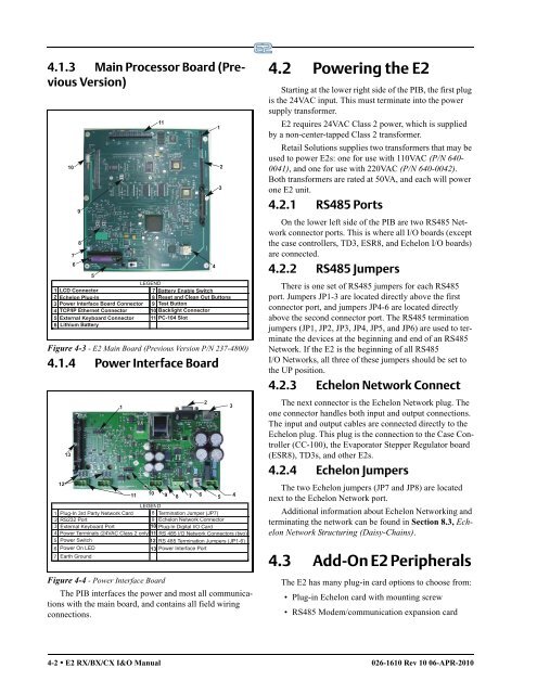
4.1.3 Main Processor Board (Previous<br />
Version)<br />
Figure 4-3 - <strong>E2</strong> Main Board (Previous Version P/N 237-4800)<br />
4.1.4 Power Interface Board<br />
Figure 4-4 - Power Interface Board<br />
The PIB interfaces the power and most all communications<br />
with the main board, and contains all field wiring<br />
connections.<br />
4.2 Powering the <strong>E2</strong><br />
Starting at the lower right side of the PIB, the first plug<br />
is the 24VAC input. This must terminate into the power<br />
supply transformer.<br />
<strong>E2</strong> requires 24VAC Class 2 power, which is supplied<br />
by a non-center-tapped Class 2 transformer.<br />
Retail Solutions supplies two transformers that may be<br />
used to power <strong>E2</strong>s: one for use with 110VAC (P/N 640-<br />
0041), and one for use with 220VAC (P/N 640-0042).<br />
Both transformers are rated at 50VA, and each will power<br />
one <strong>E2</strong> unit.<br />
4.2.1 RS485 Ports<br />
On the lower left side of the PIB are two RS485 Network<br />
connector ports. This is where all I/O boards (except<br />
the case controllers, TD3, ESR8, and Echelon I/O boards)<br />
are connected.<br />
4.2.2 RS485 Jumpers<br />
There is one set of RS485 jumpers for each RS485<br />
port. Jumpers JP1-3 are located directly above the first<br />
connector port, and jumpers JP4-6 are located directly<br />
above the second connector port. The RS485 termination<br />
jumpers (JP1, JP2, JP3, JP4, JP5, and JP6) are used to terminate<br />
the devices at the beginning and end of an RS485<br />
Network. If the <strong>E2</strong> is the beginning of all RS485<br />
I/O Networks, all three of these jumpers should be set to<br />
the UP position.<br />
4.2.3 Echelon Network Connect<br />
The next connector is the Echelon Network plug. The<br />
one connector handles both input and output connections.<br />
The input and output cables are connected directly to the<br />
Echelon plug. This plug is the connection to the Case Controller<br />
(CC-100), the Evaporator Stepper Regulator board<br />
(ESR8), TD3s, and other <strong>E2</strong>s.<br />
4.2.4 Echelon Jumpers<br />
The two Echelon jumpers (JP7 and JP8) are located<br />
next to the Echelon Network port.<br />
Additional information about Echelon Networking and<br />
terminating the network can be found in Section 8.3, Echelon<br />
Network Structuring (Daisy-Chains).<br />
4.3 Add-On <strong>E2</strong> Peripherals<br />
The <strong>E2</strong> has many plug-in card options to choose from:<br />
• Plug-in Echelon card with mounting screw<br />
• RS485 Modem/communication expansion card<br />
4-2 • <strong>E2</strong> RX/BX/CX I&O <strong>Manual</strong> 026-1610 Rev 10 06-APR-2010