A R B O R Wood Stove - Avalon
A R B O R Wood Stove - Avalon
A R B O R Wood Stove - Avalon
- No tags were found...

Create successful ePaper yourself
Turn your PDF publications into a flip-book with our unique Google optimized e-Paper software.
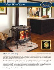
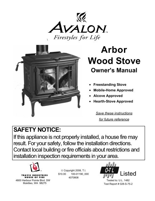
\A r b o r<strong>Wood</strong> <strong>Stove</strong>Owner's Manual• Freestanding <strong>Stove</strong>• Mobile-Home Approved• Alcove Approved• Hearth-<strong>Stove</strong> ApprovedSave these instructionsfor future referenceSAFETY NOTICE:If this appliance is not properly installed, a house fire mayresult. For your safety, follow the installation directions.Contact local building or fire officials about restrictions andinstallation inspection requirements in your area.4800 Harbour Pointe Blvd. SWMukilteo, WA 98275© Copyright 2008, T.I.Listed$10.00 100-01190_0004070808Tested to: U.L. 1482Test Report # 028-S-75-2
2 IntroductionIntroductionWe welcome you as a new owner of an Arbor wood-burning stove. In purchasing an Arbor you havejoined the growing ranks of concerned individuals whose selection of an energy system reflects both aconcern for the environment and aesthetics. The Arbor is one of the finest appliances the world over.This manual will explain the installation, operation, and maintenance of this appliance. Please familiarizeyourself with the Owner's Manual before operating your appliance and save the manual for futurereference. Included are helpful hints and suggestions which will make the installation and operation ofyour new appliance an easier and more enjoyable experience. We offer our continual support andguidance to help you achieve the maximum benefit and enjoyment from your appliance.Important InformationNo other <strong>Avalon</strong> Arbor appliance has the same serialnumber as yours. The serial number is stamped ontothe label on the back of the appliance.This serial number will be needed in case you requireservice of any type.Model: <strong>Avalon</strong> ArborSerial Number:Purchase Date:Purchased From:Register your warranty online at:traviswarranty.comOr, mail your warranty card to:Travis Industries House of Fire4800 Harbour Pointe Blvd. SWMukilteo, WA 98275Save Your Bill of Sale.To receive full warranty coverage, you willneed to show evidence of the date youpurchased your heater. Do not mail your Billof Sale to us.We suggest that you attach your Bill of Saleto this page so that you will have all theinformation you need in one place should theneed for service or information occur.© Travis Industries 100-01190_000 4070808
Table of Contents 3General InformationOperating Your Appliance (continued)Introduction & Important Information...................... 2 Ash Removal.................................................... 24Safety Precautions ............................................ 4Ashpan Removal .......................................... 24Features & Specifications.................................... 6 Blower Operation .............................................. 25Re-Loading the <strong>Stove</strong>......................................... 25<strong>Stove</strong> InstallationOvernight Burn ................................................. 25Planning the Installation...................................... 7Normal Operating Sounds ................................... 25Preparation for Installation .............................. 7Hints for Burning ............................................... 26<strong>Stove</strong> Installation Considerations ..................... 7Selecting <strong>Wood</strong>................................................. 26Floor Protection Requirements ............................. 8Why Dry <strong>Wood</strong> is Key.................................... 26<strong>Stove</strong> Placement Requirements ........................... 8<strong>Wood</strong> Cutting and Storage.............................. 26Clearances ...................................................... 8Burn Procedure Pictorial Overview........................ 27Top View - Straight Installation ........................ 9Troubleshooting ................................................ 29Top View - Corner Installation ......................... 9Bypass Handle Installation .................................. 10 Maintaining Your ApplianceRear Vent Configuration ..................................... 10 Daily Maintenance (while stove is in use) ............... 30Chimney Connector Requirments ......................... 11 Remove Ash (if necessary) ............................. 30Chimney Requirements ...................................... 12 Clean the Glass (if necessary)......................... 30Chimney Termination Requirements...................... 13 Monthly Maintenance (while appliance is in use) ...... 31Outside Air Requirements ................................... 13 Door and Glass Inspection.............................. 31Alcove Installation Requirements .......................... 14 Creosote - Formation and Need for Removal...... 31Mobile Home Requirements ................................ 15 Clean the Combustion Brick............................ 32INSTALLATION DIAGRAMSYearly Maintenance ........................................... 32Standard Ceiling with a Factory Built Chimney .... 16 Touch Up Paint ............................................ 32Cathedral Ceiling with a Factory Built Chimney ... 16 Cleaning the Air Duct and Blower (if applicable) .. 32Hearth <strong>Stove</strong> Positive Connection .................... 17 Door Parts ....................................................... 34Hearth <strong>Stove</strong> Direct Connection....................... 17 Replacing the Glass ...................................... 34Interior or Exterior Masonry Chimney ................ 18 Replacing the Door Gasket ............................. 34Replacing the Loading Lid Gasket .................... 34Operating Your ApplianceReplacing the Door Handle ............................. 34Safety Notice.................................................... 19Firebox Parts.................................................... 35Operating the <strong>Stove</strong> when it is Hot ................... 19Brick Removal & Replacement ........................ 35Before Your First Fire ......................................... 19Combustor Removal & Replacement ................ 35Curing the Paint ........................................... 19Over-Firing the <strong>Stove</strong> .................................... 19 WarrantyOpening the Doors ............................................ 20 Warranty ......................................................... 34Bypass Operation.............................................. 21 Listing InformationLoading Lid Operation ........................................ 21Listing Information ............................................. 38Starting a Fire................................................... 22Adjusting the Burn Rate ...................................... 23Optional EquipmentApproximate Air Control Settings ..................... 23 Rear Blower Installation ...................................... 39IndexIndex .............................................................. 40© Travis Industries 100-01190_000 4070808
4 Safety PrecautionsThe viewing door must beclosed and latched duringoperation.Never block free airflow throughthe air vents on this appliance.GasGasoline or other flammableliquids must never be used tostart the fire or "Freshen Up" thefire. Do not store or usegasoline or other flammableliquids in the vicinity of thisappliance.This appliance is designed andapproved for the burning of cordwood only. Do not attempt toburn any other type of fuel otherthan cord wood in thisappliance, it will void allwarranties and safety listings.ASHESAshes must be disposed in ametal container with a tight lidand placed on a noncombustiblesurface well awayfrom the home or structure.Do not touch the appliance whileit is hot and educate all childrenof the danger of a hightemperatureappliance. Youngchildren should be supervisedwhen they are in the same roomas the appliance.36"Keep furniture, drapes, curtains,wood, paper, and othercombustibles a minimum of 36"away from the front of theappliance.This appliance must be properlyinstalled to prevent thepossibility of a house fire. Theinstructions must be strictlyadhered to. Do not usemakeshift methods orcompromise in the installation.OkContact your local buildingofficials to obtain a permit andinformation on any installationrestrictions or inspectionrequirements in your area.Notify your insurance companyof this appliance as well.Inspect the chimney connectorand chimney at least twicemonthly and clean if necessary.Creosote may build up andcause a house fire.Do not connect this appliance toany chimney serving anotherappliance.TypeHTClayLinerThis appliance must beconnected to a listed hightemperature (UL 103 HT)residential type chimney or anapproved masonry chimney witha standard clay tile, or stainlesssteel liner.© Travis Industries 100-01190_000 4070808
Safety Precautions 5MobileHomeWhen installed in a mobilehome, this appliance must bebolted to the floor, have outsideair, and not be installed in thebedroom (Per H.U.D.requirements). Check with localbuilding officials.Do not place clothing or otherflammable items on or near thisappliance.Never try to repair or replaceany part of this appliance unlessinstructions are given in thismanual. All other work must bedone by a trained technician.Allow the appliance to coolbefore carrying out anymaintenance or cleaning.Do not make any changes ormodifications to an existingmasonry fireplace or chimney toinstall this appliance.Do not make any changes to theappliance to increasecombustion air.Overfiring the appliance maycause a house fire. If a unit orchimney connector glows, youare overfiring.Maintain the door and glass sealand keep them in goodcondition.Avoid placing wood against theglass when loading. Do notslam the door or strike the glass.Do not use a grate or otherdevice to elevate the fire off ofthe firebox floor. Burn the firedirectly on the bricks.ThisManualDo not throw this manual away.This manual has importantoperating and maintenanceinstructions that you will need ata later time. Always follow theinstructions in this manual.Travis Industries, Inc. grantsno warranty, implied orstated, for the installation ormaintenance of yourappliance, and assumes noresponsibility of anyconsequential damage(s).© Travis Industries 100-01190_000 4070808
6 Features & SpecificationsInstallation Options• Freestanding• Freestanding in an Alcove• Freestanding in a Mobile Home• Freestanding Hearth <strong>Stove</strong>Heating SpecificationsFeatures• EPA Phase II Approved• 2.3 Cubic Foot Firebox Volume• Single Air Control• Accepts Logs Up to 21” Long• Cast Iron Construction• Heavy Duty Refractory Firebrick• Optional High-Tech BlowerApproximate Maximum Heating Capacity (in square feet)* Up to 2,000Maximum BTU's per Hour (Cord <strong>Wood</strong> Calculation) 73,100Overall Efficiency (Oregon Method) 70 %Maximum Burn TimeUp to 12 Hours* Heating capacity will vary depending on the home's floor plan, degree of insulation, and the outsidetemperature. It is also affected by the quality and moisture level of the fuel.Dimensions22-7/8"17"2-5/8"27-1/4"5-3/4"27-3/4"25-1/4"Weight: 375 Lbs.NOTE:Measure side, corner, and backclearances from the stove top.Emissions2.4 Grams Per Hour (EPA Phase II Approved) – Tests conducted by OMNI-Test Laboratories.Figure 1© Travis Industries 100-01190_000 4070808
<strong>Stove</strong> Installation (for qualified installers only) 7SAFETY NOTICE:Please read this entire manual before you install and use your new room heater. Failureto follow instructions may result in property damage, bodily injury, or even death.Contact local building or fire officials about restrictions and installation inspectionrequirements in your area.Always use gloves when operating a hot stove. The door handles, loading lid, bypass handle, and othercomponents become very hot during normal use.Planning The InstallationWe suggest that you have an authorized Travis Industries dealer install your stove. If you install thestove yourself, your authorized dealer should review your installation plans.Check with local building officials for any permits required for installation of this stove and notify yourinsurance company before proceeding with installation.Preparation for Installation• Check for damage to the exterior of the stove.• Check the interior of the firebox to verify all components are in place.The stove can be lightened for transportation by removing the doors, loading lid, and firebricks. Replacethese components before operation.• Install the bypass handle (included in the owner’s pack - see page 10).<strong>Stove</strong> Installation ConsiderationsThe table below details the six most common types of installations and the considerations for each type.Alternative methods of installation are available if they comply with local building codes.Installation TypeStandard Ceiling with a Factory Built Chimney(Page 16)Cathedral Ceiling with a Factory Built Chimney(Page 16)Hearth <strong>Stove</strong> Positive Connection(Page 17)Hearth <strong>Stove</strong> Direct Connection(Page 17)Interior Masonry Chimney(Page 18)Considerations• Requires ceiling and roof penetration• Provides best draft• Cathedral style chimney support required• Provides best draft• Utilizes existing masonry fireplace (not approved for zeroclearance (metal) fireplaces)• Provides good draft due to full reline• Easier to clean than direct or horizontal hearth stove• Utilizes existing masonry fireplace (not approved for zeroclearance (metal) fireplaces)• Requires construction of a "block-off plate"• Draft reduced due to elbows & chimney cross section• Utilizes existing masonry chimney (not approved for zeroclearance (metal) fireplaces)© Travis Industries 100-01190_000 4070808
8 <strong>Stove</strong> Installation (for qualified installers only)Floor Protection Requirements• Floor protection must extend 6" to the sides and rear of the stove and 16" to the front of the stove39.25” wide by 44.875" deep - see Figure 2 and Figure 3).• Floor protection must be non-combustible and at least .018" thick (26 guage).<strong>Stove</strong> Placement RequirementsClearances may be reduced by methods specified in NFPA 211, listed wall shields, pipe shields, orother means approved by local building or fire officials.• <strong>Stove</strong> must be placed so that no combustibles are within, or can swing within (e.g. drapes, doors), 36"of the front of the stove• Must maintain the clearances to combustibles listed below (drywall, furniture, etc.):Clearances• The following clearances must be met (see Figure 2 and Figure 3)Minimum ClearanceSinglewallConnectorSinglewallConnector withPipe Shield**ReducedClearance*A Sidewall to stove 18.00” 18.00” 18.00”B Backwall to stove 27.25” 17.25” 20.75”C Cornerwall to stove 19.00” 14.00” 14.00”D Connector to sidewall 28.75” 28.75” 28.25”E Connector to backwall 21.00” 11.00” 14.00”F Connector to cornerwall 23.00” 18.00” 17.50”*Reduced clearance installations require one of the chimneys and connectors listed below:AMERI-TEC model DCC connector with AMERI-TEC UL 103 HT chimneyDURAVENT model DVL connector with DURAVENT UL 103 HT chimneyGSW Super Chimney Twenty-One connected directly to applianceI.C.C. Excel HP connector with I.C.C. UL 103 HT chimneyMETALFAB model DW connector with METALFAB UL 103 HT chimneyOLIVER MACLEOD PROVENT model PV connector with OLIVER MACLEOD UL 103 HT chimneySECURITY model DP connector with SECURITY UL 103 HT chimneySELKIRK model DSP connector with SELKIRK UL 103 HT chimneyStandard Masonry Chimney with any one of the above listed connectorsNOTE: Reduced clearance connectors may not connect to the flue collar – an appliance adaptermay be required.NOTE: Mobile Home installations must use the reduced clearance connector and clearanceslisted above.NOTE: Standard residential installations with reduced clearance connector may use the“Connector to Wall” clearance determined by the connector manufacturer if approved bylocal code. This clearance is established by the connector manufacturer and falls underthe connector manufacturer’s listing. “<strong>Stove</strong> to Wall” clearances must always be met.** The pipe shield must meet NFPA 211 guidelines (such as the HomeSaver® <strong>Stove</strong>pipe shield) andmust extend from the flue collar to a location 16” below the ceiling.© Travis Industries 100-01190_000 4070808
<strong>Stove</strong> Installation (for qualified installers only) 9Minimum Flue Center 31-3/4"Top View -Straight InstallationBack WallClearance BTop View -Corner InstallationClearance E6” Min.27-1/4”2-5/8”3-1/4” 6” Min.22-7/8”16” Min.Floor ProtectionClearance DClearance ASide WallNOTE: vent diametermay vary depending onbrand and model.Typical Flue CenterSinglewall 24"Reduced Clearance 17.5"Singlewall w Pipe Shield 14"Measure rear and side clearances fromthe nearest edge of the stove top.Measure front clearances from theface of the stove (door opening).Typical Flue CenterSinglewall 26"Reduced Clearance 21"Singlewall w Pipe Shield 21"Figure 2Corner WallClearance F27-1/4”6” Min.2-5/8”3-1/4”6” Min.22-7/8”16” Min.Floor ProtectionClearance CCorner WallNOTE: vent diametermay vary depending onbrand and model.Measure rear and side clearances fromthe nearest edge of the stove top.Measure front clearances from theface of the stove (door opening).© Travis Industries 100-01190_000 4070808Figure 3
10 <strong>Stove</strong> Installation (for qualified installers only)Bypass Handle InstallationThe bypass handle is shipped inside the owner’s pack (along with a 1/8” hex wrench). With the setscrews loosened, line up the bypass handle with the bypass rod (Figure 4). Press back on the bypasslever and slide the handle into place. NOTE: Several washers may be included on the bypass rod toact as spacers – do not remove these washers . Once in place, secure the handle by tighteningthe two set screws. Make sure the set screws are properly located over the holes in the bypass rod.When tightened, the set screws will submerge below the surface of the handle (Figure 4).Rear Vent ConfigurationFigure 4The rear vent configuration is only for masonry fireplace installations (hearth stove). All steel chimneyapplications require the top vent configuration.The vent (chimney connector) may be directed to the rear of the appliance when installed into a masonryfireplace. See Figure 5 for details.Open the bypass - thisallows for access to thenut under the flue collar.The flue collar is held in place with three boltsand two nuts. Use two 7/16" open-endwrenches to remove the bolts and nuts.7/16" WrenchRemove the flue collar and rotate it to the rear.Use the existing bolts and nuts to attach thesides of the flue. For the center connectionuse the bolt and acorn nut included in theowner's pack.NOTE: Make sure the gasketunderneath the flue collar is properlylocated and seals the flue collar whenit is installed.Figure 5© Travis Industries 100-01190_000 4070808
<strong>Stove</strong> Installation (for qualified installers only) 11Chimney Connector Requirements• Chimney connector is required from the flue collar of the stove to the factory-built chimney (seeFigure 7) or masonry chimney (see Figures 13, 14, and 15).• The chimney connector must be 6” diameter and a minimum 24 gauge black steel, 26 gauge bluedsteel, or one of the reduced-clearance connectors listed on page 8.NOTE: Aluminum or galvanized steel is not allowed – these materials can not withstand the fluetemperatures and may give off toxic fumes when heated.NOTE: Standard residential installations may use single-wall connector (Mobile-Homes may not).• The chimney connector may not pass through a ceiling, attic, roof, closet, or any other concealedspace (use listed UL 103 HT chimney – see “Chimney Requirements for details). DO NOT USECONNECTOR PIPE AS CHIMNEY.• The chimney connector should be as short and direct as possible. No more than 180 o of elbows (two90 o elbows, or two 45 o & one 90 o elbow, etc.) may be used for the entire system (connector andchimney).. Horizontal runs should slope upwards 1/4” per foot and be a maximum 36” long.• The chimney connector must be installed with the crimped end pointing downwards (see Figure 7).This prevents creosote from leaking to the exterior of the pipe.• The chimney connector must be fastened to the stove and each adjoining section (and chimney).• In cases where the chimney connector must be passed through a combustible wall or partition, thefollowing NFPA 211 method may be used if local building codes permit. Check with local authoritiesbefore installation to insure all necessary requirements have been met. Figure 6 details a wall passthroughbased on the NFPA 211 standard.NFPA 211 Wall Pass-Through(see NFPA 211 for a full description)BrickFire Clay Thimble12” Min.12” Min.Combustible MaterialsFigure 6© Travis Industries 100-01190_000 4070808
12 <strong>Stove</strong> Installation (for qualified installers only)Chimney Requirements• DO NOT CONNECT THIS UNIT TO A CHIMNEY FLUE SERVING ANOTHER APPLIANCE.• UL 103 HT Chimney must be used from the first ceiling or floor penetration to the chimney cap.• Use 6" diameter type UL 103 HT chimney from one manufacturer (do not mix brands) or codeapproved masonry chimney with a flue liner.• Chimney must be fastened to each adjoining section.• Follow the chimney manufacturer's clearances and requirements.• Use the chimney manufacturer's fire stops, attic guards, roof supports, and flashings when passingthrough a ceiling• No more than 180 o of elbows (two 90 o elbows, or two 45 o & one 90 o elbow, etc.) may be used for theentire system (connector and chimney).NOTE: Additional elbows may be allowed if draft is sufficient. Whenever elbows are used the draft isadversely affected. Additional chimney height may be required to boost draft.Chimney Cap(See the section "ChimneyTermination Requirements"for more details)Minimum System 15'Maximum System 33'Factory BuiltChimney SectionsFloor Penetration Equipment(Attic Radiation Shield withChimney Support)ConnectorOn singlewall pipethe crimped endpoints downward.} }Roof Penetration Equipment(Roof Radiation Shield,}Flashing, Storm Collar)Minimum Air Space toCombustibles (SeeChimney Manufacturer'sInstructions - usually 2")DraftingPerformanceFloorProtectionConnector Clearance(as outlined in this manual)Figure 7This appliance relies upon natural draft to operate. External forces, such as wind,barometric pressure, topography, or factors of the home (negative pressure from exhaustfans, chimneys, air infiltration, etc.), may adversely affect draft. Travis Industries can not beresponsible for external forces leading to less than optimal performance.© Travis Industries 100-01190_000 4070808
<strong>Stove</strong> Installation (for qualified installers only) 13Chimney Termination Requirements• Must have an approved cap (to prevent water from entering)• Must not be located where it will become plugged by snow or other material• Must terminate at least 3' above the roof and at least 2' above any portion of the roof within 10' (seeFigure 8)Slanted RoofsFlat RoofsChimney mustextend 3'above the roofChimney must extend 2'above any portion of the roofwithin 10' of the chimneyChimney mustextend 3'above the roofOutside Air RequirementsChimney must extend 2'above any portion of the roofwithin 10' of the chimney• Required for mobile homes and in certain localities (check with building officials)• Must not be drawn from an enclosed space (garage, unventilated crawl space)• Requires 3” aluminum duct (do not use plastic “dryer-vent”) and a hose-clamp for securing to thestove. Maximum 4’ length. NOTE: A 10’ length is allowed if using 4” diameter duct (use a 3” to 4”converter).• If using the optional blower, you may need to “ovalize” the duct to route it under the blower box.Figure 8A screen is required to preventrodents from entering.Botttom of <strong>Stove</strong>3” Air Duct (max. 4’ length)Air may be drawn from a ventilated crawl space.Use a hose clamp to secure thealuminum air duct to the air inletflange on the stove.Outside air entrance must be placed so itdoes not become blocked by snow.Air Duct (3” Dia.)Figure 9© Travis Industries 100-01190_000 4070808
14 <strong>Stove</strong> Installation (for qualified installers only)Alcove Installation RequirementsWhenever the stove is placed in a location where the ceiling height is less than 8' tall, it is considered analcove installation. Because of the reduced height, the special installation requirements listed below mustbe met.• Chimney connector and chimney must be one of the following types:AMERI-TEC model DCC connector with AMERI-TEC UL 103 HT chimneyDURAVENT model DVL connector with DURAVENT UL 103 HT chimneyGSW Super Chimney Twenty-One connected directly to applianceI.C.C. Excel HP connector with I.C.C. UL 103 HT chimneyMETALFAB model DW connector with METALFAB UL 103 HT chimneyOLIVER MACLEOD PROVENT model PV connector with OLIVER MACLEOD UL 103 HT chimneySECURITY model DP connector with SECURITY UL 103 HT chimneySELKIRK model DSP connector with SELKIRK UL 103 HT chimneyStandard Masonry Chimney with any one of the above listed connectorsNOTE: Reduced clearance connectors may not connect to the flue collar – an appliance adapter may be required.• The clearances below must be met:Minimum Clearance(See Figure 10 below)CombustibleAlcoveA Sidewall to stove 18.00"B Backwall to stove 20.75"D Connector to sidewall 28.25"E Connector to backwall 14.00"G Maximum depth of alcove 48.00"H Minimum width of alcove 63.25"J Minimum height of alcove 84.00"adejbhgFigure 10© Travis Industries 100-01190_000 4070808
Mobile Home Requirements<strong>Stove</strong> Installation (for qualified installers only) 15• Outside air must be installed - see "Outside Air Requirements" on page 13• Chimney connector and chimney must be one of the following types:AMERI-TEC model DCC connector with AMERI-TEC UL 103 HT chimneyDURAVENT model DVL connector with DURAVENT UL 103 HT chimneyGSW Super Chimney Twenty-One connected directly to applianceI.C.C. Excel HP connector with I.C.C. UL 103 HT chimneyMETALFAB model DW connector with METALFAB UL 103 HT chimneyOLIVER MACLEOD PROVENT model PV connector with OLIVER MACLEOD UL 103 HT chimneySECURITY model DP connector with SECURITY UL 103 HT chimneySELKIRK model DSP connector with SELKIRK UL 103 HT chimneyStandard Masonry Chimney with any one of the above listed connectorsNOTE: Reduced clearance connectors may not connect to the flue collar – an appliance adapter may be required.• <strong>Stove</strong> placement must maintain the following clearances to combustibles (drywall, furniture, etc.)EBDAMinimum Clearance(See the illustration above)Measure clearances from thenearest edge of the stove top.CFCReduced ClearanceConnectorA Sidewall to stove 18.00”B Backwall to stove 20.75”C Cornerwall to stove 14.00”D Connector to sidewall 28.25”E Connector to backwall 14.00”F Connector to cornerwall 17.50”Figure 11• If using offsets, use the connector clearance listed in Figure 12,not the connector manufacturer's clearance.• The appliance must be secured to the floor (consult yourbuilding official). Secure the outside air boot to the floor andstove to insure the stove does not dislocate.• Mobile home installations require a spark arrester at thechimney termination.• The appliance must be grounded to the chassis of the mobilehome (consult your building official).• WARNING:DO NOT INSTALL IN SLEEPING ROOM.• CAUTION:THE STRUCTURAL INTEGRITY OF THE MOBILEHOME FLOOR, WALL, AND CEILING/ROOF MUST BEMAINTAINED.12” Min.Connector Clearance(as outlined above)<strong>Stove</strong> Clearance(as outlined above)Figure 12© Travis Industries 100-01190_000 4070808
16 <strong>Stove</strong> Installation (for qualified installers only)Standard Ceilingwith a FactoryBuilt ChimneyChimney Cap(See the section "ChimneyTermination Requirements"for more details)Chimney SectionsInsulationFollow the chimneymanufacturer's instructionsand clearances for floorpenetrations. A ceilingsupport is required, an atticinsulation shield is requiredwhere insulation is present.Chimney Connector Sections}} Follow the chimneymanufacturer's instructionsand clearances for roofpenetrations. A storm collarand flashing are required(some require a radiationshield).Minimum Air Space toCombustibles (SeeChimney Manufacturer'sInstructions - usually 2")Minimum 15'Maximum 33'Cathedral Ceilingwith a FactoryBuilt ChimneyFloor Protection(See the section "FloorProtection Requirements"for more details)Chimney Cap(See the section "ChimneyTermination Requirements"for more details)Chimney SectionsMinimum Air Space toCombustibles (See ChimneyManufacturer's Instructions -usually 2")ChimneyConnectorSections}<strong>Stove</strong> Clearances(See the section "<strong>Stove</strong>Placement Requirements"for more details)Follow the chimneymanufacturer's instructionsand clearances for roofpenetrations. A stormcollar, flashing, andcathedral-style chimneysupport are required(some require a radiationshield).Figure 13Minimum 15'Maximum 33'Floor Protection(See the section "FloorProtection Requirements"for more details)<strong>Stove</strong> Clearances(See the section "<strong>Stove</strong>Placement Requirements"for more details)Figure 14© Travis Industries 100-01190_000 4070808
<strong>Stove</strong> Installation (for qualified installers only) 17Hearth <strong>Stove</strong>PositiveConnectionNOTE:Most factory-builtchimney manufacturersmake stainless steelchimney liners, eitherflexible or rigid. Thisprovides a wide varietyof installation options.Make sure to follow themanufacturer'sinstructions forinstallation and support.Hearth <strong>Stove</strong> DirectConnectionNOTE:Direct connections requireinstallation of an airtight,non-combustible block-offplate or damper adapter.NOTE: The entire fireplace andchimney must be clean, undamaged,and meet all local building codes(UBC, etc.). Damage must berepaired prior to installation. Thechimney must be 15' to 33' tall.CombustibleMantleFloor Protection(See the section"Floor ProtectionRequirements"for more details)Min. 36"NOTE: The chimney must have a claytile liner. If it does not, the installationmust use a positive connection (fullreline). The entire fireplace andchimney must be clean, undamaged,and meet all local building codes (UBC,etc.). Damage must be repaired priorto installation. The chimney must be15' to 33' tall.Combustible MantleFloor Protection(See the section "FloorProtection Requirements"for more details)Min. 36"Cap and flashingprevents water fromenteringThe liner must bestainless steel connectoror flexible vent. Followthe liner manufacturer'sinstructions for installationand support.Airtight InsulatedClean-OutRemove damperor wire it openSee the section"<strong>Stove</strong> PlacementRequirements" forminimum clearancesrequired.ClayLinerAirtightInsulatedClean-OutRemove damperor wire it openBlock-off plate ordamper adapterFigure 15Stainless steelchimney connectormust Extend 1' pastthe block-off plate orto the flue linerSee the section"<strong>Stove</strong> PlacementRequirements" forminimum clearancesrequired.Figure 16© Travis Industries 100-01190_000 4070808
18 <strong>Stove</strong> Installation (for qualified installers only)Interior or ExteriorMasonry ChimneyNOTE:This type of installationrequires a UBC approvedmasonry connector orother method approved bythe NFPA 211 standard.See Chimney ConnectorRequirements on page 11for further details.NOTE: The chimney must have aclay tile liner. If it does not, theinstallation must use a positiveconnection (full reline). Theentire fireplace and chimney mustbe clean, undamaged, and meetall local building codes (UBC,etc.). Damage must be repairedprior to installation. The chimneymust be 15' to 33' tall.See the section "<strong>Stove</strong>Placement Requirements" forminimum clearances required.Min. 18"clearanceto ceilingClay LinerThis type ofinstallation requiresa UBC approvedmasonry connectoror other methodapproved by theNFPA 211 standard.Chimney connector sectionsFull Re-Line(recommended)See the section"Floor ProtectionRequirements"Make sure theclean-out seals inplace.Figure 17© Travis Industries 100-01190_000 4070808
Operating Your Appliance 19Safety NoticeIf this appliance is not properly installed, a house fire may result. For your safety, follow the installationdirections. Contact local building or fire officials about restrictions and installation inspectionrequirements in your area.Read and follow all of the warnings on pages 4 and 5 of this manual.Operating the <strong>Stove</strong> when it is HotAlways use gloves when operating a hot stove. The door handles, loading lid, bypass handle, and othercomponents become very hot during normal use.Before Your First Fire Verify the InstallationBefore starting the stove, verify that the stove is properly installed and all of the requirements in thismanual have been followed.Keep all flammable materials 36" away from the front of the stove (drapes, furniture, clothing, etc.).Curing the PaintThis heater uses a heat-activated paint that will emit some fumes while startingthe first fire. Open doors and windows to the room to vent these fumes. Thistypically lasts two to four hours. You may also notice oil burning off of the interiorof the heater. This rust-stopping agent will soon dissipate.Door Gasket - The door gasket might adhere to the paint on the front of theheater. Leave the door slightly ajar for the first fire and be careful when openingthe door after the first fire.Over-Firing the <strong>Stove</strong>2 to 4 hoursThis stove was designed to operate at a high temperature. But due to differences in vent configuration,fuel, and draft, this appliance can be operated at an excessive temperature. If the stove top or other areastarts to glow red, you are over-firing the stove. Shut the air control down to low and allow the stove tocool before proceeding.Over-firing may lead to damage of plated surfaces. If you are uncertain of over-firing conditions, wesuggest placing a stove thermometer (e.g. Rutland® Model 710) directly over the door on the stove top -temperatures exceeding 800° are generally considered over-firing and will void the warranty.© Travis Industries 100-01190_000 4070808
20 Operating Your ApplianceOpening the DoorsTypically the doors are only opened to start the fire. Use the Loading Lid to re-load the stove.Open the bypass first (this preventssmoke from entering the room).A door latch tool is included foroperation when the door latch ishot. Hang the tool on the aircontrol when not in use.Open the latchSwing thedoors open.WARNING: Do not swing the doors past 90°. This may causethe doors to strike the body of the stove and cause damage.NOTE: When closing the doors, close the left door first. Thenshut the right door and tighten the latch.The door becomes hot during use. Use a glove to open the door if the handle is hot.To prevent smoke from entering the room, open the bypass before opening the door (see following pagefor directions). You can also open the door a small amount and let air enter the firebox.© Travis Industries 100-01190_000 4070808
Bypass OperationOperating Your Appliance 21The bypass controls the flow of smoke inside the heater. When open, smoke goes directly up the flue,creating more draft. When closed, the smoke goes through the combustor, utilizing the secondarycombustion system and making the heater more efficient. When starting or re-loading the stove, open the bypass. Once the stove reaches full temperature – typically 45 minutes, close the bypass.To open the bypass, push on thelever and rotate the handle up.To close the bypass, simply rotate thehandle down.Bypass OPENUsed for startingand re-loadingBypass CLOSEDUsed for normaloperationLoading Lid OperationbOpen the bypass first (thishelps prevent smoke fromentering the room).cOpen the lid 1" for a fewseconds to allow air toenter the firebox.dLift the lid upward.WARNING: This partbecomes hot - use gloves.A log poker isprovided with thisstove. It attacheswith a clip to to theback of the stove.aOpen the air control and allow air to flowinto the firebox for 30 seconds.Do not wear loose clothing while re-loading the stove. Any item dangling above the opening may ignite.Carefully close the loading lid after use. Allowing it to “slam” shut may damage the stove.© Travis Industries 100-01190 4110915
22 Operating Your ApplianceStarting a FireSince the dawn of time man has debated the best way to start a fire. Some use the boy-scout "tee-pee",some prefer the "tic-tac-toe" stack. Either way, review the hints and warnings below to ensure proper firestarting.• Make sure the air control and by-pass are pulled out. If additional air is needed, open the doors 1/4"during the first five minutes of start-up.Open the bypass. Leave itopen until the stove isHOT (up to 45 minutes).Pull the air controlall the way out.ALLOW THE STOVE TO FULLY HEAT PRIOR TO SHUTTING THE BYPASSWe occasionally get calls regarding a smokey stove during start-up. The primary cause isshutting the bypass prior to the stove becoming hot. If you shut the bypass too early, thecombustor will not work (the combustor must be hot for it to work properly). This in turn will slowcombustion and will lead to a smokey fire.Never use gasoline, gasoline-type lantern fuel, kerosene, charcoal lighter fluid, or similar liquids to startor "freshen up" a fire in this stove. Keep all such liquids well away from the stove while it is in use.If using a firestarter, use only products specifically designed for stoves - follow the manufacturer'sinstructions carefully.If the smoke does not pass up the chimney, ball up one sheet of newspaper, place it in the center of thefirebox and light it. This should start the chimney drafting (this eliminates "cold air blockage").Use plenty of kindling to ensure the stove reaches a proper temperature. Once the kindling is burningrapidly, place a few larger pieces of wood onto the fire.Starting a “Top-Down Fire”One particularly successful method for starting a fire is tostack several large pieces of wood in the center of the stove(see the illustration to the right). Then place a several wadsof newspaper in the center with kindling on top. When youlight the newspaper this “top-down” fire will burn its way tothe center, igniting the larger pieces. With some practice,this method should work for you.© Travis Industries 100-01190_000 4070808
Adjusting the Burn RateOperating Your Appliance 23Use the air control slider to control the burn rate of the stove. See the illustration below for details.Use the air control tochange the burn rate.Low BurnHigh Burn(air control closed) (air control open)Approximate Air Control SettingsOvernight BurnMedium BurnMedium High BurnHigh BurnFully in1/32" to 5/32” Open5/32” to Fully OpenFully Open (Pulled Out)The air control becomes hot during operation - use gloves or a tool to prevent burns.The air control may take several minutes to influence the burn rate. When making adjustments, youmay wish to let the stove burn for 10 minutes to gauge performance.© Travis Industries 100-01190_000 4070808
24 Operating Your ApplianceAsh RemovalASHESAshpan RemovalAshes should be placed in a metal container with a tight fitting lid. The closed container of ashesshould be placed on a noncombustible floor or on the ground, away from all combustiblematerials, pending final disposal. If the ashes are disposed of by burial in soil or otherwise locallydispersed, they should be retained in the closed container until all cinders have thoroughlycooled.The ashpan must be properly inserted and fully closed during operation. Failure to fully close and sealthe ashpan may lead to an over-fired stove, negating the warranty and creating a safety hazard.The ashpan may only be removed after the stove has fully cooled.Lift up on theashlip and slidethe ashpanforward.Twist the ashpanhandle clockwise.A handle is providedon the ashpan toremove the ashes.© Travis Industries 100-01190_000 4070808
Operating Your Appliance 25Blower OperationThe blower is available to assist the convection chamber in distributing heat to your home. The directionsbelow detail the options you have with the blower and the best method for operation.OFFTurn the dial all the way counterclockwiseuntil it clicks off.HIGHThe high position is all the way counterclockwise,without clicking off.LOWTurn the dial all theway clockwise.BLOWERCONTROL STARTOFFRUNBLOWERCONTROL STARTOFFRUN STARTOFF RUN BLOWERCONTROLRoute the power cord in a location where it will not come in contact with the appliance or become hot.Re-Loading the <strong>Stove</strong>Follow the directions below to minimize smoke spillage while re-loading the stove.1 Open the air control all the way (pull it out). Open the bypass (rotate it down).2 Open the loading lid. Let the airflow inside the firebox stabilize before opening the loading lid fully.3 Load wood onto the fire.Overnight BurnThis stove is large enough to accommodate burn times over twelve hours. Follow the steps listed under“Burn Procedure Pictorial Procedure” on page 27Differences if chimney height and draft may lower overall burn times.Normal Operating SoundsCreaks and Clicks:The steel may creak or click when the stove heats upand cools down - this is normal.Blower Sounds:The optional blower will make a slight "humm"as it pushes air through the stove.© Travis Industries 100-01190_000 4070808
26 Operating Your ApplianceHints for Burning• Get the appliance hot before adjusting to low burn• Use smaller pieces of wood during start-up and high burns to increase temperature• Use larger pieces of wood for overnight or sustained burns• Stack the wood tightly together to establish a longer burn• Leave a bed of ashes (1/2" deep) to allow for longer burns• Be considerate of neighbors & the environment: burn dry wood only• Burn small, intense fires instead of large, slow burning fires when possible• Learn your appliance's operating characteristics to obtain optimum performanceSelecting <strong>Wood</strong>• Dry <strong>Wood</strong> is Key• Dry wood burns hot, emits lesssmoke and creates less creosote.• Testing <strong>Wood</strong> Moisture• Split wood stored in a dry area willbe fully dry within a year. Thisinsures dry wood. If purchasingwood for immediate use, test thewood with a moisture meter. Someexperienced wood burners canmeasure wood moisture byknocking pieces together andlistening for a clear "knock" and nota "thud".Wet<strong>Wood</strong>LessHeatLeadsToLeadsToMore Smokeand CreostoeDry<strong>Wood</strong>MoreHeatLeadsToLeadsToLess Smokeand CreostoeWhy Dry <strong>Wood</strong> is KeyWet wood, when burned, must release water stored within the wood. This cools the fire, createscreosote, and hampers a complete burn. Ask any experienced wood burner and he or she will agree: drywood is crucial to good performance.<strong>Wood</strong> Cutting and StorageCut wood to length andchop into quarters.Store the wood off the ground in acovered area. Allow for airflowaround the wood to dry the wood.Air FlowAir FlowAir Flow© Travis Industries 100-01190_000 4070808
Burn Procedure Pictorial OverviewOperating Your Appliance 27For this wood stove to burn correctly it must be brought up to temperature, This allows the combustor to operateproperly and transfer more heat into the home. By following the steps below you should be able to start andmaintain a long-lasting, low-burn fire . Use the pictures to help validate your burn process.Crumple 6 to 8 full pieces of newspaper and placethem in the center of the firebox.Stack 10 to 20 pieces of kindling on top of the newspaperin a criss cross pattern to allow plenty of air flow.With the bypass and air control open, light thenewspaper and partially close the doors (leave thedoors open 1/4" for the first 2 to 3 minutes of startup).Allow the kindling to burn approximately 5 minutes.Flatten the coal bed with the included poker and load 10to 15 pieces of medium size wood.The 10 to 15 pieces of medium size wood will fill thestove approximately 3/4 full. The reason for usingmedium size pieces of wood is to acquire a coal bed assoon as possible.Let the stove burn with the bypass and air control open forabout 45 minutes to establish a good coal bed (3” to 4”).© Travis Industries 100-01190_000 4070808
28 Operating Your ApplianceBurn Procedure Pictorial Overview (continued)Now that the unit is hot and has a good coal bed,fill the unit with wood, wait a few minutes then closethe bypass and adjust the air control to low.4 HOURS - This picture was taken 4 hours into alow burn.8 HOURS - This picture was taken 8 hours into alow burn.13.5 HOURS - This picture was taken 13.5 hoursinto a low burn.After 13.5 hours you can re-start the fire by opening the bypass and air control and placing some kindlingin the stove. After the fire starts burning you can load more wood and repeat the burn process. Theglass may become dirty on low burn. By burning on high, with a hot stove, the glass will become clean.© Travis Industries 100-01190_000 4070808
TroubleshootingProblemSmoke Enters Room DuringStart-UpKindling Does Not Start - FireSmoldersSmoke Enters Room While Re-LoadingOperating Your Appliance 29Possible Cause• Open the bypass (pg. 21).• Open the air control (pg. 23).• Cold Air Blockage - burn a piece of newspaper toestablish a draft.• If the flame is not getting enough air, a small crack inthe door is all that is needed.• Open the bypass (pg. 21).• Open the air control (pg. 23).• Not enough starter paper - use additional newspaper ifnecessary.• If the flame is not getting enough air, a small crack inthe door is all that is needed.• Open the bypass before opening the door (pg. 21).• Open the air control before opening the door (pg. 23).• Open the loading lid 1 inch and let air enter the fireboxfor a few seconds. Once the smoke appears to beflowing up the chimney consistently, open the loadinglid completely.• Insufficient Draft - Chimney height and outsideconditions can negatively affect draft. In these cases asmall amount of smoke may enter the home. Addingmore pipe or a draft-inducing cap may help.<strong>Stove</strong> Does Not Burn Hot Enough • <strong>Wood</strong> is Wet - see the section "Selecting <strong>Wood</strong>" onpage 26 for details on wood.• Make sure the air control is all the way open. Slide thecontrol back and forth to insure the control is not stuck.• Insufficient Draft - Chimney height and outsideconditions can negatively affect draft. In these casesthe fire may burn slowly. Adding more pipe or a draftinducingcap may help.Blower Does Not Run • <strong>Stove</strong> is Not Up to Temperature - This is normal. Theblower will come on when the stove is hot - usually 15to 30 minutes.• Electricity is Cut to the Blower - Check the householdbreaker or fuse to make sure it is operable.<strong>Stove</strong> Does Not Burn LongEnough• Depending upon wood, draft, and other factors, theburn time may be shorter then stated. Make sure thedoors are sealing and not allowing air into the firebox -See the section "Door and Glass Inspection" on page31 for details.• Check the ash bed for coals. Often, coals are stillglowing under a slight bed of flyash. By raking theseinto a pile you can re-start your stove quickly.© Travis Industries 100-01190_000 4070808
30 Maintaining Your ApplianceFailure to properly maintain and inspect your appliance may reduce the performance and life of theappliance, void your warranty, and create a fire hazard.Daily Maintenance (while stove is in use)Remove Ash (if necessary)• Ash removal is not required once it builds up. 1/2" to 1" of ash may be desirable because it slows theburn rate. Generally, remove ash once it has built up over 1". Follow the directions below to removeash.1 Let the stove cool completely (at least two hours after the last coal has extinguished).2 Direct all of the ash through the grill into the ashpan. Remove the ashpan (see page24). Place the ash into a metal container with a tight fitting lid. The closed containerof ashes should be placed on a noncombustible floor or on the ground, away from allcombustible materials, pending final disposal.ASHESImproperly disposed ashes lead to fires. Hot ashes placed in cardboard boxes, dumped in back yards,or stored in garages, are recipes for disaster.<strong>Wood</strong>-burning stoves are inherently dirty. During cleaning have a vacuum ready to catch spilled ash(make sure ash is entirely extinguished).There are vacuum cleaners specifically made to remove ash (even if the ash is warm). Contact yourdealer for details.Clean the Glass (if necessary)This appliance has an airwash to keep the glass clean. However, burning un-seasoned wood or burningon lower burn rates leads to dirtier glass (especially on the sides). Clean the glass by following thedirections below.Allow the stove to fully cool. Apply glasscleaner or soapy water to the inside ofthe glass. Wipe with newspaper or apaper towel.For Stubborn Creosote:Dip newspaper or a paper towel in coolashes and wipe it on the glass. The ashacts as a light abrasive.The glass will develop a very slight haze over time. This is normal and will not affect viewing of the fire.© Travis Industries 100-01190_000 4070808
Maintaining Your Appliance 31Monthly Maintenance (while appliance is in use)Make sure the appliance has fully cooled prior to conducting service.Door and Glass InspectionThe door must form an air-tight seal to the firebox for the stove to work correctly. Inspect the door gasketto make sure it forms an air-tight seal to the firebox.The door can be lifted off the hinges if extensive repairs are conducted.High-Temperature anti-siezemay be used on the doorhinges to eliminate squeaks.Use wood stove gasketcement to re-adhereloose gasket.Severely frayed or thread-baregasket should be replaced.If the glass is damaged, replaceit - see “Replacement Parts” fordetails.The door latch should pull the door against the face of the stove (but not so tight as to not allow fullhandle rotation). To adjust the door latch, adjust the position of the striker plate that attaches to the frontplate of the stove.Creosote - Formation and Need for RemovalWhen wood is burned slowly, it produces tar and other organic vapors, which combine with expelledmoisture to form creosote. The creosote vapors condense in the relatively cool chimney flue of a slowburningfire. As a result, creosote residue accumulates on the flue lining. When ignited, this creosotemakes an extremely hot fire. The chimney and chimney connector should be inspected at least onceevery two months during the heating season to determine if a creosote buildup has occurred. If creosotehas accumulated, it should be removed to reduce the risk of a chimney fire.If you are not certain of creosote inspection, contact your dealer or local chimney sweep for a fullinspection. Excess creosote buildup may cause a chimney fire, that may result in property damage,injury, or death.© Travis Industries 100-01190_000 4070808
32 Maintaining Your ApplianceMonthly Maintenance (while appliance is in use) – ContinuedClean the Combustion BrickUse a suitable vacuum cleaner (AshVac or equivalent) to vacuum the combustion brick (see illustrationbelow). Hold the vacuum up against the holes in the combustion brick to pull ash from within the brickand combustor. This helps remove any built-up flyash inside the combustor and improve effeciency.Yearly MaintenanceMake sure the appliance has fully cooled prior to conducting service.Touch Up PaintIncluded with the owner's pack of this appliance is a can of <strong>Stove</strong>-Brite®paint. To touch up nicks or dulled paint, apply the paint while the appliance iscool. Sand rusted or damaged areas before preparation (use 120 gritsandpaper). Clean and dry the area to prepare the surface. Wait at least onehour before starting the appliance. The touched up area will appear darkerthan the surrounding paint until it cures from heat. Curing will give off somefumes while curing – open windows to ventilate.Touch-UpP a i n tCleaning the Air Duct and Blower (if applicable)Use a vacuum to clean the air ducts (channels). This prevents dust from burning and creating odors.The optional blower should be vacuumed every year to remove any buildup of dust, lint, etc.BOTTOM OFSTOVEUse a vacuum cleaner to remove anybuildup on the screens of the blower.© Travis Industries 100-01190_000 4070808
Yearly Maintenance – ContinuedAdjusting the Ashpan LatchMaintaining Your Appliance 33The ashpan latch may be adjusted by opening the ashpan, turning the latch to the closed position, thenpushing the ashpan in firmly. Repeat this process until the latch holds the ashpan secure, and air-tight.Cleaning the Combustor AreaAsh may build up in the area to the left and right of the combustor. If the ash becomes too deep, it mayplug the combustor and lead to insufficient draft and poor efficiency. To clean this area, follow one of thetwo methods listed below.• Method A (for older units or units with easily-removed flues)Remove the flue from the stove (place a garbage bag underthe flue to catch any falling soot or creosote). Use a suitablevacuum (AshVac or equivalent) to vacuum the area to theleft and right of the combustor (see the illustration on page35). Ash can pile up in this area so it is important to removeit once per year.• Method B (for newer units only)Newer units have clean-out plugs on thefirebox back. This allows the area to theleft and right of the combustor to becleaned without removing the flue. Toaccess these clean-out plugs, remove theside, back, and combustion brick (see page35). Remove the two plugs that insert intothe firebox back and use a suitable vacuum(AshVac or equivalent) to vacuum thearea to the left and right of the combustor.Ash can pile up in this area so it isimportant to remove it once per year.Firebox BackCombustorClean-out Plug© Travis Industries 100-01190_000 4070808
34 Maintaining Your ApplianceDoor Parts89134 5 67210ID # Description Qty Part # ID # Description Qty Part #1 Door, Left 1 2 Door, Right 13 Door Gasket 1 4 Gasket Cement 15 Glass Gasket 1 6 Glass 27 Glass Clip w Screws, Gasket 4 8 Door Hinge w Pins 49 Left Door Handle w Hardware 1 10 Right Door Handle w Hardware 1Replacing the GlassThe glass must not contact the door retainer or glass clips directly. The glass gasket and glass clipgaskets insulate the glass to prevent cracking. Do not over-tighten the glass clips.Replacing the Door GasketThe door gasket inserts into the outer groove of the door. <strong>Stove</strong> gasket cement holds it in place. Beforeinstalling, remove any residual cement. Lay the gasket in place (start at the lower left corner) and cut offany excess gasket (do not stretch the gasket. The cement fully cures with heat from the stove. You mayneed to open and close the door repeatedly to get the gasket to seat fully.Replacing the Loading Lid GasketThe loading lid gasket inserts into the groove below the loading lid. <strong>Stove</strong> gasket cement holds it inplace. Before installing, remove any residual cement. Lay the gasket in place (start at the back leftcorner) and cut off any excess gasket (do not stretch the gasket. The cement fully cures with heat fromthe stove. You may need to open and close the lid repeatedly to get the gasket to seat fully.Replacing the Door HandleSee the illustration above for a component list (see pg. 31 for details on adjusting the door).© Travis Industries 100-01190_000 4070808
Maintaining Your Appliance 35Firebox Parts7Apply penetrating oil (WD40) to the boltsprior to removal to prevent stripping.13275689This nut is located onthe exterior of the stovebeneath the rear heatshield.41ID # Description Qty Part # ID # Description Qty Part #1 Side Brick 2 250-00139 2 Combustion Brick w 2 Gaskets 1 250-001413 Inter-Ram Gasket 1 250-00294 4 Combustion Brick Gasket 1 250-001455 Back Brick 1 250-00140 6 Firebox Back w 4 Nuts & Bolts 1 250-007047 Brick Retainers with Bolts 1 250-00144 8 Combustor Pack with Gaskets 1 250-002479 Push Plugs (pack of 4) 2 92-1360 3Brick Removal & ReplacementDo not pry brick - they chip and crack easily. Remove the clips holding the side brick in place.Remove the side brick. Remove the clip holding the back brick in place. Lift the back brick up andremove. Remove the gasket on top of the combustion brick. Remove the combustion brick.Combustor Removal & ReplacementRemove the bricks first. Remove the four (4) screws holding the firebox back in place. Remove thefirebox back. Slide the combustor forward, taking care not to damage this component.© Travis Industries 100-01190_000 4070808
36 Limited 5 Year WarrantyTo register your TRAVIS INDUSTRIES, INC. 5 Year Warranty, complete the enclosed warranty card and mail itwithin ten (10) days of the appliance purchase date to: TRAVIS INDUSTRIES, INC., 4800 Harbour Pointe Blvd.SW, Mukilteo, WA 98275. TRAVIS INDUSTRIES, INC. warrants this appliance (appliance is defined as theequipment manufactured by Travis Industries, Inc.) to be defect-free in material and workmanship to the originalpurchaser from the date of purchase as follows:Check with your dealer in advance for any costs to you when arranging a warranty call.Mileage or service charges are not covered by this warranty. This charge can vary from store to store.Year1 - COVERAGE: PARTS & LABORCast Iron PartsWarranted against breakage, cracking, or burn through.Enamel FinishWarranted against peeling or fading, excluding chipping,mechanical abrasion, or crazing.Combustion SystemFirebrick, combustor - Warranted against breakage ordeterioration not resulting from physical damage or overloadingof the wood stove.Air Control AssemblySlider Plate, Pressure PlateCeramic GlassGlass (breakage from thermal shock)Ash Removal SystemAshpan, rollers, grate.Exclusions:PaintYears 2 & 3 - COVERAGE: PARTS & LABORCast Iron PartsWarranted against breakage, cracking, or burn through.Combustion SystemFirebrick, combustor - Warranted against breakage ordeterioration not resulting from physical damage or overloadingof the wood stove.Air Control AssemblySlider Plate, Pressure PlateAsh Removal SystemAshpan, rollers, grate.AccessoriesBlowerDamper Bypass AssemblyBypass plate, rod, handleDoor Handles and Latching MechanismDoor handle, shaft, cam, hardwareRe-Installation AllowanceIn cases where heater must be removed from homefor repairs, a partial cost of re-installation is covered(pre-authorization required)One-Way Freight AllowanceOne-way freight allowance on pre-authorized repairdone at factory is covered.Cement and GasketingDamper Bypass AssemblyBypass plate, rod, handleDoor Handles and Latching MechanismDoor handle, shaft, cam, hardwareRe-Installation AllowanceIn cases where heater must be removed from homefor repairs, a partial cost of re-installation is covered(pre-authorization required)One-Way Freight AllowanceOne-way freight allowance on pre-authorized repairdone at factory is covered.Exclusions:Paint, Enamel Finish, Cement and Gasketing, Ceramic Glass, Accessories,Years 4 & 5 - COVERAGE: PARTS & LABORAir Control AssemblySlider Plate, Pressure PlateAsh Removal SystemAshpan, rollers, grate.Damper Bypass AssemblyBypass plate, rod, handleDoor Handles and Latching MechanismDoor handle, shaft, cam, hardwareExclusions:Paint, Enamel Finish, Cement and Gasketing, Ceramic Glass, Accessories, Re-InstallationAllowance, One-Way Freight Allowance, Cast Iron Parts, Combustion SystemPage 1 of 2© Travis Industries 100-01190_000 4070808
Limited 5 Year Warranty 37CONDITIONS & EXCLUSIONS1.This new appliance must be installed by a qualified installer.It must be installed, operated, and maintained at all times in accordance withthe instructions in the Owner’s Manual. Any alteration, willful abuse, accident, neglect, or misuse of the product shall nullify this warranty.2.This warranty is nontransferable, and is made to the ORIGINAL purchaser, provided that the purchase was made through an authorizedTravis dealer.3.Discoloration and some minor expansion, contraction, or movement of certain parts and resulting noise, is normal and not a defect and,therefore, not covered under warranty.4.This warranty does not cover misuse of the stove.Misuse includes over-firing (operation where the connector or stove may glow red) of thisappliance can cause serious damage and will nullify this warranty. Misuse includes use of salt saturated wood, chemically treated wood, orany fuel not recommended in the manual.5.Damage to the stove due to improper break-in procedures (see manual for proper break in).6.The salt air environment of coastal areas or a high humidity environment can be corrosive to the castings.These conditions can be corrosiveand can cause the cast iron to rust. This warranty does not cover any damage caused by a salt air or high humidity environment.7.Damage to the appliance while it is in transit is not covered by this warranty, but is subject to a claim against the common carrier.8.The warranty, as outlined within this document, does not apply to the chimney components or other Non-Travis accessories used inconjunction with the installation of this product. If in doubt as to the extent of this warranty, contact your authorized Travis retailer beforeinstallation.9.Travis Industries will not be responsible for inadequate performance caused by environmental conditions such as nearby trees, buildings,roof tops, wind, hills or mountains or negative pressure or other influences from mechanical systems such as furnaces, fans, clothes dryers,etc.10.This Warranty is void if:a.The appliance has been operated in atmospheres contaminated by chlorine, fluorine or other damaging chemicals.b.The appliance is subject to submersion in water or prolonged periods of dampness or condensation.c.Any damage to the appliance, combustion chamber, heat exchanger or other components due to water, or weather damage which isthe result of, but not limited to, improper chimney/venting installation.11.Exclusions to this 5 Year Warranty include: injury, loss of use, damage, failure to function due to accident, negligence, misuse, improperinstallation, alteration or adjustment of the manufacturer's settings of components, lack of proper and regular maintenance, damage incurredwhile the appliance is in transit, alteration, or act of God.12.This 5 Year warranty excludes damage caused by normal wear and tear, such as paint discoloration or chipping, worn or torn gasketing,chipped or cracked firebrick, etc. Also excluded is damage to the appliance caused by abuse, improper installation, modification of theappliance, or the use of fuel other than that for which the appliance is configured (use cord wood only).13.Damage to brass or plated surfaces caused by fingerprints, scratches, melted items, or other external sources left on the surfaces from theuse of abrasive cleaners is not covered in this warranty. Damage to the surfaces from over-firing (operation where the steel may glow red) isnot covered in this warranty.14.TRAVIS INDUSTRIES, INC.is free of liability for any damages caused by the appliance, as well as inconvenience expenses and materials.Incidental or consequential damages are not covered by this warranty. In some states, the exclusion of incidental or consequential damagemay not apply.15.This warranty does not cover any loss or damage incurred by the use or removal of any component or apparatus to or from the Travisappliance without the express written permission of TRAVIS INDUSTRIES, INC. and bearing a TRAVIS INDUSTRIES, INC. label ofapproval. This warranty does not cover a stove repaired by someone other than a Travis Industries authorized dealer.16.Any statement or representation of Travis products and their performance contained in Travis advertising, packaging literature, or printedmaterial is not part of this 5 year warranty.17.This warranty is automatically voided if the appliance’s serial number has been removed or altered in any way.If the appliance is used forcommercial purposes, it is excluded from this warranty.18.No dealer, distributor, or similar person has the authority to represent or warrant Travis products beyond the terms contained within thiswarranty. TRAVIS INDUSTRIES, INC. assumes no liability for such warranties or representations.19.Travis Industries will not cover the cost of the removal or re-installation of hearths, facing, mantels, venting or other components.20.If for any reason any section of this warranty is declared invalid, the balance of the warranty remains in effect and all other clauses shallremain in effect.21. This 5 year warranty is the only warranty supplied by Travis Industries, Inc., the manufacturer of the appliance. All other warranties, whetherexpress or implied, are hereby expressly disclaimed and purchaser’s recourse is expressly limited to the warranties set forth herein.IF WARRANTY SERVICE IS NEEDED:1.If you discover a problem that you believe is covered by this warranty, you MUST REPORT it to your Travis dealer WITHIN 30 DAYS, givingthem proof of purchase, the purchase date, and the model name and serial number.2.Travis Industries has the option of either repairing or replacing the defective component.3.If your dealer is unable to repair your appliance’s defect, he may process a warranty claim through TRAVIS INDUSTRIES, INC.,including the name of the dealership where you purchased the appliance, a copy of your receipt showing the date of the appliance’spurchase, and the serial number on your appliance. At that time, you may be asked to ship your appliance, freight charges prepaid,to TRAVIS INDUSTRIES, INC. TRAVIS INDUSTRIES, INC., at its option, will repair or replace, free of charge, your appliance if it isfound to be defective in material or workmanship within the time frame stated within this 5 year warranty. TRAVIS INDUSTRIES,INC. will return your appliance, freight charges (years 1 to 3) prepaid by TRAVIS INDUSTRIES, INC., to your regional distributor, ordealership.4.Check with your dealer in advance for any costs to you when arranging a warranty call. Mileage or service charges are not covered bythis warranty. This charge can vary from store to store.5.Any appliance or part thereof that is repaired or replaced during the limited warranty period will be warranted under the terms of thelimited warranty for a period not to exceed the remaining term of the original limited warranty or six(6) months, whichever is longer.Page 2 of 2© Travis Industries 100-01190_000 4070808
38 Listing LabelListing Label© Travis Industries 100-01190_000 4070808
39 Optional EquipmentRear Blower Installation (Part # 99000138)The rear blower improves heat transfer by pushing heated air through the convection channel. Operatinginstructions are described in the section "Blower Operation".1-1/2”aBend the legs of thethermodisk bracket tomake it 1-1/2” deep.bTuck the thermodisk into place. Itwedges between the rear heat sheildand the cast iron firebox.cRoute the wires on theoutside of the stove, behindthe convection jacket.dRoute the wires from the blower through the holein the back of the blower housing. Attach thesewires to the thermodisk wires.3/8" WrenchfAttach the blower to thestove with the three screwsincluded with the blower.ePosition the blower near the rear of the stove. Tuck all excess wire into theblower box, making sure it does not contact any moving parts. Make sure wheninstalling the blower, these wires do not become loose.gPlug the blower in. Do not route the power cord under or over the stove or in alocation where it may become damaged.© Travis Industries 100-01190_000 4070808
40 IndexAir Control (Adjusting the Burn Rate) .......................23Alcove Installation Requirements ............................14Ash Removal......................................................24Ash Removal......................................................30Ashpan .............................................................24Blower Cleaning (if applicable) ...............................32Blower Installation ...............................................39Blower Operation ................................................25Brick Removal & Replacement ...............................35Burn Rate ..........................................................23Bypass Operation................................................21Cathedral Ceiling with a Factory Built Chimney..........16Chimney Connector Requirments ...........................11Chimney Requirements ........................................12Chimney Termination Requirements........................13Clearances ........................................................8Combustor Removal & Replacement .......................35Corner Installation (Top View) ................................9Creosote - Formation and Need for Removal ............31Curing the Paint ..................................................19Daily Maintenance (while stove is in use) .................30Damper (Bypass Operation) ..................................21Door and Glass Inspection ....................................31Door Gasket Replacement ....................................34Door Handle Replacement ....................................34Door Parts .........................................................34Doors (Opening the Doors)....................................20Features & Specifications......................................6Firebox Parts......................................................35First Fire............................................................19Floor Protection Requirements ...............................8Glass Cleaning ...................................................30Glass Replacement .............................................34Hearth (Floor Protection Requirements) ...................8Hearth <strong>Stove</strong> Direct Connection .............................17Hearth <strong>Stove</strong> Positive Connection .......................... 17Hints for Burning................................................. 26Interior or Exterior Masonry Chimney ...................... 18Introduction & Important Information ....................... 2Listing Information .............................................. 38Loading (Re-Loading the <strong>Stove</strong>) ............................ 25Loading Lid Gasket Replacement........................... 34Loading Lid Operation ......................................... 21Mobile Home Requirements.................................. 15Monthly Maintenance (while appliance is in use) ....... 31Opening the Doors.............................................. 20Operating the <strong>Stove</strong> when it is Hot ......................... 19Outside Air Requirements..................................... 13Over-Firing the <strong>Stove</strong> .......................................... 19Overnight Burn................................................... 25Paint (Touch Up Paint)......................................... 32Paint Smell (Curing the Paint) ............................... 19Planning the Installation ....................................... 7Preparation for Installation .................................... 7Rear Vent Configuration....................................... 10Safety Label ...................................................... 38Safety Precautions.............................................. 4Sounds............................................................. 25Specifications .................................................... 6Standard Ceiling with a Factory Built Chimney .......... 16Starting a Fire .................................................... 22<strong>Stove</strong> Installation Considerations ........................... 7<strong>Stove</strong> Placement Requirements............................. 8Top View - Corner Installation ............................... 9Top View - Straight Installation .............................. 9Troubleshooting ................................................. 29Warnings (Safety Precautions) .............................. 4Warranty........................................................... 34<strong>Wood</strong> (Selecting <strong>Wood</strong>) ....................................... 26Yearly Maintenance ............................................ 32© Travis Industries 100-01190_000 4070808