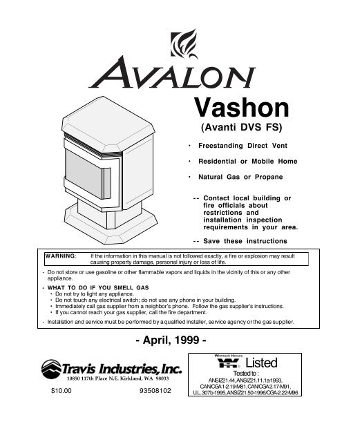
Vashon (Avanti DVS FS) - Avalon
Vashon (Avanti DVS FS) - Avalon
Vashon (Avanti DVS FS) - Avalon

You also want an ePaper? Increase the reach of your titles
YUMPU automatically turns print PDFs into web optimized ePapers that Google loves.
2 Safety Precautions¥ IF YOU SMELL GAS:* Do not light any appliance* Extinguish any open flame* Do not touch any electrical switch or plug or unplug anything* Open windows and vacate building* Call gas supplier from neighborÕs house, if not reached, call fire department¥ This unit must be installed by a qualified installer to prevent the possibility of anexplosion. Your dealer will know the requirements in your area and can inform you ofthose people considered qualified. The room heater should be inspected before useand at least annually by a qualified service person. More frequent cleaning may berequired due to excessive lint from carpeting, bedding material, etc.¥ The instructions in this manual must be strictly adhered to. Do not use makeshiftmethods or compromise in the installation. Improper installation will void the warrantyand safety listing.THIS CONTROLHAS BEENCONVERTED FORNATURAL GASTHIS CONTROLHAS BEENCONVERTED TOLP¥ This heater is either approved for natural gas (NG) orpropane (LP). Burning the incorrect fuel will void thewarranty and safety listing and may cause an extremesafety hazard. Check the label above the gas controlvalve to make sure it matches the fuel being used.Direct questions about the type of fuel used to yourdealer.Ok¥ Contact your local buildingofficials to obtain a permitand information on anyinstallation restrictions orinspection requirements inyour area. Notify yourinsurance company of thisheater as well.¥ If the flame becomes sooty,dark orange in color, orextremely tall, do notoperate the heater. Callyour dealer and arrange forproper servicing.¥ It is imperative that controlcompartments, screens, orcirculating air passagewaysof the heater be kept cleanand free of obstructions.These areas provide the airnecessary for safeoperation.?¥Do not operate the heater ifit is not operating properly inany fashion or if you areuncertain. Call your dealerfor a full explanation of yourheater and what to expect.Gas¥ Do not store or use gasolineor other flammable liquids inthe vicinity of this heater.¥ Keep all furniture or othercombustible items at least36Ó away from the front ofthe heater.¥ Do not operate if any portionof the heater wassubmerged in water or if anycorrosion occurs.Travis Industries 93508102 091002
Safety Precautions 3¥ Do not place clothing orother flammable items on ornear the heater. Becausethis heater can be controlledby a thermostat there is apossibility of the heaterturning on and igniting anyitems placed on or near it.¥ The door (glass) should onlybe opened while lighting thepilot or conducting service.Damaged glass must bereplaced.¥ Any safety screen or guardremoved for servicing mustbe replaced prior tooperating the heater.¥ Operate the heateraccording to the instructionsincluded in this manual.¥ If the main burners do notstart correctly turn the gasoff at the gas control valveand call your dealer forservice. ¥ Light the heater using thebuilt-in piezo igniter. Do notuse matches or any otherexternal device to light yourheater.¥ Never remove, replace,modify or substitute any partof the heater unlessinstructions are given in thismanual. All other work mustbe done by a trainedtechnician. DonÕt modify orreplace orifices.¥ Allow the heater to coolbefore carrying out anymaintenance or cleaning.¥ The pilot flame must contactthe thermopile andthermocouple (see theillustration to the left). If itdoes not, turn the gascontrol valve to ÒOFFÓ andcall your dealer. ¥ This unit is not for use withsolid fuel¥ Do not place anything insidethe firebox (except theincluded fiber logs).¥ If the fiber logs becomedamaged, replace withTravis Industries log set.ThisManual¥ Do not throw this manualaway. This manual hasimportant operating andmaintenance instructionsthat you will need at a latertime. Always follow theinstructions in this manual.¥ Do not touch the hotsurfaces of the heater.Educate all children of thedanger of a hightemperatureheater. Youngchildren should besupervised when they are inthe same room as theheater.¥ Plug the heater into a 120Vgrounded electrical outlet.Do not remove thegrounding plug.¥ DonÕt route the electricalcord in front of, over, orunder the heater¥ Instruct everyone in thehouse how to shut gas off tothe appliance and at the gasmain shutoff valve. The gasmain shutoff valve is usuallynext to the gas meter orpropane tank and requires awrench to shut off.¥ Travis Industries, Inc.grants no warranty,implied or stated, forthe installation ormaintenance of yourheater, and assumesno responsibility of anyconsequentialdamage(s).Travis Industries 93508102 091002
4 Table of ContentsIntroductionIntroduction......................................................1Important Information .........................................1Safety PrecautionsSafety Precautions ............................................2SpecificationsInstallation Options............................................5Features ..........................................................5Heating Specifications........................................5Dimensions.......................................................5Electrical Specifications (for optional blower)...........5Fuel.................................................................5InstallationInstallation Warnings..........................................6Packing List......................................................6Installation Preparation.......................................6Stove Clearances ..............................................6Mobile Home Requirements..................................6Heater Placement Requirements...........................7Floor Protection Requirements..............................7Gas Line Installation...........................................7Gas Inlet Pressure ........................................7Vent Requirements.............................................8Approved Vent Configurations..............................9Restrictor Position.........................................9Elbows........................................................9Measuring Vent Lengths.................................9Vertical TermÕs with (or without) 2 45¡ Elbows ......10Horizontal Terminations..................................11Vertical TermÕs with Two 90¡ Elbows ..................12Horizontal Vent Termination Requirements..............13Vertical Vent Termination Requirements .................13Finalizing the Installation.....................................14Opening the Door...............................................16Log Set and Coal Installation................................17OperationSafety Notice....................................................18Location of Controls ...........................................18Starting the Pilot Flame .......................................19Starting the Heater for the First Time......................20Turning the Heater On and Off ..............................20Adjusting the Flame Height...................................20Adjusting the Blower Speed..................................21Normal Operating Sounds....................................21MaintenanceCleaning Your Heater..........................................22Yearly Service Procedure....................................22Troubleshooting Steps........................................23How this Heater Works........................................24Wiring Diagram ..................................................25Safety LabelSafety Label .....................................................26WarrantyWarranty..........................................................27Optional Equipment & AddendaLP Conversion Instructions..................................28Blower .............................................................32Thermostat.......................................................34Remote Thermostat............................................35Gold Door.........................................................35Gold Grill..........................................................36Firebrick...........................................................36IndexIndex...............................................................38Travis Industries 93508102 091002
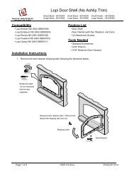
Specifications 5Installation Options:¥ Freestanding Stove¥ Residential or Mobile Home¥ Horizontal or Vertical VentFeatures:¥ Works During Power Outages¥ Realistic ÒWood FireÓ Look¥ Optional Thermostat or Remote Control¥ Variable-Rate Heat Output¥ Optional BlowerHeating Specifications:Approximate Heating Capacity (in square feet)*............500 - 1,500 with Blower, 500 to 1,200 WithoutInput from Low to High (in BTUÕs per hour).................................................15,500 to 31,000Steady State Efficiency............................................................................up to 80%AFUE......................................................................................................70%¥ Heating capacity will vary depending on the homeÕs floor plan, degree of insulation, and the outsidetemperature.** Efficiency rating is a product of thermal efficiency rating determined under continuous operation independentof installed system. To measure the net BTUÕs, multiply the BTU input by the efficiency percentage.Dimensions:The startersection is 1-1/2"above the top. 4-3/4"MeasureClearances tothe Stove Top28-5/8"Weight: 165Lbs.22-1/8"15-5/8"Electrical Specifications (for optional blower)Electrical Rating.........................................................115 Volts, 1.3 Amps, 60 Hz (150 watts on high)Fuel:This heater is shipped in natural gas (NG) configuration but may be converted to propane (LP) usingthe included LP conversion kit. The sticker on top of the gas control valve will verify the correct fuel.Travis Industries 93508102 091002
6 Installation (for qualified installers only)Installation Warnings! Failure to follow all of the requirements may result in property damage, bodily injury, or even death.! This heater must be installed by a qualified installer who has gone through a training program for theinstallation of direct vent gas appliances.! This appliance must be installed in accordance with all local codes, if any; if not, follow current ANSIZ223.1 or NFPA 54 in the USA or the current CGA B149 in Canada.! In Manufactured or Mobile Homes this appliance must be installed to the applicable Mobile HomeStandards: CAN/CSA Z240 MH, the Manufactured Home Construction and Safety Standard, Title 24CFR, Criteria for Manufactured Home Installations, Sites and Communities, and/or ANSI/NFPA 501A.This appliance may be installed in Manufactured Housing only after the home is site located.! This appliance is designed for natural gas or propane (LP). Check the sticker on top of the gas controlvalve.! All exhaust gases must be vented outside the structure of the living-area. Combustion air is drawn fromoutside the living-area structure.! Notify your insurance company before hooking up this appliance.! The requirements below are divided into sections - all requirements must be met simultaneously.Packing List¥ <strong>Vashon</strong> (<strong>Avanti</strong> <strong>DVS</strong> <strong>FS</strong>) ¥ OwnerÕs Manual ¥ Log Set with Embers ¥ Propane Conversion KitInstallation PreparationHINT:HINT:HINT:HINT:Stove ClearancesStraightInstallationsIf converting to LP, convert the appliance prior to installation.Install the logs last - they are fragile.When determining the location of the stove, locate the wall studs (for horizontal penetrations)and ceiling trusses (for vertical penetrations). You may wish to adjust the stove positionslightly to ensure the vent does not intersect with a framing member.Fumes and smoke from the paint curing and oil burning off the steel may occur the first timeyou start this heater. This is normal. We recommend you open windows to vent the room.CornerInstallationsWith this clearance, the ventis 12-7/8Ó from the wall.10"Min.5" Min.With this clearancethe vent is 6-3/8Ó fromthe back wall, 17-7/8Ófrom the side wall.MeasureClearances tothe Stove Top5" Min.MeasureClearances tothe Stove Top45¡Mobile Home Requirements¥ When the stove is installed in a mobile home, it must be bolted to the floor and theappliance grounded (use the optional blower with a grounded circuit or other suitablegrounding method - current ANSI/NFPA 70 or CSA C22.1).Travis Industries 93508102 091002
Installation (for qualified installers only) 7Heater Placement Requirements¥ Heater must be installed on a level surface capable of supporting the heater and vent¥ Due to the high temperature of the heater, it should be located out of traffic and away fromfurniture and draperies. Heater must be placed so no combustibles are within, or canswing within 36Ó of the front of the heater (e.g. drapes, doors)? When placed in a location where the floor to ceiling height is under 7 feet, the installationis considered an alcove and must meet the following requirements:¥ The alcove floor to ceiling height must be at least 58Ó tall¥ The alcove must not be more than 45Ó deep before the ceiling returns to 7Õ¥ The alcove must be at least 42Ó wide¥ The heater must not be placed so the vents below or above the door, along the sides ofheater, or along the back of the heater can become blocked.Floor Protection Requirements¥ When the stove is installed directly on carpeting, vinyl or other combustible material otherthan wood flooring or a high pressure laminate wood floor, the stove must be installed ona metal or wood protection panel extending the full width and depth of the heater(Minimum 22-1/8Ó wide by 15-5/8Ó deep).Gas Line Installation! The gas line must be installed in accordance with all local codes, if any; if not, followcurrent ANSI Z223.1 or NFPA 54 in the USA and the current CGA B149 in Canada.! The heater and gas control valve must be disconnectedfrom the gas supply piping during any pressure testing ofthat system at test pressures in excess of 1/2 psig (3.45kPA). For pressures under 1/2 psig (3.45 kPA), isolatethe gas supply piping by closing the manual shutoffvalve.¥ This heater is designed for natural gas but can beconverted to propane. Check the sticker on the top ofthe gas control valve to verify the correct fuel is used.¥ Leak test all gas line joints and the gas control valve priorto and after starting the heater.¥ The gas inlet accepts a 3/8Ó F.P.T. Fitting¥ The location of the gas inlet is shown below¥ A manual shutoff valve is required for installation (it mustbe located within 3Õ (910 mm) of the heater)Gas Inlet Pressure¥ With the heater off, the inlet pressure must meet therequirements listed in the table below? If the pressure is not sufficient, make sure the piping used is large enough and the totalgas load for the residence does not exceed the amount supplied.? The supply regulator (the regulator that attaches directly to the residence inlet or to thepropane tank) should supply gas at the suggested input pressure listed below. Contactthe local gas supplier if the regulator is at an improper pressure.Standard Input PressureNatural Gas 7Ó W.C. (1.74 Kpa)Propane11Ó W.C. (2.73 Kpa)Travis Industries 93508102 0910025-7/8"3"1/4"
8 Installation (for qualified installers only)Vent Requirements! Always maintain the required 1Ó (25 mm) clearance (air space) to combustible materials to prevent a firehazard. Do not fill air spaces with insulation.! The gas appliance and vent system must be vented directly to the outside of the building, and neverbe attached to a chimney serving a separate solid fuel or gas-burning appliance. Each direct vent gasappliance must use itÕs own separate vent system.Altitude ConsiderationsThis heater has been tested at altitudesranging from sea level to 8,000 feet(2,400 M). In this testing we have foundthat the heater, with its standard orifice,burns correctly with just an air shutteradjustment.! Failure to adjust the air shutter properlymay lead to improper combustion whichcan create a safety hazard. Consult yourdealer or installer if you suspect animproperly adjusted air shutter.¥ When the vent passes through a wall,a wall thimble is required. When thevent passes through a ceiling, asupport box or firestop is required.When the vent passes through theroof, a roof flashing and storm collarare required. Follow the instructionsprovided with the vent (fromDuravent¨) for installing these items.Vertical Termination(Duravent Part # 991)Use a roof flashing and storm collarwhenever passing through the roof(Duravent Part #953 & #943 or #943S)Use a firestop spacer wheneverpassing through a ceiling(Duravent Part #963)8-5/8"(220 mm)8-5/8"(220 mm)Minimum framingfor fire stopMinimumFraming forwall thimbleUse a support boxon exposed ventUse a wall thimblewhenever passingthrough a wall(Duravent Part #942)Maintain a minimum 1" (25 mm)clearance from vent to any combustible(vent is 6 5/8" (170 mm) diameter)Vertical VentRequirementsMaintain a minimum 1"(25 mm) clearance fromvent to any combustible(vent is 6 5/8" (170 mm)diameter)Horizontal VentRequirementsHorizontal Termination(Duravent Part #984)¥ Use Model GS Direct Vent manufactured by Simpson Dura-Vent only (or the Chimney Conversion Kit- see Addendum #2). Follow the installation instructions included with the vent. For the nearestSimpson Dura-Vent supplier, call (800) 835-4429. Part numbers and descriptions are listed below.Straight Lengths908B 6Ó Pipe Length, Black (interior)907B 9Ó Pipe Length, Black (interior)906 12Ó Pipe Length, Galvanized906B 12Ó Pipe Length, Black (interior)904 24Ó Pipe Length, Galvanized904B 24Ó Pipe Length, Black (interior)903 36Ó Pipe Length, Galvanized903B 36Ó Pipe Length, Black (interior)902 48Ó Pipe Length, Galvanized902B 48Ó Pipe Length, Black (interior)911B 11Ó to 14 5/8Ó Pipe, Adjustable, Black (interior)Vent Terminations981 Snorkel Termination (36Ó rise)(for basement installations)982 Snorkel Termination (14Ó rise)(for basement installations)984 Horizontal Square Termination950 Vinyl Siding Standoff991 Vertical TerminationElbows990 90¥ Elbow990B 90¥ Elbow, Black (interior)945 45¡ Elbow945B 45¡ Elbow, Black (interior)¥ Apply high-temperature silicone to the inner and outer pipe beforeassembling the sections (on the male, upper section). This seals theinner pipe from the outer pipe. Slide the sections together and turn 1/4turn until the sections lock in place. Install three metal screws througheach joint to lock the outer section in place (see the instructions includedwith the vent for further details).NOTE: You may screw the first section of vent to the appliance.¥ Horizontal sections require a 1/4Ó rise every 12Ó of travelPenetration, Support Parts942 Wall Thimble940 Optional Wall Thimble Cover941 Cathedral Ceiling Support Box943 Flashing, 0/12 to 6/12 Roof Pitch943S Flashing, 7/12 to 12/12 RoofPitch953 Storm Collar963 Ceiling Firestop988 Wall StrapSiliconeApply a 1/8" (3 mm)bead of hightemperaturesiliconeto the inner andouter pipe. Thesilicone must sealthe inner pipe fromthe outer pipe.Silicone+ Exterior Vent Diameter = 6-5/8Ó , Inner Vent Diameter = 4Ó¥ Horizontal sections require non-combustible support every 36Ó (e.g.: use plumbing tape)Travis Industries 93508102 091002
Installation (for qualified installers only) 9Approved Vent ConfigurationsRestrictor Position¥ A vent restrictor is builtinto the appliance tocontrol the flow rate ofexhaust gases. Thisensures proper flamesfor the wide variety ofvent configurations. Therestrictor consists of abutterfly valve in the airinlet and an adjustmentplate with index holesused to hold the valve ina fixed position.Depending upon thevent configuration, youmay be required to adjustthe restrictor position.The charts for approvedvent configurationsdescribe which positionthe vent restrictor mustbe in.Elbows¥ 2 Elbowmaximum(two 45¡ ortwo 90¡, not one45¡ and one 90¡)MeasuringVent LengthsElbows add 3" to the length ofthe vent system.3"SideView1-1/2"9-5/8"Vent Height iscalculated to thetop of the vent onhorizontalterminations andto the top of thetermination onverticalterminations.To Adjust the Restrictor:1 Determine the correct restrictor position (see the chartsunder "Approved Vent Configurations" - the stockposition is #1). Swing the left access panel open.2 Remove the screw with a 1/4"nutdriver (or screwdriver).3 Rotate the adjustment platecounter-clockwise until the correctindex hole is above the pivot point.Swing the4 Insert the screw into the correctright sideindex hole and tighten.door open.NOTE:Position #1 is thefully open positionIndexHolesScrew2341/4" Nutdriver1AdjustmentPlatePivotPointThe four holes on the restrictorplate correspond to the fourrestrictor positions.This restrictor isin Position #2.Vent Horizontal Run(measure from the closestedge of the starter section tothe end of the termination)12-3/8" tall with1-1/2" of overlapVent sections overlap eachother by 1-1/2"VentHeight8-3/4" wide with 1-1/2"to 3-3/8" of overlapThe startersection is 1-1/2"above the topVent Length(3', 4', etc.)1-1/2"Travis Industries 93508102 091002
10 Installation (for qualified installers only)Approved Venting Configurations for Vertical Terminations with(or without) Two 45¡ Elbows¥ 10Õ Minimum System Height(with or without offsets)0 feet3 feet6' (max)¥ 34Õ Maximum System Height¥ 6Õ Maximum Offset¥ The termination must fall within the shaded areashown in the chart. Use the indicated restrictorposition.¥ If using offsets, use the table below to calculatethe vertical rise and horizontal offsetVerticalRiseOffsetLengthHorizontalOffset34' (max)30 feet25 feet20 feet15 feet10 feetRestrictorPosition # 4NOTE:Restrictor are positionstests. based The upon ideallabrestrictor maypositionespecially vary slightly, when thetermination demarkation is line. near aRestrictorPosition # 3RestrictorPosition # 234' (max)30 feet25 feet20 feet15 feet10 feetOffset Length Hor. Offset Vert. RiseNone 5Ó 1Õ1Õ Section 1Õ 1Õ 7Ó2Õ Section 1Õ 9Ó 2Õ 4Ó5 feetThe maximumoffset lengths istwo 4' sections.5 feet3Õ Section 2Õ 5Ó 3Õ4Õ Section 3Õ 2Ó 3Õ 8Ó4Õ + 1Õ Section 3Õ 9Ó 4Õ 4Ó4Õ + 2Õ Section 4Õ 6Ó 5Õ4Õ + 3Õ Section 5Õ 2Ó 5Õ 9Ó4Õ + 4Õ Section 6Õ 6Õ 9Ó0 feet0 feet3 feet6' (max)0 feetTravis Industries 93508102 091002
Installation (for qualified installers only) 11Approved Venting Configurations with a Horizontal Termination¥ If using a Snorkel Termination (14Ó or 36Ó) add the snorkel height to the vertical height (snorkelterminations are used primarily for basement installations).¥ The termination must fall within the shaded area shown in the chart. Use the indicated restrictorposition.Natural Gas11' (max)5 feet0 feet0 feetPositionRestrictor# 10 feetMin. 1'VerticalSection5 feet5 feet8'(max) 8' (max)11' (max)5 feet0 feetNOTE:Horizontalsectionsrequire a1/4" riseevery 12" oftravel.Propane (LP)11' (max)5 feet0 feet0 feetRestrictorPosition # 10 feetMin. 2'VerticalSection5 feet5 feet8'(max) 8' (max)11' (max)5 feet0 feetNOTE:Horizontalsectionsrequire a1/4" riseevery 12" oftravel.Travis Industries 93508102 091002
12 Installation (for qualified installers only)Approved Venting Configurations for Vertical Terminations withTwo 90¡ Elbows¥ The termination must fall within the shaded area shown in the chart. Use the indicated restrictorposition.0 feet5 feet10 feet16'(max)34' (max)30 feet25 feet20 feet15 feet10 feet(min.)RestrictorPosition # 4NOTE:Restrictor positions arebasedTheupon lab tests.position ideal restrictorslightly, especially may varywhenthedemarkationtermination line.is near aRestrictorPosition # 334' (max)30 feet25 feet20 feet15 feet10 feet(min.)5 feetNOTE:Horizontal sections require a 1/4" (6 mm)rise every 12" (300 mm) of travel.5 feet0 feet0 feet0 feet5 feet(1.5 M)10 feet(3 M)16'(max)(4.9 M)Travis Industries 93508102 091002
Installation (for qualified installers only) 13Horizontal Vent Termination Requirements (see illustration below)ABCDEFGHIJKLMinimum 12Ó (300 mm) clearance from any door or windowMinimum 12Ó (300 mm) above any grade, veranda, porch, deck or balconyMinimum 12Ó (300 mm) from outside corner wallsMinimum 12Ó (300 mm) from inside corner wallsMinimum 12Ó clearance below unventilated soffits or roof surfacesMinimum 18Ó clearance below ventilated soffitsNOTE: Vinyl surfaces require 24ÓMinimum 18Ó (450 mm) clearance below a veranda, porch, deck or balcony (must have two opensides)Minimum 48Ó (1220 mm) clearance from any adjacent buildingMinimum 84Ó (2130 mm) clearance above any grade when adjacent to public walkways or drivewaysNOTE: may not be used over a walkway or driveway shared by an adjacent buildingMinimum 48Ó (1220 mm) clearance from any mechanical air supply inlet, 72Ó (1820 mm) for CanadaMinimum 36Ó (910 mm) clearance above and 48Ó (1220 mm) below and to the sides of non-mechanicalair supply inletMinimum 36Ó (910 mm) from the area above the meter/regulator (vent outlet)Minimum 36Ó (910 mm) from the meter/regulator (vent outlet)EKEAJGFDALCIHBNOTE: Measure clearances to the nearest edge of the exhaust hood.¥ Use the vinyl siding standoff (#950) when installing on an exterior with vinyl siding.¥ Vent termination must not be located where it will become plugged by snow or other material¥ These clearances meet UMC-1994 and the CNA/CGA-B149 code standardsVertical Vent Termination Requirements (see illustration below)Use the verticaltermination (Part #991)Use thechart to theright todeterminethe requiredventterminationheight.RoofPitchHeightRoof PitchFlat to 6/126/12 to 8/128/12 to 9/129/12 to 10/1210/12 to 11/1211/12 to 12/1212/12 to 14/1214/12 to 16/1216/12 to 18/1218/12 to 20/1220/12 or greaterMinimum Height*1' (.3 M)*1.5' (.45 M)*2' (.6 M)2.5' (.75 M)3.25' (1 M)4' (1.2 M)5' (1.5 M6' (1.8 M)7' (2.15 M)7.5' (2.25 M)8' (2.45 M)* In Canada thevent terminationmust be aminimum 2' (.6 M)tall and 2' (.6 M)above any portionof the roof within10' (3 M) of thevent.Travis Industries 93508102 091002
Installation (for qualified installers only) 15! If the vent configuration is installed incorrectly the vent may cause the flames inside the heater to lift orÒghostÓ Ð a dangerous situation. Inspect the flames after installation to insure proper performance. Ifthe vent configuration is correct, yet the flames are lifting or ghosting, shut off gas to the heater andcontact the dealer for information on remedying the problem.Burner PanBurner Ports(consists of slotsand holes)The flames should burn right offthe top of the burner ports (if theyare too blue, adjust the air control).If the flames are lifting, yet thevent configuration is correct,contact your dealer.If the flames are ghosting, yet thevent configuration is correct,contact your dealer.7 Turn the flame adjust knob to its highest position - the flames should be a maximum 9Ó to 10Ó tall.Check the flame on low position. The flames should burn off of each burner hole. If the heater doesnot work correctly, contact your dealer for a remedy.8 Give this manual to the home owner and fully explain the operation of this heater.Travis Industries 93508102 091002
16 Installation (for qualified installers only)Opening the DoorWARNING:The front of the stove becomes very hot during operation.Let the stove cool completely before conducting service.Swing the rightpanel back.Open thelatch.StrikeWith the pawlfree of the strike,the door may beswung open.DoorFramePawlWhen securing the door, makesure the pawl fits over the strikebefore tightening.NOTE: Do not overtighten the pawl by screwingit in. This will permanently damage the latch.Travis Industries 93508102 091002
Installation (for qualified installers only) 17Log Set and Coal InstallationPreparing the Glowing Ember:The glowing ember comes in a small strip. Stretchit as thin as possible (nearly transparent) to form a1-1/2Ó by 7-1/2Ó strip.Approximately 7-1/2Ó by 1-1/2ÓPlace the ember strip over the ledge above thefront burner. Half of the strip should hang over theburner.There may be extra material - save it for future use.Place the log set on thelog/kibble plate.Tuck the front of the ember stripdown, behind the burner with ascrewdriver. Make sure the matof ember wool is not over theburner holes. Tuck it behind theburner tube if necessary.Center the log setand slide it all theway to the rear of thefirebox.Note how only a fewÒwhiskersÓ are over theburner holes.Place the kibbles in front of the firebox.Do not place the kibbles directly over theburner holes.Travis Industries 93508102 091002
18 OperationSafety NoticeRead this entire manual (especially the ÒSafety PrecautionsÓ on pages 2 and 3)before using this stove. Failure to follow the instructions may result in propertydamage, bodily injury, or even death.Location of ControlsON/OF<strong>FS</strong>witchThe on/off switch islocated on theback of the heater.FONO FThe Pilot Flamecan be found belowthe back log.GasControlValveONOTLPIOFFPILOT ADJGas ControlKnobSwing the control coverdown to access the gas controlvalve, igniter, and blower control.VENTHILOFlame AdjustKnobOptional BlowerControlPILOT OFF HIIGNITERLOBLOWERPilot IgniterOn/Off SwitchGas Control KnobFlame Adjust KnobPilot IgniterBlower KnobThis control is used to turn the main burner on and off.This knob is used to control gas to the heater and for starting the pilot.There are three positions, ON, OFF, & PILOT. The pointer directly belowthe knob indicates the position this knob is in.This knob controls the flame height from low (ÒLOÓ) to high (ÒHIÓ). Thepointer to the upper left of the knob points to the position this knob is in.The pilot igniter is used only to start the pilot. When pressed, it sends anelectrical charge to the pilot assembly. This creates a blue spark directlynext to the pilot, igniting the pilot flame.This knob controls the speed of the internal convection blower thatpushes the heated air into the room.? If using a remote control or thermostat, the On/Off Switch must be left ÒONÓ. Turning the On/OffSwitch ÒOFFÓ will keep the heater off always.Travis Industries 93508102 091002
Operation 19Starting The Pilot FlameThe pilot flame is required to ignite the mainburners (it also plays a safety role). It should beleft on once lit. It will stay lit unless the gascontrol valve is turned to "OFF". However, thepilot will go out if the gas is shut off, thepropane tank runs out (or low) or if the stovemalfunctions. If the pilot turns off frequently,call your dealer for information. To start thepilot follow the directions below:aON5 minutesWARNING:When lighting or re-lighting thepilot, the door must be opened (seepage 16).bOTLPIOFFPILOT ADJaOpen the door (see page 16 for details).bcPush the gas control knob in slightly and turnit to the "OFF" position. The knob will notturn from "ON" to "OFF" unless the knob isdepressed slightly. Wait five minutes to letany gas that may have accumulated insidethe firebox escape. If you smell leaking gas,follow the directions on the cover "IF YOUSMELL GAS".Turn the gas control knob to the "PILOT"position and press the knob in, this will allowgas to flow to the pilot light. Press the redbutton on the pilot igniter repeatedly untilyou see the pilot light.cdONL OTONL OTPIPILOT ADJPIPILOT ADJOFFOFFPILOTIGNITER30 secondsWARNING:If the pilot does not light after 15seconds, release the knob and callyour dealer for service. Do notattempt to light pilot until servicehas been performed.eONL OTPIPILOT ADJOFF?NOTE:You may wish to remove the log setto gain a better view of the pilot (seepage 17).d Keep the gas control knob depressed for 30seconds once it is lit.fefRelease the gas control knob. If the pilotgoes out, repeat step C. If the pilot refusesto stay lit, call your dealer for service. Withthe pilot lit, proceed to step ÒfÓ.Close the door.gOFFPIL OTgTurn the gas control knob counter-clockwiseto "ON". The pilot is now lit and the heatercan be turned on and off.ONPILOT ADJTravis Industries 93508102 091002
20 OperationStarting the Heater for the First TimeCleaning Gold SurfacesFingerprints or other marks left on gold surfaces may become etched in place if they are not wipedclean prior to turning the stove on. Clean gold surfaces with denatured alcohol and a soft cloth whenthe heater is cold.Fumes from the Painted Surfaces CuringBurn the heater at a medium setting for approximately one hour the first time. This will cure thepainted surfaces. Fumes from the paint curing and oil burning off the steel may occur. This isnormal. We recommend you open the window to vent the room.CondensationWater may appear on the glass each time you start the heater - this is normal.Blue FlamesThe flames will be blue when first started. After fifteen minutes the flames will turn a more realisticyellow and orange color.Turning the Heater On and OffAfter the pilot has been started...ONOF <strong>FS</strong>ee the instructions includedwith the remote for details onoperation.For systems with thermostats,use this switch to control thetemperature (right is hotter, leftcooler). Some systemsrequire the on/off switch to beon.Use this switch toturn the main burneron and off manually.See the instructionsincluded with theremote for changingthe battery.Warning: Do not place combustible items on top or directly in front of the heater, even temporarily.The optional thermostat may start the heater causing a combustible item to ignite.Note:If the heater turns on and off frequently while using the thermostat, you may want toadjust the flame height down until it produces just enough heat needed.Adjusting the Flame HeightYour heater has an adjustable flame to tailor the look and heat output to your specific needs. It isadjusted by turning the middle dial on the gas control valve.Flame HeightAdjustment KnobIndex MarkVENTHIONVENTHILOOTLPIOFFLOPILOT ADJTurn clockwise to adjust the flame higher, counter-clockwise to lower.Travis Industries 93508102 091002
Adjusting the Blower Speed (optional)Operation 21The blower helps transfer the heat from the heater into the room. It will not turn on until the heater isup to temperature (approximately 10 minutes after starting). See the illustration below for instructionson adjusting the blower speed.PILOTIGNITEROFF HILOBLOWERBlower KnobTurn the knob all the way counter-clockwise to turnthe blower off. One click clockwise turns theblower to high speed. Turning the knob clockwisefrom the high position decreases the speed of theblower.Normal Operating SoundsBlowerThis heater uses a blower topush heated air into theroom. You will hear thesound of air movement thatincreases as the speed isincreased.Pilot FlameThe pilot flame,which remains on,makes a very slight"whisper" sound.The appliance maycreak with changeof temperature.THIS IS NORMAL.Gas Control ValveAs the gas control valve is turnedon and off you will hear a dullclicking sound. This is the valvei d h i dBlower Snap DiskThis part canproduce a clickingsound as it turns theblower on and off.Travis Industries 93508102 091002
22 MaintenanceCleaning Your HeaterWarning Fingerprints or other marks left on the optional gold surface may become etched in placeif they are not wiped clean prior to turning the stove on.With the heater cool, use denatured alcohol and a soft cloth to clean gold surfaces. Other cleanersmay leave a film that may become etched into the gold.Yearly Service ProcedureWarning Failure to inspect and maintain the heater may lead to improper combustion and apotentially dangerous situation. We recommend the following procedures be done by aqualified technician.1 Check the pilot flame. It should engulf approximately 3/8Ó of the top of the thermocouple(see illustration below). If it does not, contact your dealer for service.2 Shut off gas to the heater by turning the gas control knob to ÒOFFÓ (see step A underÒStarting the PilotÓ on page 19). Let the heater cool for 15 minutes. Open the door (seepage 16).3 Remove the log set and embers (see page 17 - NOTE: the log set is fragile). If anylog is cracked or deteriorated, replace it when re-installing. Check the logs for sooting. Ifexcessive sooting is found, the heater will require adjustment. Contact your dealer.4 Clean the burner pan (especially in the burner holes and slots) and inspect the following:¥ Check for burner pan holes that are cracked, severely warped, or corroded.¥ Check the firebox and area around the pilot to make sure there is no warping ordamage.If any problem is found, discontinue use and contact your dealer for service.Check the walls andceiling of the firebox fordeterioration.Before Disassembly: Check the pilotflame. It should impinge the top 3/8Ó of thethermopile and engulf the thermocouple.BurnerPanCheck theburner holesThermopilePilot Hood3/8ÓThermocouple5 Replace the log set. Inspect the glass gasket. If it is deteriorated, replace. It may be reattachedto the glass using high-temperature gasket cement. If the glass is damaged,replace it.6 Check the gas control valve and all of the gas lines. If any damage is found, discontinueuse and contact your dealer for service.Travis Industries 93508102 091002
Maintenance 237 To check the door seal, place a dollar bill along the door perimeter then close and latchthe door. If the dollar bill is held in place securely, the door seal is adequate. However, itthe dollar bill slides out easily, you should adjust the door. Contact your dealer to obtaindirections on tightening the door seal.8 Start the pilot and turn on the main burner. The flames should be orange/yellow and nottouch the top of the firebox. If the pilot or main burners do not burn correctly, contact yourdealer for service. Monitor the blower operation.9 Remove any debris or vegetation near the vent termination. Contact your dealer if anysooting or deterioration is found near the vent termination.Troubleshooting StepsProblem: Possible Cause: Remedy:Pilot Will Not FlameMain Burners Will NotStartRemote Control DoesNot WorkThermostat Does NotWorkBlower Does NotOperateA gas shut off valve is turned off......................The gas control knob isnÕt turned to ÒPILOTÓ.......The valve control knob isnÕt pushed in ...............The igniter wasnÕt pressed repeatedly ...............No spark from igniter......................................The pilot flame has gone out............................The gas control valve is turned to ÒPILOTÓ or ÒOFFÓThe ON/OFF switch is turned to ÒOFFÓ ...............The remote control is not working correctly.........The thermostat is disconnected or set too high ...The pilot light has gone out..............................The gas control valve is turned to ÒPILOTÓ or ÒOFFÓThe ON/OFF switch is turned to ÒOFFÓ ...............The remote is too far away from the heater .........The remote control receiver is turned ÒOFFÓ........One of the two remote control batteries is dead...The pilot flame has gone out............................The gas control valve is turned to ÒPILOTÓ or ÒOFFÓThe ON/OFF switch is turned to ÒOFFÓ ...............The thermostat is set too high..........................Make sure blower control is turned ÒONÓThe heater is not getting electricity ...................The heater is not up to temperature...................Check all gas shut off valvesSee ÒStarting the Pilot FlameÓ Pg 19See ÒStarting the Pilot FlameÓ Pg 19See ÒStarting the Pilot FlameÓ Pg 19Igniter Faulty - Contact your DealerSee ÒStarting the Pilot FlameÓ Pg 19See ÒStarting the Pilot FlameÓ Pg 19Turn the ON/OFF switch to ÒONÓReplace the batteriesSet the thermostat to a lowertemperatureSee ÒStarting the Pilot FlameÓ Pg 19See ÒStarting the Pilot FlameÓ Pg 19Turn the ON/OFF switch to ÒONÓUse the remote closer to the heaterSee the remote control instructionsSee the remote control instructionsSee ÒStarting the Pilot FlameÓ Pg 19See ÒStarting the Pilot FlameÓ Pg 19Turn the ON/OFF switch to ÒONÓSet the thermostat to a lowertemperatureSee ÒAdjusting Blower SpeedÓ Pg. 21Make sure it is plugged in and theoutlet is providing electricitySee ÒOperating Your HeaterÓFlames Are Too Blue The heater has just been started...................... This is normal - see ÒStarting theHeater for the First TimeÓFlames Are Too Short(Under 6Ó)The flame height may be turned too low.............. Turn the flame height to ÒHIÓ -See ÒAdjusting the Flame HeightÓTravis Industries 93508102 091002
PIPILOT ADJP IPILOT ADJ24 MaintenanceHow this Heater WorksWarningThis heater was designed with safety as the primary concern. Many of the componentsinside this heater are for safety purposes. Therefore, only certified gas servicetechnicians should service this heater.What Turns the Main Burners On and OffThis heater uses a millivolt system to control its operation (a millivolt is a very small amount ofelectricity). The thermopile and thermocouple generate electricity when heated by the pilot flame.This electricity is used to operate the gas valve. Without enough electricity, the gas valve will not turnon. That is why when starting the pilot the gas control knob has to be pressed in long enough for thethermocouple to heat up and generate enough electricity. The thermopile provides power for theON/OFF switch, remote control, or thermostat (see the illustration below). Because the thermopilegenerates the electricity needed to turn the heater on and off, this heater can be operated when thepower is out (although the blower will not run).When heated, the thermopilegenerates electricity (a very smallamount, measured in "Millivolts").This electricity isused to operate themain burners.ONL OTOFFVENTHILOThe main burnersare switched on andoff using theelectricity generatedby the thermopile.The ON/OFF switch,remote control, orthermostat controlthe circuit to the mainburner.MAIN BURNERONOFFWhat Prevents Gas Buildup¥ This appliance utilizes a high-technology gas valve in conjunction with a pilot flame to ensure no gasbuilds up inside the firebox.¥ The thermocouple (next to the pilot) senses when the pilot flame is lit. If the pilot flame goes out, thisthermocouple no longer generates electricity, causing the gas valve to automatically shut off all gas tothe heater, preventing the pilot or burner from spilling gas into the firebox.Pilot FlameThe pilot flame is a time-provencomponent that eliminates the possibilityof gas buildup inside the firebox.Gas ValveThis high-technology valve automaticallyshuts off all gas if it does not receive a signalfrom the thermocouple. If any component isdamged or sensing a malfunction, or if thewiring is damaged, it will shut off all gas.ONO TLOFFHILOVENTExternal Shut Off ValveThis valve is placed on the gas lineto shut off gas to the applianceduring maintenance procedures.ThermocoupleThe thermocouple generates a smallamount of electricity. If the pilot flamegoes out, the gas valve automaticallyshuts off all gas.Ceramic GlassThe glass in your heater is the mostdurable glass available. It has beentested to be extremely resistant tobreakage and temperature changes.Travis Industries 93508102 091002
Maintenance 25Wiring DiagramThermopilePiezo IgniterBrownEPUterminalGas Control ValveRedWhiteOrangeThermocoupleRedCopper Co-Axial WireJumper Wire(ManualOperation)GreenOn/OffSwitchBlowerMotorChassisGroundGreenOptionalThermostatOptionalRemoteControlBlackBlackBlackWhiteWhiteWhiteBlack120 VoltGrounded A.C.Power SupplyBlowerThermodiskBlowerRheostatBlack120 V.BlowerCircuitReplacement Parts:Blower, Convection 98900755A Orifice, Gas, .0625, LP 98900717Blower Rheostat w/ Off Position 98900758 Orifice, Gas, #37, NGr 98900713Control Valve, Gas, Direct Vent, LP 97300130 Orifice, Pilot, .016 91001506Control Valve, Gas, Direct Vent, NG 97300120 Orifice, Pilot, .021 91001505Conversion Parts, LP 98900743 Piezo Igniter 98900751Conversion Parts, NG 93005100 Pilot Assembly, Top Conversion 93006021Pilot Tube 91001508Gasket, Door, 7/8Ó, Black 99900402 Power Cord, With Molex Connector 99300656Glass, Front 93006042 Pressure Relief Doors 91001542Glass Gasket, Flat, Self-Adhesive 99900404 Regulator, Natural Gas 98900733Glass, Side (one piece) 93006043 Regulator, Propane (LP) 98900734Glowing Ember Strip ( Shredded Metal Alloy) 93006052 Snap Disk, 120 Degree - 2 Prong 98900720Knob, for Rheostat 99300657 Switch, On/Off 98900747Log, Ember Coals 97200334 Thermocouple 98900748Log Set ( One Piece) 93006051 Thermopile 98900752Manual 93508102 Wiring Harness 97200307Travis Industries 93508102 091002
26 Safety LabelThe listing label is shown below for your records. It can be found on the back panel.Tested &Listed byRTM<strong>Avanti</strong> <strong>DVS</strong> <strong>FS</strong>Listed Gas-FiredDirect Vent Wall FurnaceCertified for USA & CanadaTested to: ANSI Z21.44-1995 Gas-Fired Gravity and Fan type Direct-Vent Wall Furnace, and applicable sections of ANSI Z21.11.1a-1993 Gas-FiredVented Room Heaters. CAN 1-2.19-M81 Gas-Fired Direct-Vent Wall Furnace, CAN/CGA 2.17-M91 “Gas-Fired Appliances for use at High Altitudes”,UL307b-1995 “Gas Burning Heating Appliances for Manufactured Homes”, and ANSI Z21.50-1996/CGA-2.22-M96 Vented Gas Fireplaces.Must be installed in accordance with the manufacturer’s installation instructions and all local codes, if any; if not, follow current ANSI Z223.1,NFPA 54 and CGA B149. In Manufactured or Mobile Homes this appliance must be installed to the applicable Mobile Home Standards: CAN/CSAZ240 MH, the Manufactured Home Construction and Safety Standard, Title 24 CFR, Criteria for Manufactured Home Installations, Sites andCommunities, and/or ANSI/NFPA 501A. This appliance is designed to operate on natural gas, or propane (LP). This appliance uses a millivolt-typecontrol system consisting of a gas control valve/regulator, a standing pilot burner assembly, a thermopile, a piezo ignitor, and the ON/OFF switch.THIS UNIT DOES NOT REQUIRE 110 VOLT POWER TO OPERATE. All exhaust gases must be vented outside the structure of the living-area.Combustion air is drawn from outside the living-area structure. This appliance may be installed in Manufactured Housing only after the home issite located. May be installed in a bedroom - in Canada install with a listed thermostat, in the USA install per local codes.WARNINGS:Improper installation, adjustment, alteration, service or maintenance can cause injury or property damage. Refer to the information in theowner’s and installation manual provided with this appliance. For assistance or additional information consult a qualified installer, serviceagency or the gas supplier.Installation and repair should be performed by a qualified service person. The appliance should be inspected before use and at least annuallyby a qualified service person. More frequent cleaning may be required where excessive lint from material like carpeting and bedding is present.The control compartment, the burner compartment and all circulating air passageways of the appliance must be kept clean and clear at alltimes.Due to high temperatures, the appliance should be located out of traffic and away from furniture and draperiesThis appliance must not be connected to a chimney flue servicing a separate solid fuel burning appliance.This room heater is a Direct-Vent Gas-Fired appliance. DO NOT burn wood or other material in this heater.Children and adults should be alerted to the hazards of high surface temperature and should stay away to avoid flesh burns or clothing ignition.Young children should be carefully supervised at all times when they are in the same room as the appliance.CAUTION:All safety screen or guard components removed for servicing, must be replaced prior to operating the appliance.Clothing or other flammable material and liquids with flammable vapors should not be placed on or near the appliance.Risk of electrical shock. Switch the household breaker off or remove fuse before servicing unit.Use Simpson DURA-VENT direct vent system (Model GS) to vent this appliance to the exterior (direct discharge only without duct connection).Minimum Clearances to CombustiblesUnit to Sidewall ................................... 10” Alcove Min. Height....................................... 58”Unit to Backwall .................................. 5” Alcove Max. Depth ....................................... 45”Unit to Cornerwall............................... 5” Alcove Min Width ......................................... 42”Front of Unit ........................................ 36”L.P. N.G. L.P. N.G.Input Rate on “HI” (BTU/Hr)* . . . . . . 31,000 31,000 Minimum Inlet Pressure (inches W.C.) . . . . . . . . 11” 5.5”Input Rate on “LO” (BTU/Hr)* . . . . . 15,500 15,500 Maximum Inlet Pressure (inches W.C.) . . . . . . . . 13” 7”Main Burner Orifice (DMS)* . . . . . . . .0625 #37 Manifold Pressure on “HI” (inches W.C.) . . . . . . 10” 3.5”Output (BTU/Hr) Fan On* . . . . . . . . . 25,575 24,800 Manifold Pressure on “LO” (inches W.C.) . . . . . 2.7” 1”Output (BTU/Hr) Fan Off* . . . . . . . . . 25,265 24,645This room heater is equipped at the factory for use with natural gas. If conversion to propane (LP) fuel is desired theoptional factory conversion kit must be used.Blower Electrical Rating: 115v, 1.5 Amps, 60 Hz FAN TYPE VENTED CIRCULATORManufacture 1998 Jan. Apr. Jul. Oct.Date: 1999 Feb. May Aug. Nov.2000 Mar. Jun. Sep. Dec.10850 117th Pl. N.E. Kirkland, WA 98033IGNTravis Industries 93508102 091002
Warranty 27To register your TRAVIS INDUSTRIES, INC. 7 Year Warranty, complete the enclosed warranty card and mail it within ten (10) days of the appliancepurchase date to: TRAVIS INDUSTRIES, INC., 10850 117th Place N.E., Kirkland, Washington 98033. TRAVIS INDUSTRIES, INC. warrants this gasappliance (appliance is defined as the equipment manufactured by Travis Industries, Inc.) to be defect-free in material and workmanship to the originalpurchaser from the date of purchase as follows:Years 1 & 2 - COVERAGE: PARTS & LABORBurner Assembly:Burner, Burner Pan, Air Shutter Assembly, Main BurnerOrificeFirebox Assembly:Adjustable Air Restrictor, Pressure Relief Mechanisms(direct vents only), Glass Attachment MechanismGas Control AssemblyAdjustable control valve, millivolt wiring and connectors(located within the metal heater structure), thermopile,thermocouple, pilot hood, orifices, pilot gas line, piezoignitorCeramic GlassGlass (breakage from thermal shock)Ceramic LogsLog Set, Coals, Ember Strip (Steel Fiber)Optional Brass DoorSolid Brass Door (see ÒConditions and ExclusionsÓ # 9)Gold PlatingGold or Nickel Door, Optional Grill (see ÒConditions and ExclusionsÓ # 9)Electrical Assembly :Blower, wiring harness, snap discs, rheostat speed controlExclusions: Paint, GasketingYears 3 THROUGH 5 - COVERAGE: PARTS & LABORBurner Assembly:Burner, Burner Pan, Air Shutter Assembly, Main BurnerOrificeOptional Brass DoorSolid Brass Door (see ÒConditions and ExclusionsÓ # 9)Exclusions:Firebox Assembly:Adjustable Air Restrictor, Pressure Relief Mechanisms(direct vents only), Glass Attachment MechanismAccessoriesLegs, Pedestal, Panels, Cast Firebacks, Shell AssemblyConvection Heat ExchangerRe-Installation AllowanceIn cases where heater must be removed from home forrepairs, a partial cost of re-installation is covered (preauthorizationrequired)One-Way Freight AllowanceOne-way freight allowance on pre-authorized repair done atfactory is covered.Convection Heat ExchangerOne-Way Freight AllowanceOne-way freight allowance on pre-authorized repair done atfactory is covered.Paint, Gasketing, Electrical Assembly, Gas Control Assembly, Ceramic Glass, Ceramic Logs, Gold & Nickel Plating, Accessories,Re-Installation AllowanceYears 6 & 7 - COVERAGE: PARTS ONLYBurner Assembly:Burner, Burner Pan, Air Shutter Assembly,Main Burner OrificeExclusions:Firebox Assembly:Adjustable Air Restrictor, Pressure Relief MechanismsOptional Brass Door(direct vents only), Glass Attachment MechanismSolid Brass Door (see ÒConditions and ExclusionsÓ # 9)Paint, Gasketing, Electrical Assembly, Gas Control Assembly, Ceramic Glass, Ceramic Logs, Gold & Nickel Plating, Accessories,Convection Heat Exchanger, Re-Installation Allowance, One-Way Freight Allowance, LaborCONDITIONS & EXCLUSIONS1. This new gas appliance must be installed by a qualified gas appliance technician. It must be installed, operated, and maintained at all times in accordance with the instructions inthe OwnerÕs Manual. Any alteration, willful abuse, accident, neglect, or misuse of the product shall nullify this warranty.2. This warranty is nontransferable, and is made to the ORIGINAL purchaser, provided that the purchase was made through an authorized TRAVIS dealer.3. Discoloration and some minor expansion, contraction, or movement of certain parts and resulting noise, is normal and not a defect and, therefore, not covered under warranty.The installer must ensure the appliance is burning as per the rating tag at the time of installation. Over-firing (operation a bove the listed BTU rate) of this appliance can causeserious damage and will nullify this warranty.4. The warranty, as outlined within this document, does not apply to the chimney components or other Non-Travis accessories used in conjunction with the installation of this product.If in doubt as to the extent of this warranty, contact your authorized TRAVIS retailer before installation.5. Travis Industries will not be responsible for inadequate performance caused by environmental conditions such as nearby trees, buildings, roof tops, wind, hills or mountains ornegative pressure or other influences from mechanical systems such as furnaces, fans, clothes dryers, etc.6. This Warranty is void if:a. The unit has been operated in atmospheres contaminated by chlorine, fluorine or other damaging chemicals.b. The unit is subject to submersion in water or prolonged periods of dampness or condensation.c. Any damage to the unit, combustion chamber, heat exchanger or other components due to water, or weather damage which is the result of, but not limited to, improperchimney/venting installation.7. Exclusions to this 7 Year Warranty include: injury, loss of use, damage, failure to function due to accident, negligence, misuse, improper installation, alteration or adjustment ofthe manufacturer's settings of components, lack of proper and regular maintenance, damage incurred while the appliance is in transit, alteration, or act of God.8. This 7 Year warranty excludes damage caused by normal wear and tear, such as paint discoloration or chipping, worn or torn gasketing, corroded or cracked logs, embers, etc.Also excluded is damage to the unit caused by abuse, improper installation, modification of the unit, drilling of the orifices, or the use of fuel other than that for which the unit isconfigured. Units are shipped for natural gas and must be converted to propane using the included conversion kit. Confirm fuel configuration with your installer.9. Damage to gold, nickel, or brass surfaces caused by fingerprints, scratches, melted items, or other external sources left on the surface is not covered in this warranty. Damagefrom the use of cleaners other than denatured alcohol on gold or nickel is not covered in this warranty. Damage from the use of abrasive cleaners on brass is not covered in thiswarranty.10. TRAVIS INDUSTRIES, INC. is free of liability for any damages caused by the appliance, as well as inconvenience expenses and materials. Incidental or consequential damagesare not covered by this warranty. In some states, the exclusion of incidental or consequential damage may not apply.11. This warranty does not cover any loss or damage incurred by the use or removal of any component or apparatus to or from the gas appliance without the express writtenpermission of TRAVIS INDUSTRIES, INC. and bearing a TRAVIS INDUSTRIES, INC. label of approval.12. Any statement or representation of TRAVIS products and their performance contained in TRAVIS advertising, packaging literature, or printed material is not part of this 7 yearwarranty.13. This warranty is automatically voided if the applianceÕs serial number has been removed or altered in any way. If the appliance is used for commercial purposes, it is excluded fromthis warranty.14. No dealer, distributor, or similar person has the authority to represent or warrant TRAVIS products beyond the terms contained within this warranty. TRAVIS INDUSTRIES, INC.assumes no liability for such warranties or representations.15. Travis Industries will not cover the cost of the removal or re-installation of hearths, facing, mantels, venting or other components.16. If for any reason any section of this warranty is declared invalid, the balance of the warranty remains in effect and all other clauses shall remain in effect.17. THIS 7 YEAR WARRANTY IS THE ONLY WARRANTY SUPPLIED BY TRAVIS INDUSTRIES, INC., THE MANUFACTURER OF THE APPLIANCE. ALL OTHERWARRANTIES, WHETHER EXPRESS OR IMPLIED, ARE HEREBY EXPRESSLY DISCLAIMED AND PURCHASERÕS RECOURSE IS EXPRESSLY LIMITED TO THEWARRANTIES SET FORTH HEREIN.IF WARRANTY SERVICE IS NEEDED:1. If you discover a problem that you believe is covered by this warranty, you MUST REPORT it to your TRAVIS dealer WITHIN 30 DAYS, giving them proof of purchase, thepurchase date, and the model name and serial number.2. Travis Industries has the option of either repairing or replacing the defective component.3. If your dealer is unable to repair your applianceÕs defect, he may process a warranty claim through TRAVIS INDUSTRIES, INC., including the name of the dealership where youpurchased the appliance, a copy of your receipt showing the date of the applianceÕs purchase, and the serial number on your appliance. At that time, you may be asked to shipyour appliance, freight charges prepaid, to TRAVIS INDUSTRIES, INC. TRAVIS INDUSTRIES, INC., at its option, will repair or replace, free of charge, your TRAVIS applianceif it is found to be defective in material or workmanship within the time frame stated within this 7 year warranty. TRAVIS INDUSTRIES, INC. will return your appliance, freightcharges (years 1 to 5) prepaid by TRAVIS INDUSTRIES, INC., to your regional distributor, or dealership.4. Check with your dealer in advance for any costs to you, when arranging a warranty call. Dealers may require you to pay a service or trip charges for any warranty work. Thischarge can vary from store to store.Travis Industries 93508102 091002
28 Optional EquipmentLP Conversion InstructionsThe propane conversion kit should be installed prior to installing gas line to ensure proper gas use.1 Open the door (see page 16).2 Remove the burner (see illustration below).1/4" NutdriverRemove the four screws holding the log/ember plate in place.Remove the screw holdingthe burner pan in place.1/4" NutdriverRotate the burner upNOTE:When replacing the burner,make sure the burner insertsall the way up against theorifice shoulder.AirControlSliderSlide the burner to theright until the burnerdisengages from theair control slider.OrificeBurnerOrificeShoulderTravis Industries 93508102 091002
Optional Equipment 293 Follow the directions below to replace the natural gas orifice with the propane (LP) orifice.When replacing the burner pan (step # 7), make sure to guide the air control shutter overthe burner pan.aLoosen the air shuttercontrol (see page 14).OrificebRotate the air control shutteraway from the orifice.AirControlShuttercUse a 1/2Ó open end wrenchto unscrew the orifice.5/16Ó1/2" WrenchNOTE:Screw the LPorifice in so theorifice shoulderprotrudes 5/16Ó(indicating fullinsertion)..062537dThe new LP orifice hasÒ.0625Ó stamped on it.Apply threadsealant to thenew orificeprior toinstallation.The old NGorifice has Ò37Óstamped on it.Travis Industries 93508102 091002
30 Optional Equipment4 Remove the pilot orifice following the instructions below. Replace with the propane pilot orifice. Thepropane conversion kit includes a .016Ó (labeled LP 16) or .011Ó (labeled LP 11) pilot orifice. The.016Ó orifice is preferred because it allows for greater pilot adjustment.Remove the pilothood assembly byunscrewing the twoattachment screws.Pull the pilot orificeretainer and pilot orificeupwards to remove.Pilot HoodAssemblyPilot OrificeRetainerPilot OrificeOrifice Identification:LP (Propane) OrificesLL1 11 6PPPhillipsScrewdriver(preferred)NG (Natural Gas) Orifices1 8N2 1N(preferred)5 Remove the pilot orifice. It may be resting on the pilot tube or lodged inside the pilot assembly (tapthe assembly from above until it falls out). Place the propane pilot orifice onto the pilot tube (the LPorifice is .016Ó diameter - it has Ò16Ó stamped on it). Insert the pilot tube (with orifice) into the pilot tubeport and tighten the compression nut until tight. NOTE: Leak test this connection after the heater isinstalled and gas is connected.6 Replace the pilot assembly (follow the instructions in step 4 in reverse order). Make sure the pilotassembly gasket is placed correctly.7 Replace the burner pan (see step 3). Install the logs and embers. Close the door.Travis Industries 93508102 091002
Optional Equipment 318 Remove the regulator from the front of the gas control valve. Replace with the propane regulator,using the new gasket and screws included with the regulator. NOTE: Leak test this area after theheater is installed, gas is connected, and the main burner is lit.Align the regulatorgasket so it is flatand the two tabs fitthrough the twoholes on thegasket.NOTE: These holes stripeasily. Use a handscrewdriver and tighteneach screw evenly.VENTHILOThese screws hold theregulator in place.NOTE: use the newscrews included withthe regulator.VENTHIONPhillipsScrewdriverLOOTLPIOFFPILOT ADJRegulator GasketNOTE: use the new gasketincluded with the regulator.LP (propane) regulators have a11.0 2.7 stamped here.9 Place the included propane label over the natural gaslabel on top of the gas control valve.10 Make the gas line connection, start the heater andthoroughly leak-test all gas connections and theregulator. Check the pilot. Adjust if necessary.THIS CONTROLHAS BEENCONVERTED TO LP3/8ÓONThermocoupleThermopileOTLPILOT ADJCover Screw GasketPIOFFNeedle ValveMicro (1/16Ó)StandardScrewdriverCover ScrewPilot HoodStandardScrewdriverBlower (Part # 98900127)The optional blower boosts airflow through the convection channel, increasing heat transfer. Followthe directions below to install.Hint We strongly suggest installing the blower prior to installing the stove. It can beinstalled after installation, but it is more difficult.4 Remove the control cover from the front of the stove (see the directions to the right).Remove the four screwsholding the control panelin place.ControlPanel1/4" NutdriverLay the control panel facedown so the area behind itmay be accessed.Travis Industries 93508102 091002
32 Optional Equipment2 Attach the rheostat and rheostat wires following the directions below.Remove Attach with the the included rheostat nut.to the control panela it loose with the a button screwdriver.plug by pryingb cPILOTIGNITERAttach the blower stickerto the control panel (makesure it is centered overthe large hole).PILOTIGNITERNOTE: this tab fits into thehole on the mountingbracket.PILOTIGNITERConnect the wires labeledÒRheostat WiresÓ from the stoveto the wires on the rheostat(orientation does not matter).OFFOFF HIOFFLOHILOLOHIBLOWER11/16" WrenchBLOWERAttach the knob.BLOWER3 Install the snap disk following the directions .Snap Disk Bracket(attached to stove)Snap DiskControlPanelSnap DiskWiresSlide the snap disk into the snapdisk bracket. Attach the blackand white snap disk wires to thesnap disk (orientation does notmatter). Use a lock tie to securethe wire away from the burnerpan to prevent burning.4 Install the blower mounting hardware onto the left and right fan mounting bracket.a Install the grommets (with spacersb Insert the brackets ontoinserted inside), and washers onto onethe blower assembly.bracket. Attach the nuts to secure.The slots on the blowerRepeat for the opposite side.assembly slide into thegaps in the rubbergrommets.Top ViewBlowerBracketRubberGrommetNutSpacerWasher11/32" NutdriverBlower AssemblyTravis Industries 93508102 091002
Optional Equipment 335 Use the included strain relief to attach the power cord to the left side mounting bracket.aInsert the molexconnector through theleft side fan mountingbracket.bUse pliers to compress the strainrelief from the top and bottom whilepushing it into the hole in thebracket.6 Install the blower assembly following the directions below.5/16" NutdriverbAttach the powercord to the wiringharness.aSlide the blower intoplace. The notches onthe mounting bracketshang on screws in thepedestal. Secure withthe four screws.5/16" Nutdriver dUse lock ties to secure any excess wireaway from the burner pan and blower.cAttach the wiring harness to the blower(orientation does not matter).7 Attach the fan guard with the six screws following the directions below.1/4" NutdriverAttach the fanguard with the sixsmaller (#8)screws. You maywish to pre-threadthe holes in the fanguard and base ofthe stove to easeinstallation.8 Replace the control panel removed in step 1.Travis Industries 93508102 091002
34 Optional EquipmentThermostat (Part # 99300650)! Do not connect 120 VAC to the gas control valve or wiring of this unit.1 Route the thermostat wire through the back of the right side panel (there is a hole beneath the on/offswitch) and attach to the on/off switch (see the illustration below).Back of on/off switchcRemove the greenjumper wire.aOpen the rightside panel.Back ofon/offswitchbRoute thewire behindthe panel tothe on/offswitch.dAttach the quick connectsfrom the wire to the two postson the on/off switch(orientation does not matter).2 Pull through all the slack on the wire (you may wish to wrap the wire in electrical tape to preventdamage to the wire). Determine a location for the thermostat that is within range of the 50Õ length ofthermostat wire. It should be centralized in the room and away from the heater. The wire may berouted externally on the wall or behind the wall (preferred).3 Cut the thermostat wire so there is approximately 6" of slack (NOTE: Do not splice thermostat wirestogetherÐthis leads to too much electrical resistance). Follow the directions below to install thethermostat.aPull the cover off the thermostat50 60 70 80 90Robertshaw50 60 70 80 90bRun the thermostat wiresthrough the wall (cut off excesswire, leaving 6Ó of slack).dAttach the thermostat tothe wall through thesetwo holes.cExpose 1/2Ó of wire andattach to these two posts.eRe-attach the coverremoved in step ÒaÓ.StandardScrewdriverTravis Industries 93508102 091002
Remote ThermostatOptional Equipment 35! Do not connect 110-120 VAC to the gas control valve or wiring system of this unit.¥ Follow the instructions included with the remote thermostat for installation.Using the Remote ThermostatThe remote thermostat has a 1 to 2 minute lag time between the time the thermostat is turned up andthe heater turns on. Included with the remote thermostat is a set of instructions that details theoperating characteristics of this optional component.Gold Door (part # 99300523)Follow the directions below to install the optional gold door.Remove the black door by slidingit up and off the door frame.Slide the gold door onto the doorframe.HINT: align the bottom joggleclips over the brackets on thedoor and slide into place. Thenlift up slightly on the door toattach the upper clips.The door is held in place witheight joggle clips.DoorDoor FrameWARNING:Clean the gold surface prior to starting the stove. Any marks left on the gold may become etched-inby the heat of the stove. Use denatured alcohol and a soft cloth to clean.Soft ClothDenaturedAlcoholTravis Industries 93508102 091002
36 Optional EquipmentGold Grill (part # 93005034)Follow the directions below to install the optional gold grill.abSwing the door openRemove the blackgrill, with mountingplate, from thestove.cdRemove the mounting platefrom the black grill and attach itto the gold grill.Attach the gold grill to the stovewith the screws removed instep ÒbÓ.MountingPlate1/4" Nutdriver1/4" NutdriverFirebrick (part # 98500746)Follow the directions below to install the optional firebrick.aSwing the door openScrew(includedon stove)Firebrick ClipSideFirebricks5/16" Nutdriver5/16" NutdriverRearFirebrickbcdefRemove the log set (see page 17)Remove the two screws in theroof of the firebox near the front.Place the rear firebrick against the back wall ofthe firebox. The side firebricks, once installed,will hold the rear firebrick in place.Place the left side firebrick into place. Align oneof the firebrick clips (included with the firebrickkit) over the left side hole exposed in step ÒcÓ.Attach the clip with the screw removed in stepÒcÓ.Repeat step ÒeÓ for the right sidefirebrick.Travis Industries 93508102 091002
Optional Equipment 37Travis Industries 93508102 091002
38 IndexAdjusting the Blower Speed........................21Adjusting the Flame Height .........................20AFUE.........................................................5Air Shutter Adjustment................................14Alcoves......................................................7Altitude Considerations...............................8Amperage (of blower)..................................5Blower Speed ............................................21BTU Output................................................5Burn Rate...................................................5Burner Installation.......................................28Cap (vent termination).................................13Cleaning Your Heater..................................22Clearances.................................................6Condensation ............................................20Controls.....................................................18Dimensions................................................5Door Opening ............................................16Efficiency...................................................5Elbows.......................................................9Electrical Specifications...............................5Emissions ..................................................5Flame Height..............................................20Floor Protection Requirements....................7Fuel...........................................................5Fumes (if you smell gas See Inst. on Cover)..20Gas Control Valve (Location)........................18Gas Inlet Installation ....................................7Gas Leak...............................See Inst. on CoverGas Line Connection ..................................7Gas Smell..............................See Inst. on CoverHeating Capacity.........................................5High Wind Vertical Terminations...................13Horizontal Vent Termination Requirements ..13How to Measure Vent Lengths ....................9Installation Options .....................................5Installation Preparation................................6Leaking Gas .......................See Inst. on CoverLifting Flames.............................................15Listing Label (Safety Label) .........................26Log Installation ...........................................17Maintaining Your StoveÕs Appearance..........22Natural Gas Verses Propane........................2On/Off Operation........................................20On/Off Switch (Location).............................18Operating Sounds......................................21Order of Installation.....................................6Packing Lists..............................................6Paint Curing ...............................................20Pilot (starting) .............................................19Pilot Flame (Location)..................................18Pressure (of gas) ........................................7Purging Gas Line (with door open)...............14Remote Control Thermostat Installation........35Required Components for Installation ..........6Restrictor Adjustment .................................9Safety Label...............................................26Safety Precautions .....................................2Silicone Vent Sections................................8Snorkel Terminations..................................8Sounds......................................................21Starting The Pilot Flame ..............................19Starting the Heater for the First Time ............20Stove Placement Requirements..................7Table of Contents.......................................4Thermostat Installation ................................34Troubleshooting Table................................23Vent Configurations....................................9Vent Part #Õs...............................................8Vent Requirements ....................................8Vertical Vent Termination Requirements ......13Warranty.....................................................27Water (on glass - see starting the heater) ......20Wiring Diagram............................................25Yearly Service Procedure............................22Travis Industries 93508102 091002
ADDENDUM #1 Interior Masonry Chimney Conversions¥ Follow the requirements and use the equipment listed in the illustration to the right to install thisappliance into an interior masonry chimney.¥ Maximum vertical rise is 30Õ¥ Minimum vertical rise is 10Õ¥ Use the following restrictor positions:Position 2 for heights between 10Õ and 14ÕPosition 3 for heights between 14Õ and 22ÕPosition 4 for heights between 22Õ and 34ÕNOTE: these restrictor positions are based upon lab tests. The ideal restrictor position may vary slightly.The entire chimney systemmust be air-tight. Make sure toseal the flashing, clean-out,and thimble connection, and toinspect the chimney.Make sure the coaxial pipemaintains a 1Ó clearance to anycombustible. The vent must besealed air-tight.Co-AxialStraightLengths#990 90¡ Elbow#991 HighWindTerminationFlashing(included in#934 MasonryConversion KitHigh-Temp.Silicone#711 Flex Liner(4Ó dia.)(or other UL 1777Gas Liner)Connector withCover (includedin #934MasonryConversion Kit
ADDENDUM #2 Class A Chimney Conversion KitSimpson Duravent provides a conversion kit for those wishing to use an existing wood stove chimneyto vent this direct vent stove. The illustration below gives an overview of this type of installation. Seethe instructions included with the kit for details.Warning The conversion kit does not work on interior masonry chimneys.WarningDo not exceed the maximum vertical rise (see the section ÒApproved VentConfigurationsÓ starting on page 9) allowable. Remember to set the restrictor position tothe correct position (based upon the vertical rise height - see the chart on page 10).Chimney Conversion Kit A (# 931)Metalbestos 6Ó (150 mm) I.D.Security Chimneys 6Ó (150 mm) I.D.Jackes-Evans 6Ó (150 mm) I.D.Hart & Cooley 6Ó (150 mm) I.D.Pro-Jet 6Ó (150 mm) I.D.Chimney Conversion Kit B (# 932)Simpson Dura-Vent 6Ó(150 mm) I.D.Air-Jet 6Ó (150 mm) I.D.Metal-Fab 6Ó (150 mm) and 7Ó (175 mm) I.D.Amer. Metals 6Ó (150 mm) & 7Ó (175 mm) I.D.Metalbestos 7Ó (175 mm) and 8Ó (200 mm) I.D.Jackes-Evans 7Ó (175 mm) and 8Ó (200 mm) I.D.Hart & Cooley 7Ó (175 mm) and 8Ó (200 mm) I.D.Pro-Jet 7Ó (175 mm) and 8Ó (200 mm) I.D.Security Chimneys 8Ó (200 mm) I.D.Chimney Conversion Kit C (# 933)Simpson Dura-Vent 7Ó (175 mm) and 8Ó (200 mm) I.D.American Metals 8Ó (200 mm) I.D.Air-Jet 8Ó (200 mm) I.D.Metal-Fab 8Ó (200 mm) I.D.American Metals 8Ó (200 mm) I.D.Each Kit Contains:Retro ConnectorRetro Vertical TopAdditional Equipment Required:Termination (#991)4Ó Flex (#711 or U.L. 1777)Co-Axial SectionsScrew the RetroVertical Top to theFlex PipeRetro Vertical Top(screw to chimney)Cut the Flex Pipe tothe chimney heightplus 3" (75 mm)Type A Chimney4" (100 mm)Aluminum FlexPipeRetro Connector(screw to chimney)Simpson Duravent DirectVent Pipe Sections(use adjustable section)Screw the RetroConnector to theFlex Pipe