Camano Wood Stove Owner's Manual.pdf
Camano Wood Stove Owner's Manual.pdf
Camano Wood Stove Owner's Manual.pdf

You also want an ePaper? Increase the reach of your titles
YUMPU automatically turns print PDFs into web optimized ePapers that Google loves.
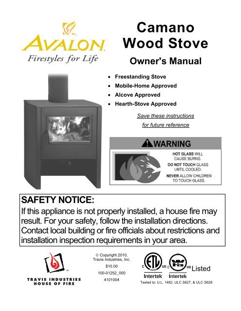
“<strong>Camano</strong><strong>Wood</strong> <strong>Stove</strong><strong>Owner's</strong> <strong>Manual</strong>• Freestanding <strong>Stove</strong>• Mobile-Home Approved• Alcove Approved• Hearth-<strong>Stove</strong> ApprovedSave these instructionsfor future referenceSAFETY NOTICE:If this appliance is not properly installed, a house fire mayresult. For your safety, follow the installation directions.Contact local building or fire officials about restrictions andinstallation inspection requirements in your area.© Copyright 2010,Travis Industries, Inc.$10.00100-01252_0004101004ListedTested to: U.L. 1482, ULC S627, & ULC S628
2 IntroductionIntroductionWe welcome you as a new owner of an Avalon <strong>Camano</strong> wood-burning stove. In purchasing a <strong>Camano</strong>you have joined the growing ranks of concerned individuals whose selection of an energy system reflectsboth a concern for the environment and aesthetics. The Avalon <strong>Camano</strong> is one of the finest appliancesthe world over. This manual will explain the installation, operation, and maintenance of this appliance.Please familiarize yourself with the <strong>Owner's</strong> <strong>Manual</strong> before operating your appliance and save themanual for future reference. Included are helpful hints and suggestions which will make the installationand operation of your new appliance an easier and more enjoyable experience. We offer our continualsupport and guidance to help you achieve the maximum benefit and enjoyment from your appliance.Important InformationNo other Avalon <strong>Camano</strong> appliance has the sameserial number as yours. The serial number isstamped onto the label on the back of the appliance.This serial number will be needed in case you requireservice of any type.Model:Serial Number:Purchase Date:Avalon <strong>Camano</strong>Mail your Warranty Card Today, and Save Your Billof Sale.To receive full warranty coverage, you will need toshow evidence of the date you purchased yourappliance. Do not mail your Bill of Sale to us.We suggest that you attach your Bill of Sale to thispage so that you will have all the information you needin one place should the need for service or informationoccur.Purchased From:© Travis Industries 100-01252_000 4101004
4 Safety PrecautionsThe viewing door must beclosed and latched duringoperation.Smoke from this appliance mayactive a smoke detector whenthe door is open.Never block free airflow throughthe air vents on this appliance.This appliance is designed andapproved for the burning of cordwood only. Do not attempt toburn any other type of fuel otherthan cord wood in thisappliance, it will void allwarranties and safety listings.GasASHESGasoline or other flammableliquids must never be used tostart the fire or "Freshen Up" thefire. Do not store or usegasoline or other flammableliquids in the vicinity of thisappliance.Ashes must be disposed in ametal container with a tight lidand placed on a noncombustiblesurface well awayfrom the home or structure.Do not touch the appliance whileit is hot and educate all childrenof the danger of a hightemperatureappliance. Youngchildren should be supervisedwhen they are in the same roomas the appliance.36"Keep furniture, drapes, curtains,wood, paper, and othercombustibles a minimum of 36"away from the front of theappliance.This appliance must be properlyinstalled to prevent thepossibility of a house fire. Theinstructions must be strictlyadhered to. Do not usemakeshift methods orcompromise in the installation.OkContact your local buildingofficials to obtain a permit andinformation on any installationrestrictions or inspectionrequirements in your area.Notify your insurance companyof this appliance as well.Inspect the chimney connectorand chimney at least twicemonthly and clean if necessary.Creosote may build up andcause a house fire.Do not connect this appliance toany chimney serving anotherappliance.TypeHTClayLinerThis appliance must beconnected to a listed hightemperature (UL 103 HT)residential type chimney or anapproved masonry chimney witha standard clay tile, or stainlesssteel liner.© Travis Industries 100-01252_000 4101004
Safety Precautions 5MobileHomeWhen installed in a mobilehome, this appliance must bebolted to the floor, have outsideair, and not be installed in thebedroom (Per H.U.D.requirements). Check with localbuilding officials.Do not place clothing or otherflammable items on or near thisappliance.Never try to repair or replaceany part of this appliance unlessinstructions are given in thismanual. All other work must bedone by a trained technician.Allow the appliance to coolbefore carrying out anymaintenance or cleaning.Do not make any changes ormodifications to an existingmasonry fireplace or chimney toinstall this appliance.Do not make any changes to theappliance to increasecombustion air.Overfiring the appliance maycause a house fire. If a unit orchimney connector glows, youare overfiring.This<strong>Manual</strong>Maintain the door and glass sealand keep them in goodcondition.Do not operate this heater withbroken or missing glass.Avoid placing wood against theglass when loading. Do notslam the door or strike the glass.Do not throw this manual away.This manual has importantoperating and maintenanceinstructions that you will need ata later time. Always follow theinstructions in this manual.Do not use a grate or otherdevice to elevate the fire off ofthe firebox floor. Burn the firedirectly on the bricks.Travis Industries, Inc. grantsno warranty, implied orstated, for the installation ormaintenance of yourappliance, and assumes noresponsibility of anyconsequential damage(s).© Travis Industries 100-01252_000 4101004
6 Features & SpecificationsInstallation Options• Freestanding• Freestanding in an Alcove• Freestanding in a Mobile HomeHeating SpecificationsFeatures• EPA Phase II Approved• 1.6 Cubic Foot Firebox Volume• Single Operating Control• Accepts Logs Up to 18" Long• Steel Plate Construction (1/4" & 3/16")• Heavy Duty Refractory Firebrick• Optional High-Tech BlowerApproximate Maximum Heating Capacity (in square feet)* 750 to 1,400Maximum BTU's per Hour (Cord <strong>Wood</strong> Calculation) 66,800Maximum Burn TimeUp to 8 Hours* Heating capacity will vary depending on the home's floor plan, degree of insulation, and the outsidetemperature. It is also affected by the quality and moisture level of the fuel.Dimensionsa5-3/4"146mm24-1/2"622mm5/8"16mm17-3/8"441mm29-1/2"749mmb(a) Dimensions are measured from the stove top.(b) Rubber-Tipped Leveling Bolts (at each corner).Figure 1Emissions4.4 Grams Per Hour (EPA Phase II Approved) – Tests conducted by E.E.S.P.C.© Travis Industries 100-01252_000 4101004
<strong>Stove</strong> Installation (for qualified installers only) 7SAFETY NOTICE:Please read this entire manual before you install and use your new room heater. Failure to followinstructions may result in property damage, bodily injury, or even death. Contact local building or fireofficials about restrictions and installation inspection requirements in your area.Planning The InstallationWe suggest that you have an authorized Travis Industries dealer install your stove. If you install thestove yourself, your authorized dealer should review your installation plans.Check with local building officials for any permits required for installation of this stove and notify yourinsurance company before proceeding with installation.We recommend using a slip-joint connector above the stove. This allows the flue to be disconnectedwhen removing the door (see “Removing the Door” on page 27).Preparation for Installation• Check for damage to the exterior of the stove (dents should be reported, scratches can be fixed byapplying touch up paint).• Check the interior of the firebox (replace cracked firebrick and make sure baffle is in place).The stove can be lightened by removing the firebricks and baffle (pg 28) - replace before operation.<strong>Stove</strong> Installation ConsiderationsThe table below details the six most common types of installations and the considerations for each type.Alternative methods of installation are available if they comply with local building codes.Installation TypeStandard Ceiling with a Factory Built Chimney(Page 15)Cathedral Ceiling with a Factory Built Chimney(Page 15)Exterior Factory Built Chimney(Page 16)Hearth <strong>Stove</strong> Positive Connection(Page 16)Hearth <strong>Stove</strong> Direct Connection(Page 17)Interior Masonry Chimney(Page 17)Considerations• Requires ceiling and roof penetration• Provides best draft• Cathedral style chimney support required• Provides best draft• Uses two elbows to route chimney outside• Exterior chimney is hidden from the room• Elbows reduce draft• Optional exterior chase reduces cold air blockage• Utilizes existing masonry or zero clearance (metal) chimney• Provides good draft due to full reline• Easier to clean than direct or horizontal hearth stove• Utilizes existing masonry or zero clearance (metal) chimney• Requires construction of a "block-off plate"• Draft reduced due to elbows & chimney cross section• Utilizes existing masonry chimney (not approved for zeroclearance (metal) fireplaces)Center DividerBack of <strong>Stove</strong>The center divider allows the installer to conceal the areaunder the stove. It is shipped in the forward position toallow for outside air and blower connection. If not usingthese accessories, it may be moved to the rear to allowmore room under the stove. The divider has keyhole-slotsto ease installation and removal. Pre-thread the screwholes before installing.© Travis Industries 100-01252_000 4101004
8 <strong>Stove</strong> Installation (for qualified installers only)Floor Protection Requirements• Floor protection must extend to the sides, rear, and front of the stove (see “Clearances” below forminimum floor protection).• Floor protection must be non-combustible and at least .018" thick (26 guage).<strong>Stove</strong> Placement RequirementsClearances may be reduced by methods specified in NFPA 211, listed wall shields, pipe shields, orother means approved by local building or fire officials.• <strong>Stove</strong> must be placed so that no combustibles are within, or can swing within (e.g. drapes, doors),36" of the front of the stove• If the stove is placed in a location where the ceiling height is less than 7', it must follow therequirements in the section "Alcove Installation Requirements"• Must maintain the clearances to combustibles listed below (drywall, furniture, etc.):Clearances• The following clearances must be met (see Figure 2 and Figure 3)Minimum ClearanceSinglewallConnectorReducedClearance*A Sidewall to stove 18" 13"B Backwall to stove 16-1/2” 9"C Cornerwall to stove 10" 7-1/2"D Connector to sidewall 27" 21-1/2"E Connector to backwall 19-1/2" 11-1/2"F Connector to cornerwall 19-1/2" 16-1/2"G Floor protection side and back 6” US 8” Canada 6” US 8” CanadaH Floor protection front 16” US 18” Canada 16” US 18” Canada*Reduced clearance installations require one of the chimneys and connectors listed below:AMERI-TEC model DCC with model HS chimneyDURAVENT model DVL with DURATEC or DURA-PLUS chimneyGSW Super Chimney Twenty-One connected directly to applianceI.C.C. Excel (2100-2 Can.) (103-HT USA) chimney with HP connectorMETALFAB model DW connector with TG chimneyOLIVER MACLEOD PROVENT model PV connector with model 3103 chimneySECURITY model DP connector with SECURITY model ASHT or S2100 chimneySELKIRK METALBESTOS model DS connector with model SSII chimneyStandard Masonry Chimney with any one of the above listed connectorsNOTE: Reduced clearance connectors may not connect to the flue collar – an appliance adapter may be required.NOTE: Standard residential installations with reduced clearance connector may use the clearancedetermined by the manufacturer of the connector for the connector to wall clearance or the clearancelisted in this manual. Offsets must be used to maintain the stove to wall clearance.© Travis Industries 100-01252_000 4101004
<strong>Stove</strong> Installation (for qualified installers only) 9Top View -Straight Installation(i) Measure rear and sideclearances from the stovetop.(j) Vent diameter variesdepending on brand andmodel.(k) Measure frontclearances from the stovetop.e24-1/2"g622mm5-3/4" 146mm g17-3/8" 441mmhbadijkFigure 2Top View -Corner Installationf24-1/2"g622mm5-3/4" 146mmg17-3/8" 441mmhcijkFigure 3© Travis Industries 100-01252_000 4101004
10 <strong>Stove</strong> Installation (for qualified installers only)Chimney Connector Requirements• Chimney connector is required from the flue collar of the stove to the factory-built chimney ormasonry chimney.• The chimney connector must be 6” diameter and a minimum 24 gauge black steel, or one of thereduced-clearance connectors listed on page 8.NOTE: Aluminum or galvanized steel is not allowed – these materials can not withstand the fluetemperatures and may give off toxic fumes when heated.NOTE: Standard residential installations may use single-wall connector (Mobile-Homes may not).• The chimney connector may not pass through a ceiling, attic, roof, closet, or any other concealedspace (use listed UL 103 HT chimney – see “Chimney Requirements for details). DO NOT USECONNECTOR PIPE AS CHIMNEY.• IN CANADA: Where passage through a wall, or partition of combustible construction is desired, theinstallation shall conform to CAN/CSA-B365, Installation Code for Solid-Fuel-Burning Appliances andEquipment.• The chimney connector should be as short and direct as possible. No more than 180 o of elbows (two90 o elbows, or two 45 o & one 90 o elbow, etc.) may be used for the entire system (connector andchimney).. Horizontal runs should slope upwards 1/4” per foot and be a maximum 36” long.• The chimney connector must be installed with the crimped end pointing downwards. This preventscreosote from leaking to the exterior of the pipe.• The chimney connector must be fastened to the stove and each adjoining section (and chimney).• Standard residential installations may use single-wall connector (Mobile-Homes may not)• Standard residential installations with reduced clearance connector may use the clearancedetermined by the manufacturer of the connector for the connector to wall clearance or the clearancelisted in this manual. Offsets must be used to maintain the stove to wall clearance. Mobile homesmust use the clearances listed in this manual under "Additional Requirements for Mobile HomeInstallations".© Travis Industries 100-01252_000 4101004
Chimney Requirements<strong>Stove</strong> Installation (for qualified installers only) 11• DO NOT CONNECT THIS UNIT TO A CHIMNEY FLUE SERVING ANOTHER APPLIANCE.• DO NOT CONNECT TO OR USE IN CONJUNCTION WITH ANY AIR DISTRIBUTION DUCTWORKUNLESS SPECIFICALLY APPROVED FOR SUCH INSTALLATIONS• IN CANADA: This appliance must be connected to a factory-built chimney conforming to CAN/ULC-S629, Standard for 650°C Factory-Built Chimneys.• UL 103 HT Chimney must be used from the first ceiling or floor penetration to the chimney cap.• Use 6" diameter type UL 103 HT chimney from one manufacturer (do not mix brands) or codeapproved masonry chimney with a flue liner.• Chimney must be fastened to each adjoining section.• Follow the chimney manufacturer's clearances and requirements.• Use the chimney manufacturer's fire stops, attic guards, roof supports, and flashings when passingthrough a ceiling (see “b” below).• No more than 180 o of elbows (two 90 o elbows, or two 45 o & one 90 o elbow, etc.) may be used for theentire system (connector and chimney).NOTE: Additional elbows may be allowed if draft is sufficient. Whenever elbows are used the draft isadversely affected. Additional chimney height may be required to boost draft.(a) Min. System Height 15’Max. System Height 33’(b) Roof Penetration and Termination (seechimney manufacturer’s requirements)(c) Chimney Sections(d) Floor Penetration (see chimney manufacturer’srequirements)(e) Min. air space to combustibles (see chimneymanufacturer’s requirements – typically 2”)(f) Connector – see “Chimney Connector” on theprevious page.bcdf} }}beafDraftingPerformanceFigure 4This appliance relies upon natural draft to operate. External forces, such as wind,barometric pressure, topography, or factors of the home (negative pressure from exhaustfans, chimneys, air infiltration, etc.), may adversely affect draft. Travis Industries can not beresponsible for external forces leading to less than optimal performance.© Travis Industries 100-01252_000 4101004
12 <strong>Stove</strong> Installation (for qualified installers only)Chimney Termination Requirements• Must have an approved cap (to prevent water from entering)• Must not be located where it will become plugged by snow or other material• Must terminate at least 3' above the roof and at least 2' above any portion of the roof within 10' (seeFigure 5)Slanted RoofsChimney mustextend 3'above the roofChimney must extend 2'above any portion of the roofwithin 10' of the chimneyFlat RoofsChimney mustextend 3'above the roofOutside Air RequirementsChimney must extend 2'above any portion of the roofwithin 10' of the chimney• Required for mobile homes & in certain localities (check with local building official)• Must not be drawn from an enclosed space (garage, unventilated crawl space)• Requires the outside air kit (sku 99200139 – see “a” below). The outside air kit attaches to thebottom of the stove (see “c” below).• Outside air duct must have a rodent screen and rain hood (“b”).• NOTE: Make sure the center divider under the stove is in the farthest forward position (see page 7).Back of <strong>Stove</strong>Figure 5abcFigure 6© Travis Industries 100-01252_000 4101004
<strong>Stove</strong> Installation (for qualified installers only) 13Alcove Installation RequirementsWhenever the stove is placed in a location where the ceiling height is less than 7' tall, it is considered analcove installation. Because of the reduced height, the special installation requirements listed below mustbe met.• Chimney connector and chimney must be one of the following types:AMERI-TEC model DCC with model HS chimneyDURAVENT model DVL with DURATEC or DURA-PLUS chimneyGSW Super Chimney Twenty-One connected directly to applianceI.C.C. Excel (2100-2 Can.) (103-HT USA) chimney with HP connectorMETALFAB model DW connector with TG chimneyOLIVER MACLEOD PROVENT model PV connector with model 3103 chimneySECURITY model DP connector with SECURITY model ASHT or S2100 chimneySELKIRK METALBESTOS model DS connector with model SSII chimneyStandard Masonry Chimney with any one of the above listed connectorsNOTE: Reduced clearance connectors may not connect to the flue collar – an appliance adapter may be required.• Alcoves are classified as combustible or non-combustible. Non-combustible alcoves must have wallsand a ceiling that are 3 1/2" thick of a non-combustible material (brick, stone, or concrete - see Figure7). This non-combustible material must be spaced and ventilated at least 1" off of all combustiblematerials (walls, ceiling, etc.) to allow air to move around the non-combustible walls and ceiling. Allother alcoves are considered combustible. The clearances below must be met:Minimum Clearance(See the Figure 7 below)CombustibleAlcoveNon-CombustibleAlcoveA Sidewall to stove 13" 6"B Backwall to stove 9" 2"D Connector to sidewall 21-1/2" 14-1/2"E Connector to backwall 11-1/2" 4-1/2"G Maximum depth of alcove 48" 48"H Minimum width of alcove 49-5/8" 35-5/8"J Minimum height of alcove 84" 6" above stove topNon-Combustible Alcove(a) Non-Combustible (brick)(b) Air Space with non-combustiblereinforcement(c) Combustible materialMin. 1"(25mm)Min. 3 1/2"(89mm)adebjcabhgFigure 7© Travis Industries 100-01252_000 4101004
14 <strong>Stove</strong> Installation (for qualified installers only)Mobile Home Requirements• Outside air must be installed - see "Outside Air Requirements" on page 12• Chimney connector and chimney must be one of the following types:AMERI-TEC model DCC with model HS chimneyDURAVENT model DVL with DURATEC or DURA-PLUS chimneyGSW Super Chimney Twenty-One connected directly to applianceI.C.C. Excel (2100-2 Can.) (103-HT USA) chimney with HP connectorMETALFAB model DW connector with TG chimneyOLIVER MACLEOD PROVENT model PV connector with model 3103 chimneySECURITY model DP connector with SECURITY model ASHT or S2100 chimneySELKIRK METALBESTOS model DS connector with model SSII chimneyStandard Masonry Chimney with any one of the above listed connectorsNOTE: Reduced clearance connectors may not connect to the flue collar – an appliance adapter may be required.• <strong>Stove</strong> placement must maintain the following clearances to combustibles (drywall, furniture, etc.)defabcMinimum Clearance(See the illustration above)A Sidewall to stove 13"B Backwall to stove 9"C Cornerwall to stove 7-1/2"D Connector to sidewall 21-1/2"E Connector to backwall 11-1/2"F Connector to cornerwall 16-1/2"Reduced ClearanceConnector• If using offsets, use the connector clearance listed in Figure 9, not theconnector manufacturer's clearance.• The appliance must be secured to the floor (consult your building official).Use an “L” bracket or other suitable means to secure the stove.• Mobile home installations require a spark arrester at the chimneytermination.• The appliance must be grounded to the chassis of the mobile home(consult your building official).• WARNING:DO NOT INSTALL IN SLEEPING ROOM.• CAUTION:THE STRUCTURAL INTEGRITY OF THE MOBILE HOMEFLOOR, WALL, AND CEILING/ROOF MUST BE MAINTAINED.12” Min.Figure 8Connector Clearance(as outlined above)<strong>Stove</strong> Clearance(as outlined above)Figure 9© Travis Industries 100-01252_000 4101004
Standard Ceilingwith a FactoryBuilt Chimney<strong>Stove</strong> Installation (for qualified installers only) 15Chimney Cap(See the section "ChimneyTermination Requirements"for more details)Chimney SectionsInsulationFollow the chimneymanufacturer's instructionsand clearances for floorpenetrations. A ceilingsupport is required, an atticinsulation shield is requiredwhere insulation is present.} }Follow the chimneymanufacturer's instructionsand clearances for roofpenetrations. A storm collarand flashing are required(some require a radiationshield).Minimum Air Space toCombustibles (SeeChimney Manufacturer'sInstructions)Cathedral Ceilingwith a FactoryBuilt ChimneyChimney Connector SectionsFloor Protection(See the section "FloorProtection Requirements"for more details)Chimney Cap(See the section "ChimneyTermination Requirements"for more details)Chimney SectionsMinimum Air Space toCombustibles (See ChimneyManufacturer's Instructions)Floor Protection(See the section "FloorProtection Requirements"for more details)ChimneyConnectorSections}Minimum 15'(4.57M)Maximum 33'(10.05M)<strong>Stove</strong> Clearances(See the section "<strong>Stove</strong>Placement Requirements"for more details)Follow the chimneymanufacturer's instructionsand clearances for roofpenetrations. A stormcollar, flashing, andcathedral-style chimneysupport are required(some require a radiationshield).Minimum 15'(4.57M)Maximum 33'(10.05M)<strong>Stove</strong> Clearances(See the section "<strong>Stove</strong>Placement Requirements"for more details)Figure 10Figure 11© Travis Industries 100-01252_000 4101004
}16 <strong>Stove</strong> Installation (for qualified installers only)Exterior FactoryBuilt ChimneyHearth <strong>Stove</strong>PositiveConnectionChimney Cap(See the section "ChimneyTermination Requirements"for more details)Chimney SectionsMinimum Air Space toCombustibles (SeeChimney Manufacturer'sInstructions)Min. 18"(457mm)clearance toceilingChimney ConnectorSectionsFloor Protection(See "FloorProtectionRequirements"for details)Wall BandsandSupportsNOTE: The entire fireplace andchimney must be clean, undamaged,and meet all local building codes(UBC, etc.). Damage must berepaired prior to installation. Thechimney must be 15' (4.57M) to 33'(10.05M) tall.CombustibleMantleFloor Protection(See the section"Floor ProtectionRequirements"for more details)Min. 18"(457mm)}Minimum 15' (4.57M)Maximum 33' (10.05M)<strong>Stove</strong> Clearances(See the section "<strong>Stove</strong>Placement Requirements"for more details)Follow the chimneymanufacturer'sinstructions andclearances for roofpenetrations. A stormcollar and flashing arerequired (somerequire a radiationshield).Insulated Tee(with cleanout )Follow the chimneymanufacturer'sinstructions andclearances for wallpenetrations. Awall radiation shield(thimble) isrequired.OptionalinsulatedchaseCap and flashingprevents water fromenteringAirtight InsulatedClean-OutRemove damperor wire it openSee the section"<strong>Stove</strong> PlacementRequirements" forminimum clearancesrequired.Figure 12The liner must bestainless steel connectoror flexible vent. Followthe liner manufacturer'sinstructions for installationand support.Figure 13© Travis Industries 100-01252_000 4101004
Hearth <strong>Stove</strong> DirectConnectionNOTE: This type oninstallation is notallowed in Canada.NOTE:Direct connections requireinstallation of an airtight,non-combustible block-offplate or damper adapter.Interior or ExteriorMasonry ChimneyNOTE: This type oninstallation is notallowed in Canada.NOTE:This type of installationrequires a UBC approvedmasonry connector orother method approved bythe NFPA 211 standard.See Chimney ConnectorRequirements on page 10for further details.<strong>Stove</strong> Installation (for qualified installers only) 17NOTE: The chimney must have a clay tileliner. If it does not, the installation must usea positive connection (full reline). The entirefireplace and chimney must be clean,undamaged, and meet all local buildingcodes (UBC, etc.). Damage must berepaired prior to installation. The chimneymust be 15' (4.57M) to 33' (10.05M) tall.Combustible MantleFloor Protection(See the section"Floor ProtectionRequirements" formore details)NOTE: The chimney must have aclay tile liner. If it does not, theinstallation must use a positiveconnection (full reline). The entirefireplace and chimney must beclean, undamaged, and meet alllocal building codes (UBC, etc.).Damage must be repaired prior toinstallation. The chimney must be15' (4.57M) to 33' (10.05M) tall.See the section "<strong>Stove</strong>Placement Requirements" forminimum clearances required.Chimney connector sectionsSee the section"Floor ProtectionRequirements"Min. 18"(457mm)Min. 18"(457mm)clearanceto ceilingClayLinerStainless steelchimney connectormust Extend 1' pastthe block-off plate orto the flue linerAirtightInsulatedClean-OutRemove damperor wire it openBlock-off plate ordamper adapterSee the section"<strong>Stove</strong> PlacementRequirements" forminimum clearancesrequired.Clay LinerMake sure theclean-out seals inplace.Figure 14This type ofinstallation requiresa UBC approvedmasonry connectoror a factory built(U.L. Listed) wallthimble.Figure 15© Travis Industries 100-01252_000 4101004
18 Operating Your ApplianceSafety NoticeIf this appliance is not properly installed, a house fire may result. For your safety, follow the installationdirections. Contact local building or fire officials about restrictions and installation inspectionrequirements in your area.Read and follow all of the warnings on pages 4 and 5 of this manual.Before Your First FireVerify the InstallationBefore starting the stove, verify that the stove is properly installed and all of the requirements in thismanual have been followed.Keep all flammable materials 36" away from the front of the stove (drapes, furniture, clothing, etc.).Curing the PaintThis heater uses a heat-activated paint that will emit some fumes whilestarting the first fire. Open doors and windows to the room to vent thesefumes. This typically lasts two to four hours. You may also notice oil burningoff of the interior of the heater. This rust-stopping agent will soon dissipate.Door Gasket - The door gasket might adhere to the paint on the front of theheater. Leave the door slightly ajar for the first fire and be careful whenopening the door after the first fire.2 to 4 hoursOver-Firing the <strong>Stove</strong>This stove was designed to operate at a high temperature. But due to differences in vent configuration,fuel, and draft, this appliance can be operated at an excessive temperature. If the stove top or other areastarts to glow red, you are over-firing the stove. Shut the air control down to low and allow the stove tocool before proceeding.Over-firing may lead to damage. If you are uncertain of over-firing conditions, we suggest placing astove thermometer (e.g. Rutland® Model 710) directly over the door on the stove top - temperaturesexceeding 800° are generally considered over-firing and will void the warranty.Opening the DoorLift thedoorhandle.Swingthe dooropen.The door becomes hot during use. Use a glove to open the door if the handle is hot.To prevent smoke from entering the room, open the air control before opening the door. You can alsoopen the door a small amount and let air enter the firebox.© Travis Industries 100-01252_000 4101004
20 Operating Your ApplianceAdjusting the Burn RateUse the air control slider to control the burn rate of the stove. See the illustration below for details.Approximate Air Control SettingsOvernight BurnMedium BurnMedium High BurnHigh BurnFully out to 9/32" open9/32" to 5/16" open5/16" to 7/16" open7/16" to full inThe air control becomes hot during operation - use gloves or a tool to prevent burns.Ash RemovalASHESThe air control may take several minutes to influence the burn rate. When making adjustments, youmay wish to let the stove burn for 10 minutes to gauge performance.Ashes should be placed in a metal container with a tight fitting lid. The closed container of ashesshould be placed on a noncombustible floor or on the ground, away from all combustiblematerials, pending final disposal. If the ashes are disposed of by burial in soil or otherwise locallydispersed, they should be retained in the closed container until all cinders have thoroughlycooled.© Travis Industries 100-01252_000 4101004
Optional Blower OperationOperating Your Appliance 21The blower will turn on once the stove is up to temperature. This is typically 15 to 30 minutes afterstarting the fire. Follow the directions below to alter the blower speed.OFFTurn the dial all the way counterclockwiseuntil it clicks off.LOBLOWERCONTROLThe high position is all the way counterclockwise,without clicking off.LOOFF HIHIGHBLOWERCONTROLTurn the dial all theway clockwise. LO LOWOFF HIOFF HIBLOWERCONTROLThe blower may be used to affect heat output (i.e.: to reduce heat output, turn the blower down).Route the power cord in a location where it will not come in contact with the appliance or become hot.Re-Loading the <strong>Stove</strong>Follow the directions below to minimize smoke spillage while re-loading the stove.1 Open the air control all the way (push it in).2 Open the door slightly. Let the airflow inside the firebox to stabilize before opening the doors fully.3 Load wood onto the fire.Overnight BurnThis stove is large enough to accommodate burn times up to eight hours. Follow the steps below toachieve an overnight burn.1 Move the air control to high burn and let the stove become hot (burn for approximately 15 minutes).2 Load as much wood as possible. Use large pieces if possible.3 Let the stove burn on high for 15 minutes to keep the stove hot, then adjust the air control to low.4 In the morning the stove should still be hot, with embers in the coal bed. Stir the coals and loadsmall pieces of wood to re-ignite the fire, if desired.Differences if chimney height and draft may lower overall burn times.Normal Operating SoundsCreaks and Clicks:The steel may creak or click when the stove heats upand cools down - this is normal.Blower Sounds:The blower will make a slight "humm" as itpushes air through the stove.Hint:Make sure the leveling bolts on legs are extended -preventing the hearth from amplifying any vibrations.© Travis Industries 100-01252_000 4101004
TroubleshootingProblemSmoke Enters Room DuringStart-UpKindling Does Not Start - FireSmoldersSmoke Enters Room While Re-LoadingOperating Your Appliance 23Possible Cause• Open the air control (pg. 20).• Cold Air Blockage - burn a piece of newspaper toestablish a draft.• If the flame is not getting enough air, a small crack inthe door is all that is needed.• Open the air control (pg. 20).• Not enough starter paper - use additional newspaper ifnecessary.• If the flame is not getting enough air, a small crack inthe door is all that is needed.• Open the air control before opening the door (pg. 20).• Let the air stabilize before fully opening the door.Then open the door approximately 1 inch. Let air gointo the firebox for a few seconds. Once the smokeappears to be flowing up the chimney consistently,open the door.• Insufficient Draft - Chimney height and outsideconditions can negatively affect draft. In these cases asmall amount of smoke may enter the home. Addingmore pipe or a draft-inducing cap may help.<strong>Stove</strong> Does Not Burn Hot Enough • <strong>Wood</strong> is Wet - see the section "Selecting <strong>Wood</strong>" onpage 22 for details on wood.• Make sure the air control is all the way open. Slide thecontrol back and forth to insure the control is not stuck.• Insufficient Draft - Chimney height and outsideconditions can negatively affect draft. In these casesthe fire may burn slowly. Adding more pipe or a draftinducingcap may help.Blower Does Not Run • <strong>Stove</strong> is Not Up to Temperature - This is normal. Theblower will come on when the stove is hot - usually 15to 30 minutes.<strong>Stove</strong> Does Not Burn LongEnough• Electricity is Cut to the Blower - Check the householdbreaker or fuse to make sure it is operable.• Depending upon wood, draft, and other factors, theburn time may be shorter then stated. Make sure thedoors are sealing and not allowing air into the firebox -See the section "Door and Glass Inspection" on page25 for details.• Check the ash bed for coals. Often, coals are stillglowing under a slight bed of flyash. By raking theseinto a pile you can re-start your stove quickly.© Travis Industries 100-01252_000 4101004
24 Maintaining Your ApplianceFailure to properly maintain and inspect your appliance may reduce the performance and life of theappliance, void your warranty, and create a fire hazard.Establish a routine for the fuel, wood burner and firing technique. Check daily for creosote build-up untilexperience shows how often you need to clean to be safe. Be aware that the hotter the fire the lesscreosote is deposited, and weekly cleaning may be necessary in mild weather even though monthlycleaning may be enough in the coldest months. Contact your local municipal or provincial fire authorityfor information on how to handle a chimney fire. Have a clearly understood plan to handle a chimneyfire.Daily Maintenance (while stove is in use)Remove Ash (if necessary)• Ash removal is not required once it builds up. 1/2" to 1" of ash may be desirable because it slows theburn rate. Generally, remove ash once it has built up over 1". Follow the directions below to removeash.1 Let the stove cool completely (at least two hours after the last coal has extinguished).2 Place a cloth or cardboard protector over the hearth to catch ash and protect againstscratching.3 Open the door and scoop the ash into a metal container with a tight fitting lid. The ASHESclosed container of ashes should be placed on a noncombustible floor or on theground, away from all combustible materials, pending final disposal.Improperly disposed ashes lead to fires. Hot ashes placed in cardboard boxes, dumped in back yards,or stored in garages, are recipes for disaster.<strong>Wood</strong>-burning stoves are inherently dirty. During cleaning have a vacuum ready to catch spilled ash(make sure ash is entirely extinguished).There are vacuum cleaners specifically made to remove ash (even if the ash is warm). Contact yourdealer for details.Clean the Glass (if necessary)This appliance has an airwash to keep the glass clean. However, burning un-seasoned wood or burningon lower burn rates leads to dirtier glass (especially on the sides). Clean the glass by following thedirections below. Do not clean glass with abrasive cleaners.Allow the stove to fully cool. Apply glasscleaner or soapy water to the inside ofthe glass. Wipe with newspaper or apaper towel.For Stubborn Creosote:Dip newspaper or a paper towel in coolashes and wipe it on the glass. The ashacts as a light abrasive.The glass will develop a very slight haze over time. This is normal and will not affect viewing of the fire.© Travis Industries 100-01252_000 4101004
Maintaining Your Appliance 25Monthly Maintenance (while appliance is in use)Make sure the appliance has fully cooled prior to conducting service.Door and Glass InspectionThe door must form an air-tight seal to the firebox for the stove to work correctly. Inspect the door gasketto make sure it forms an air-tight seal to the firebox.High-Temperatureanti-sieze may beused on the doorhinges to eliminatesqueaks.If the glass is damaged,replace it - see“Replacement Parts” fordetails.Use RTV hightemperature silicone toadhere any loosegasket.Severely frayed or thread-baregasket should be replaced.The door latch should pull the door against the face of the stove (but not so tight as to not allow fullhandle rotation). If the latch requires adjustment, follow the directions below.9/16" WrenchNutCamDoor Frame (with gasket)WashersDoor HandleDoor Cam Adjustment:To tighten the door cam, remove the door handle and discard one of the washersbetwen the door frame and cam. To loosen the door cam, add a washer betweenthe door frame and cam.Creosote - Formation and Need for RemovalWhen wood is burned slowly, it produces tar and other organic vapors, which combine with expelledmoisture to form creosote. The creosote vapors condense in the relatively cool chimney flue of a slowburningfire. As a result, creosote residue accumulates on the flue lining. When ignited, this creosotemakes an extremely hot fire. The chimney and chimney connector should be inspected at least onceevery two months during the heating season to determine if a creosote buildup has occurred. If creosotehas accumulated, it should be removed to reduce the risk of a chimney fire.If you are not certain of creosote inspection, contact your dealer or local chimney sweep for a fullinspection. Excess creosote buildup may cause a chimney fire, that may result in property damage,injury, or death.Operating this appliance continually at a low burn rate (air starvation) or using green (un-seasonedwood) will increase the formation of creosote.© Travis Industries 100-01252_000 4101004
26 Maintaining Your ApplianceYearly MaintenanceMake sure the appliance has fully cooled prior to conducting service.Touch Up PaintIncluded with the owner's pack of this appliance is a can of <strong>Stove</strong>-Brite®paint. To touch up nicks or dulled paint, apply the paint while the appliance iscool. Sand rusted or damaged areas before preparation (use 120 gritsandpaper). Clean and dry the area to prepare the surface. Wait at least onehour before starting the appliance. The touched up area will appear darkerthan the surrounding paint until it cures from heat. Curing will give off somefumes while curing – open windows to ventilate.Touch-UpPaintCleaning the Air Duct and Blower (if applicable)Use a vacuum to clean the air ducts (channels). This prevents dust from burning and creating odors.The optional blower should be vacuumed every year to remove any buildup of dust, lint, etc.BOTTOM OFSTOVEUse a vacuum cleaner to remove anybuildup on the screens of the blower.Firebrick and Baffle InspectionUse the illustration on page 28 as a reference for checking the following items. Make sure the applianceis cool before proceeding.Baffle Firebricks - check the bricks along the ceiling of the firebox to make sure they are intact and haveno gaps between them. Slide the bricks to eliminate any gaps.Baffle Supports - make sure the front and back baffle supports in are place and not degraded. Slightscaling or rusting of the metal is normal.Secondary Air Tubes - Check the air tubes and collars to make sure they are intact and not severelydeteriorated. Slight scaling or rusting of the metal is normal. Make sure the roll pins hold the air tubes inplace.Floor and Wall Firebricks - replace any severely damaged firebrick along the side or floor of the firebox.© Travis Industries 100-01252_000 4101004
Maintaining Your Appliance 27Door Parts4513210 7 968ID # Description Qty Part # ID # Description Qty Part #1 Glass Gasket 1 250-00173 2 <strong>Camano</strong> Glass 1 250-020733 Glass Clip w Gasket– 3 Hole 2 250-00174 4 Door Gasket 1 250-001785 RTV High Temp. 600° Silicone 6 <strong>Camano</strong> Door Handle Asbly 1 250-020747 <strong>Camano</strong> Door Handle (phenolic) 1 91001605 8 Door Washer 1 250-003649 Door Cam 1 250-00598 10 Screws (8) 8-32 x 1/2” Torx 1 225-20039Replacing the GlassThe glass must not contact the door retainer or glass clips directly. The glass gasket and glass clipgaskets insulate the glass to prevent cracking. Do not over-tighten the glass clips.Replacing the Door GasketThe door gasket inserts into the outer groove of the door. RTV High temp silicone holds it in place.Before installing, remove any residual cement. Lay the gasket in place (start at the lower right corner)and cut off any excess gasket (do not stretch the gasket. You may need to open and close the doorrepeatedly to get the gasket to seat fully.Replacing the Door HandleSee the illustration above for a component list (see pg. 25 for details on adjusting the door).Removing the DoorThe stove top must be removed to lift the door off the hinges. To remove the stove top, disconnect theflue, remove the four screws securing this stove top to the back panel, and slide it forward away from thestove. When re-installing, make sure the two clips under the stove top engage the slots on the front ofthe stove.© Travis Industries 100-01252_000 4101004
28 Maintaining Your ApplianceFirebox Parts55556234155556557ID # Description Qty Part # ID # Description Qty Part #1 Baffle Support "S" Bar 1 99900294 2 Air Tube with Sleeve 3 989002323 Air Tube Roll Pins 6 98900357 4 Air Tube Retainer Sleeve 3 250-000425 Brick - 9" x 4.5" un-cut 16 251-00000 6 Brick, Cut - 9" x 2.25" 3 251-000017 Brick, Cut - 9" x 1.375" 2 251-00018Floor and Side Firebrick Removal & ReplacementDo not pry firebrick - they chip and crack easily. Remove the floor firebricks first. The side firebrickare removed later because they are pinned in place by the floor firebrick. Clean the firebox prior toreplacing the firebrick.© Travis Industries 100-01252_000 4101004
Baffle Removal & ReplacementMaintaining Your Appliance 29The baffle is held up by the front air tube. Make sure to support the baffle after removing the air tubes.• Lift the four baffle firebricks then lift the baffle deflector up and over its resting postion.• Slide the bricks forward and tilt them downwards to remove.Air Tube Removal & ReplacementAll three air tubes are identical.Air Tube CollarAir TubeaRemove the left pin on the air tube collarRoll PinbSlide the air tube to the left, swing itdown and remove from the firebox.Baffle Removal & ReplacementThe baffle is held up by the front air tube. Make sure to support the baffle after removing the air tubes.• Lift the four baffle firebricks then lift the baffle deflector up and over its resting postion.• Slide the bricks forward and tilt them downwards to remove.© Travis Industries 100-01252_000 4101004
30 Limited 7 Year WarrantyTo register your TRAVIS INDUSTRIES, INC. 7 Year Warranty, complete the enclosed warranty card and mail itwithin ten (10) days of the appliance purchase date to: TRAVIS INDUSTRIES, INC., 4800 Harbour Pointe Blvd.SW, Mukilteo, WA 98275. TRAVIS INDUSTRIES, INC. warrants this appliance (appliance is defined as theequipment manufactured by Travis Industries, Inc.) to be defect-free in material and workmanship to the originalpurchaser from the date of purchase as follows:Check with your dealer in advance for any costs to you when arranging a warranty call.Mileage or service charges are not covered by this warranty. This charge can vary from store to store.Years 1 & 2 - COVERAGE: PARTS & LABOR• Firebox Assembly:Firebox, Baffle Supports, Air Tubes, Air Channels, Convection Chamber• Door Assembly:Cast Door, Latch Assembly, Glass Retainers• Air Control AssemblySlider Plate, Pressure Plate• Ceramic GlassGlass (breakage from thermal shock)• FirebrickBreakage from thermal shock• AccessoriesLegs, Pedestal, Blower• Re-Installation AllowanceIn cases where heater must be removed from home for repairs, a partial cost of re-installation is covered(pre-authorization required)• One-Way Freight AllowanceOne-way freight allowance on pre-authorized repair done at factory is covered.Exclusions: Paint, GasketingYears 3 THROUGH 5 - COVERAGE: PARTS & LABOR• Firebox Assembly:Firebox, Baffle Supports, Air Tubes, Air Channels, Convection Chamber• Air Control AssemblySlider Plate, Pressure Plate• Door Assembly:Cast Door, Latch Assembly, Glass Retainers• One-Way Freight AllowanceOne-way freight allowance on pre-authorized repair done at factory is covered.Exclusions: Paint, Gasketing, Accessories (Legs, Pedestal, Panels, Blower), Glass, Firebrick, Re-Installation AllowanceYears 6 THROUGH 7 - COVERAGE: PARTS• Firebox Assembly:Firebox, Baffle Supports, Air Tubes, Air Channels, Convection Chamber• Air Control AssemblySlider Plate, Pressure Plate• Door Assembly:Cast Door, Latch Assembly, Glass RetainersExclusions: Paint, Gasketing, Accessories (Legs, Pedestal, Panels, Blower), Glass, Firebrick, Re-Installation Allowance, One-Way Freight Allowance, Labor ChargesPage 1 of 2© Travis Industries 100-01252_000 4101004
Limited 7 Year Warranty 31CONDITIONS & EXCLUSIONS1. This new appliance must be installed by a qualified installer. It must be installed, operated, and maintained at all times in accordance withthe instructions in the Owner’s <strong>Manual</strong>. Any alteration, willful abuse, accident, neglect, or misuse of the product shall nullify this warranty.2. This warranty is nontransferable, and is made to the ORIGINAL purchaser, provided that the purchase was made through an authorizedTravis dealer.3. Discoloration and some minor expansion, contraction, or movement of certain parts and resulting noise, is normal and not a defect and,therefore, not covered under warranty.4. This warranty does not cover misuse of the stove. Misuse includes over-firing (operation where the connector or stove may glow red) of thisappliance can cause serious damage and will nullify this warranty. Misuse includes use of salt saturated wood, chemically treated wood, orany fuel not recommended in the manual.5. Damage to the stove due to improper break-in procedures (see manual for proper break in).6. The salt air environment of coastal areas or a high humidity environment can be corrosive to the castings. These conditions can be corrosiveand can cause the cast iron to rust. This warranty does not cover any damage caused by a salt air or high humidity environment.7. Damage to the appliance while it is in transit is not covered by this warranty, but is subject to a claim against the common carrier.8. The warranty, as outlined within this document, does not apply to the chimney components or other Non-Travis accessories used inconjunction with the installation of this product. If in doubt as to the extent of this warranty, contact your authorized Travis retailer beforeinstallation.9. Travis Industries will not be responsible for inadequate performance caused by environmental conditions such as nearby trees, buildings,roof tops, wind, hills or mountains or negative pressure or other influences from mechanical systems such as furnaces, fans, clothes dryers,etc.10. This Warranty is void if:a. The appliance has been operated in atmospheres contaminated by chlorine, fluorine or other damaging chemicals.b. The appliance is subject to submersion in water or prolonged periods of dampness or condensation.c. Any damage to the appliance, combustion chamber, heat exchanger or other components due to water, or weather damage which isthe result of, but not limited to, improper chimney/venting installation.11. Exclusions to this 5 Year Warranty include: injury, loss of use, damage, failure to function due to accident, negligence, misuse, improperinstallation, alteration or adjustment of the manufacturer's settings of components, lack of proper and regular maintenance, damage incurredwhile the appliance is in transit, alteration, or act of God.12. This 5 Year warranty excludes damage caused by normal wear and tear, such as paint discoloration or chipping, worn or torn gasketing,chipped or cracked firebrick, etc. Also excluded is damage to the appliance caused by abuse, improper installation, modification of theappliance, or the use of fuel other than that for which the appliance is configured (use cord wood only).13. Damage to brass or plated surfaces caused by fingerprints, scratches, melted items, or other external sources left on the surfaces from theuse of abrasive cleaners is not covered in this warranty. Damage to the surfaces from over-firing (operation where the steel may glow red) isnot covered in this warranty.14. TRAVIS INDUSTRIES, INC. is free of liability for any damages caused by the appliance, as well as inconvenience expenses and materials.Incidental or consequential damages are not covered by this warranty. In some states, the exclusion of incidental or consequential damagemay not apply.15. This warranty does not cover any loss or damage incurred by the use or removal of any component or apparatus to or from the Travisappliance without the express written permission of TRAVIS INDUSTRIES, INC. and bearing a TRAVIS INDUSTRIES, INC. label ofapproval. This warranty does not cover a stove repaired by someone other than a Travis Industries authorized dealer.16. Any statement or representation of Travis products and their performance contained in Travis advertising, packaging literature, or printedmaterial is not part of this 5 year warranty.17. This warranty is automatically voided if the appliance’s serial number has been removed or altered in any way. If the appliance is used forcommercial purposes, it is excluded from this warranty.18. No dealer, distributor, or similar person has the authority to represent or warrant Travis products beyond the terms contained within thiswarranty. TRAVIS INDUSTRIES, INC. assumes no liability for such warranties or representations.19. Travis Industries will not cover the cost of the removal or re-installation of hearths, facing, mantels, venting or other components.20. If for any reason any section of this warranty is declared invalid, the balance of the warranty remains in effect and all other clauses shallremain in effect.21. This 5 year warranty is the only warranty supplied by Travis Industries, Inc., the manufacturer of the appliance. All other warranties, whetherexpress or implied, are hereby expressly disclaimed and purchaser’s recourse is expressly limited to the warranties set forth herein.IF WARRANTY SERVICE IS NEEDED:1. If you discover a problem that you believe is covered by this warranty, you MUST REPORT it to your Travis dealer WITHIN 30 DAYS, givingthem proof of purchase, the purchase date, and the model name and serial number.2. Travis Industries has the option of either repairing or replacing the defective component.3. If your dealer is unable to repair your appliance’s defect, he may process a warranty claim through TRAVIS INDUSTRIES, INC.,including the name of the dealership where you purchased the appliance, a copy of your receipt showing the date of the appliance’spurchase, and the serial number on your appliance. At that time, you may be asked to ship your appliance, freight charges prepaid,to TRAVIS INDUSTRIES, INC. TRAVIS INDUSTRIES, INC., at its option, will repair or replace, free of charge, your appliance if it isfound to be defective in material or workmanship within the time frame stated within this 5 year warranty. TRAVIS INDUSTRIES,INC. will return your appliance, freight charges (years 1 to 3) prepaid by TRAVIS INDUSTRIES, INC., to your regional distributor, ordealership.4. Check with your dealer in advance for any costs to you when arranging a warranty call. Mileage or service charges are not covered bythis warranty. This charge can vary from store to store.5. Any appliance or part thereof that is repaired or replaced during the limited warranty period will be warranted under the terms of thelimited warranty for a period not to exceed the remaining term of the original limited warranty or six(6) months, whichever is longer.Page 2 of 2© Travis Industries 100-01252_000 4101004
CM32 Listing LabelListing LabelHOT WHILE IN OPERATION. DO NOT TOUCH. CONTACT MAY CAUSE SKIN BURNS.KEEP FURNISHINGS AND COMBUSTIBLE MATERIAL A CONSIDERABLE DISTANCEAWAY. SEE NAMEPLATE AND INSTRUCTIONS. DO NOT OVERFIRE. IF HEATER OR CHIMNEY CONNECTORGLOWS, YOU ARE OVERFIRING. INSPECT AND CLEAN CHIMNEY AND CONNECTOR FREQUENTLY.UNDER CERTAIN CONDITIONS OF USE, CREOSOTE BUILDUP MAY OCCUR RAPIDLY. DO NOT USE GRATEOR ELEVATE FIRE. BUILD FIRE DIRECTLY ON HEARTH. OPERATE ONLY WITH FIREBRICK IN PLACE.OPERATE ONLY WITH DOOR CLOSED. OPEN FEED DOORS TO FEED FIRE ONLY. USE OF OTHER FUELSMAY DAMAGE THE HEATER AND CREATE A HAZARDOUS CONDITION.TYPE OF FUEL: SOLID WOOD ONLY.DO NOT REMOVE THIS LABELCONTACT LOCAL BUILDING OR FIRE OFFICIALS ABOUT INSTALLATION AND RESTRICTIONS IN YOUR AREA.SUITABLE FOR USE IN CONVENTIONAL RESIDENTIAL INSTALLATIONS, MANUFACTURED HOMES AND ALCOVES.Report No. 100217684PRT-001Control No. 4000515MODEL:CAMANOCertified for USA and CanadaTested to: UL 1482 and ULC S627-00SERIAL NO:PREVENT HOUSE FIRES - Install and use only in accordance with the manufacturer’s installation and operating instructions. Contact your local building or fire officialsabout restrictions and installation inspection in your area. Refer to local building codes and manufacturer’s instructions for precautions required for passing achimney through a combustible wall or ceiling. Do not run a chimney connector through a combustible wall or ceiling. Do not connect this unit to a chimney flueserving another appliance. Clearances may be reduced by methods specified in NFPA 211, listed wall shields, pipe shields, or other means approved by local buildingor fire officials.FREESTANDING INSTALLATIONSTANDARD RESIDENTIAL FREESTANDING INSTALLATIONS REQUIRE: 6” diameter, minimum 24 MSG black, with listed UL-103 HT factory-built chimney, suitable foruse with solid fuels or masonry chimney. Pedestal or legs are required.ALCOVE INSTALLATIONS REQUIRE: One of the Listed doublewall connectors listed below. Pedestal or legs are required.MANUFACTURED HOME AND REDUCED CLEARANCE INSTALLATIONS REQUIRE: One of the Listed doublewall connectors listed below. In addition, manufacturedhome installations require outside air - use the optional pedestal or outside air boot.AMERI-TEC model DCC connector with model HS chimneyDURA-VENT model DVL connector with DURA-PLUS chimneyGSW-JAKES EVANS SUPERPIPE 2100I.C.C. EXCEL (103-HT) chimney with HP connectorMETALFAB model DW connector with TG chimneyOLIVER MACLEOD PROVENT model PV connector with model 3103 chimneySECURITY model DP connector with SECURITY model ASHT or S2100 chimneySELKIRK METALBESTOS model DS connector with model SSII chimneyA. Sidewall to UnitB. Backwall to UnitC. Cornerwall to UnitD. Sidewall to ConnectorE. Backwall to ConnectorF. Cornerwall to ConnectorG. Side & Rear Floor ProtectionH. Front Floor ProtectionSinglewall ConnectorConventional ResidentialInstallations18 in. (458 mm)16.5 in. (420 mm)10 in. (254 mm)27 in. (686 mm)19.5 in. (496 mm)19.5 in. (496 mm)US: 6 in. (153 mm) / CAN: 8 in. (204 mm)US: 16 in. (407 mm) / CAN: 18 in. (458 mm)Manufactured Home, Alcove and ReducedClearance Installations(Requires Doublewall Connector)13 in. (331 mm)9 in. (229 mm)7.5 in. (191 mm)21.5 in. (547 mm)11.5 in. (293 mm)16.5 in. (420 mm)US: 6 in. (153 mm) / CAN: 8 in. (204 mm)US: 16 in. (407 mm) / CAN: 18 in. (458 mm)SIDEWALLFREESTANDING CLEARANCE DIAGRAM ALCOVE SPECIFICATIONS FLOOR PROTECTION DIAGRAMBACKWALLDAESTOVEB45˚ADJACENT WALLSTOVEFCADJACENT WALLMax. Alcove Depth:Min. Alcove Height:Min. Alcove Width:48 in. (1220 mm)See Owner’s <strong>Manual</strong>See Owner’s <strong>Manual</strong>FLOOR PROTECTORGHGSTOVEGFRONTFloor protection must be a non-combustiblematerial extending beneath the heater and tothe front, sides and back as indicated. SeeOwner’s <strong>Manual</strong> for examples of non-combustiblematerials that can be used.Do not obstruct space beneath heater.Electrical Rating:Optional Blower:115V., 60 Hz, 1.8 Amps# 99000138Do not route power cord under or in front of appliance.Replace glass only with 5mm neoceramic orceramic glass.Manufactured by:TRAVIS INDUSTRIES, INC.4800 Harbour Pointe Blvd. SWMukilteo, WA 98275www.travisproducts.comU.S. ENVIRONMENTAL PROTECTION AGENCYCertified to comply with July 1990 particulate emission standards.Made in U.S.A.DATE OF MANUFACTURE2010 2011 2012 2013 Jan Feb Mar Apr May Jun Jul Aug Sep Oct Nov Dec0893© Travis Industries 100-01252_000 4101004
Rear Blower Installation (Part # 99000138)The rear blower improves heat transfer by pushing heated airthrough the convection channel. Operating instructions aredescribed in the section "Blower Operation".1 On some models you will need to remove the twoknockouts under the stove (see illustration to the right).2 Follow the directions below to install the thermodisk.Optional Equipment 33Snap DiskAssemblyWedge the snap disk into theair chamber on the left side 6”from the front.Bend these legs onthe snap disk if itdoes not fit tightly3 Install the wire clip following the directions below.Front of <strong>Stove</strong>Twist the wires together and feed themthrough the convection chamber andout either knockout.Snap DiskWiresWire ClipSlide the wire clipover the edge of thestrip of metal betweenthe two knock-outs.Feed the two snap disk wires intothe eye of the wire clip. Removeall slack from the wire, makingsure not to dislodge the snap disk.Pinch the eye of the wire clip tosecure the wires.WARNING:To prevent electrical shock, thewires must be secured so they donot contact the firebox above theconvection channel.4 Attach the blowerfollowing thedirections to theright.Position the blower near the rear of the stove. Connect thesnap disk wires to the blower wires and tuck all excess wireinto the blower box, making sure it does not contact any hot ormoving parts. When installing the blower, make sure thesewires do not become loose. Attach the blower to the stove withthe three screws included with the blower.3/8" WrenchPlug the blower in. Do not route thepower cord under or over the stoveor in a location where it may becomedamaged.© Travis Industries 100-01252_000 4101004
34 IndexAir Control ............................................................. 20Air Tube Part Number ........................................... 28Air Tube Removal & Replacement ........................ 29Alcove ................................................................... 13Ash Disposal ......................................................... 24Baffle Parts ........................................................... 28Baffle Removal and Replacement ......................... 29Blower Cleaning .................................................... 26Blower Does Not Run (Troubleshooting) ............... 23Blower Installation (rear) ....................................... 33Blower Operation (optional) ................................... 21Burn Rate .............................................................. 20Center Divider ....................................................... 7Cathedral Ceiling ................................................... 15Ceiling Penetration ................................................ 10Chimney Cleaning ................................................. 25Chimney Inspection (Creosote) ............................. 25Chimney Requirements ......................................... 10Chimney Termination Requirements ..................... 12Cleaning the Ash ................................................... 24Cleaning the Glass ................................................ 24Clearances (stove) ................................................ 8Close Clearance Connectors ................................ 8Connector Requirements ...................................... 10Creosote Check .................................................... 25Daily Maintenance ................................................. 24Dimensions ........................................................... 6Door and Glass Inspection .................................... 25Door Assembly ...................................................... 27Door Gasket Replacement .................................... 27Door Handle Replacement .................................... 27Door Opening ........................................................ 18Door Parts ............................................................. 27Draft Performance ................................................. 10Elbows (Chimney) ................................................. 10Emissions .............................................................. 6EPA Approval ........................................................ 6Exterior Chimney ................................................... 12Features ................................................................ 6Fire Starting........................................................... 19Firebox Assembly .................................................. 28Firebox Parts ......................................................... 28Firebrick and Baffle Inspection .............................. 26Firebrick Removal & Replacement ........................ 28Floor Protection Requirements (stove) .................. 8Glass Cleaning ...................................................... 24Glass Replacement ............................................... 27Hearth (Floor Protection - <strong>Stove</strong>) .......................... 8Hearth <strong>Stove</strong> ......................................................... 17Heating Specifications ........................................... 6Hints for Burns ...................................................... 22Installation Options ................................................ 6Installation (stove) ................................................. 7Listing Label .......................................................... 32Maintenance .......................................................... 24Mobile Home Requirements .................................. 14Monthly Maintenance ............................................ 25Noise (Normal Operating Sounds) ........................ 21Non-Combustible Alcove ....................................... 13Opening the Door .................................................. 18Operation .............................................................. 18Outside Air ............................................................ 12Over-Firing the <strong>Stove</strong> ............................................ 18Overnight Burn ...................................................... 21Paint (Touch-Up Paint) .......................................... 26Paint Curing .......................................................... 18Rear Blower Installation ........................................ 33Re-Loading the <strong>Stove</strong> ........................................... 21Safety Label .......................................................... 32Safety Precautions ................................................ 4Smell (from paint curing) ....................................... 18Smoke Enters Room (Troubleshooting) ................ 23Sounds (Normal Operating Sounds) ..................... 21Starting a Fire ........................................................ 19<strong>Stove</strong> Does Not Burn Long Enough ...................... 23<strong>Stove</strong> is Not Hot Enough (Troubleshooting) .......... 23Table of Contents .................................................. 3Touch-Up Paint ..................................................... 26Troubleshooting (Operation) ................................. 23Warranty Card ....................................................... 2Warranty................................................................ 30<strong>Wood</strong> ..................................................................... 22Yearly Maintenance............................................... 26© Travis Industries 100-01252_000 4101004