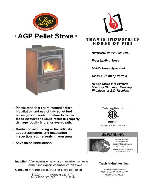
AGP Pellet Stove - Avalon
AGP Pellet Stove - Avalon
AGP Pellet Stove - Avalon

You also want an ePaper? Increase the reach of your titles
YUMPU automatically turns print PDFs into web optimized ePapers that Google loves.
4 Safety PrecautionsHOT WHILE IN OPERATION.KEEP CHILDREN, CLOTHING,AND FURNITURE AWAY.CONTACT MAY CAUSE SKINBURNS.Educate all children of the danger ofa high-temperature heater. Youngchildren should be supervised whenthey are in the same room as theheater.OkContact your local building officialsto obtain a permit and informationon any installation restrictions orinspection requirements in yourarea. Notify your insurancecompany of this appliance as well.Do not operate the heater if yousmell smoke coming from theheater. Turn the MODE switch to"OFF", monitor your heater, and callyour dealer.Do not unplug the heater if yoususpect a malfunction. Turn theMODE SWITCH to "OFF" andperiodically inspect the heater.GasASHESNever use gasoline, gasoline-typelantern fuel, kerosene, charcoallighter fluid, or similar liquids to startor “freshen up” a fire in this heater.Keep all such liquids well away fromthe heater while it is in use.Do not store solid fuel or place suchfuel within heater installationclearances or within the spacerequired for charging and ashremoval.Ashes should be placed in a metalcontainer with a tight-fitting lid. Theclosed container of ashes should beplaced on a noncombustible floor oron the ground, well away from allcombustible materials, pending finaldisposal. If the ashes are disposed ofby burial in soil or otherwise locallydispersed, they should be retained inthe closed container until all cindershave been thoroughly cooled.Never try to repair or replace anypart of the heater unlessinstructions are given in thismanual. All other work should bedone by a trained technician.The viewing door and ashpan mustbe closed and latched duringoperation.This unit must be properly installedto prevent the possibility of a housefire. The instructions must be strictlyadhered to. Do not use makeshiftmethods or compromise in theinstallation.This heater is designed and approvedfor pelletized wood fuel only.© Travis Industries 4130924 100-01330_004
6 Safety PrecautionsThisManualDo not throw this manual away.This manual has importantoperating and maintenanceinstructions that you will need at alater time. Always follow theinstructions in this manual.Disconnect the power beforeperforming any maintenance.The exhaust system should bechecked at least twice a year forany build-up of soot or creosote.Travis Industries, Inc. grants nowarranty, implied or stated, forthe installation or maintenance ofyour appliance, and assumes noresponsibility of anyconsequential damage(s).DO NOT INSTALL A FLUE DAMPER IN THE EXHAUST VENTING SYSTEM OF THIS UNIT.DO NOT CONNECT THIS UNIT TO A CHIMNEY FLUE SERVING ANOTHER APPLIANCE.INSTALL VENT AT CLEARANCES SPECIFIED BY THE VENT MANUFACTURER.Soot and Flyash: Formation and Need for Removal – The products of combustion will containsmall particle of flyash. The flyash will collect in the exhaust venting system and restrict theflow of the flue gases. Incomplete combustion, such as occurs during startup, shutdown, orincorrect operation of the room heater will lead to some soot formation which will collect inthe exhaust venting system. The exhaust venting system should be inspected at least onceevery year to determine if cleaning is necessary.NEVER USE SUBSTITUTE MATERIALS FOR ANY PURPOSE ON THIS APPLIANCE.Establish a routine for fuel, wood burner and firing technique. Check for creosote build-updaily until you know how often to clean the appliance for safe operation. Be aware that thehotter the fire, the less creosote is deposited, and weekly cleaning may be necessary in mildweather even though monthly cleaning may be enough in the coldest months. Contact yourmunicipal or provincial fire authority for information on how to handle a chimney fire. Have aclearly understood plan in place for how to handle a chimney fire.Do not burn this stove if unburned pellets are in the ashpan. These should be removed as theymay ignite.© Travis Industries 4130924 100-01330_004
Installation (For Qualified Installers Only) 7Heating SpecificationsApproximate Maximum Heating Capacity (in square feet)* ............................................ 800 to 2,000 Sq. FeetBTUs .............................................................................................................................. 11,480 to 41,000 **Burn Rate (Pounds per Hour)*** .................................................................................... 1.4 to 5Maximum Burn Time on Low Burn*** ............................................................................. 57 HoursHopper Capacity ............................................................................................................ 80 PoundsTurn-Down Ratio ............................................................................................................ 72%* Heating capacity will vary depending on the home's floor plan, degree of insulation, and the outside temperature. It isalso affected by the fuel size, quality, and moisture level.** Based on 8,200 BTUs per pound.*** Small pellet size will decrease the stated burn rates and burn times. Differences of plus or minus 20% depending onfuel quality may occur.Dimensions3" (77mm) Dia. Exhaust(centered on appliance)3.5" (89mm)16.5"(420mm)1.75" (45mm) Dia. Air Intake42.25"(1074mm)25.25"(642mm)33"(839mm)17.5"(445mm)1.75" (45mm)Dia. Air Intake3" (77mm)Dia. Exhaust24.25" (616mm)7.25" (185mm)5.75" (147mm)Electrical SpecificationsElectrical Rating ...................................................................................................... 115 Volts, 3 Amps, 60 HzWatts during Start-Up Sequence ............................................................................ 350 (approximately)Watts during Operation ........................................................................................... 250 (approximately)FuelThis heater is designed and approved for pelletized wood fuel only (all grades).EPA ComplianceThis heater has been tested exempt from EPA Phase II Requirements.© Travis Industries 4130924 100-01330_004
8 Installation (For Qualified Installers Only)Before You BeginREAD THIS ENTIRE MANUAL BEFORE YOU INSTALL AND USE THIS HEATER. FAILURE TOFOLLOW THE INSTRUCTIONS MAY RESULT IN PROPERTY DAMAGE, BODILY INJURY, OR EVENDEATH.Check with local building officials for any permits required for installation of this pellet heater andnotify your insurance company before proceeding with installation.Packing ListCleaning toolBottle BrushBrushFusesInstallation Options• Residential or Mobile Home (see the section "Mobile Home Requirements")• Alcove Compatible (see the section "Alcove Installation")• Horizontal or Vertical Vent• Outside Air Compatible• Vent with L-Vent, L-Vent Fireplace Liner, or Type “A” Chimney (with adapter)© Travis Industries 4130924 100-01330_004
Installation (For Qualified Installers Only) 9Planning the InstallationHINT:HINT:HINT:<strong>Stove</strong> PlacementHave an authorized Travis Industries dealer install this heater. If you install theheater yourself, have your dealer review your installation plans.Sketch out a detailed plan of the installation including dimensions. Then verify thedimensions with the requirements listed in this manual.When determining the location of the stove, locate the wall studs (for horizontalpenetrations) and ceiling trusses (for vertical penetrations). You may wish to adjustthe stove position slightly to ensure the vent does not intersect with a framingmember.• <strong>Stove</strong> must be placed so that no combustibles are within, or can swing within (e.g. drapes,doors), 36" (915mm) of the front of the heater.• If the stove is placed in a location where the ceiling height is less than 7' (2.134 M), it must followthe requirements in the section "Alcove Installation Requirements".HINT: REDUCING CLEARANCES - Clearances may be reduced by methods specified inNFPA 211, listed wall shields, pipe shields, or other means approved by localbuilding or fire officials.• Heater and floor protection must be installed on a level, secure floor.Floor Protection Requirements• The heater must be installed on a non-combustible floor protector extending the full width anddepth of the heater and extending 6" (153mm) in front (minimum .018" thick - 26 gauge).• Must extend under and 2" (51mm) to each side and rear of a "Tee" (if used).Electrical Requirements• This heater requires a standard 120 volt, 60 Hz grounded electrical outlet. Do not use anadapter plug or sever the grounding plug.• This heater requires correct polarity. The line (hot) is on the right and has a smaller plug. Theneutral (common) is on the left and has a larger plug. Use a circuit tester (available at hardwarestores) or contact an electrician to verify correct polarity and ground.WARNING: Connection to a reverse polarity or un-grounded circuit may damage your heater’scircuit board. This may cause a safety hazard, improper operation, and void your warranty.• Do not route the electrical cord underneath, in front of, or over the heater.© Travis Industries 4130924 100-01330_004
10 Installation (For Qualified Installers Only)ClearancesStraight InstallationsThrough the Wall InstallationsInterior Vertical Vents3” MinimumVentClearance*“Tee”2”Minimum**6” Minimum6” Minimum6” MinimumFloor Protection6” MinimumCorner InstallationsThrough the Wall VentsInterior Vertical Vents3” Minimum45° Elbow3” Minimum“Tee”2”Minimum*VentClearance*3” Minimum3”Minimum6” Minimum45°6” Minimum* Install the vent at the clearance specified by the vent manufacturer.NOTE: If an interior vertical vent is used, the stove to backwall dimension is determined by thevent being used. This dimension will vary depending on the brand of pellet vent used. Todetermine the distance from the backwall to the stove, connect the "Tee" and add the ventclearance.** The floor protection must extend 2” (51mm) beyond the pipe – all vent clearances must be met.© Travis Industries 4130924 100-01330_004
Installation (For Qualified Installers Only) 11Venting the <strong>Pellet</strong> <strong>Stove</strong>• INSTALL VENT AT CLEARANCES SPECIFIED BY THE VENT MANUFACTURER.• DO NOT CONNECT THE PELLET VENT TO A VENT SERVING ANY OTHER APPLIANCE ORSTOVE.• DO NOT INSTALL A FLUE DAMPER IN THE EXHAUST VENTING SYSTEM OF THIS UNIT.• USE AN APPROVED WALL THIMBLE WHEN PASSING THE VENT THROUGH WALLS ANDA CEILING SUPPORT/FIRE STOP SPACER WHEN PASSING THE VENT THROUGHCEILINGS (MAKE SURE TO MAINTAIN CLEARANCE TO ANY COMBUSTIBLES).• No more than one tee and 180° of elbows (one tee with two 90° elbows, one tee with one 90° andtwo 45° elbows, etc.).Maximum Venting Distance40 Feet(max.)• Vent must have a support bracketevery 5' (1.524 M) of pellet ventwhen on exterior of structure.35 FeetNOTE: Travis Industriesrecommends a minimum verticalvent of 5’ to ensure adequate draftduring a power outage.T he vent height and runmust not exceed thedis tance s hown in theshaded region shown to theright.30 Feet25 Feet20 FeetV enting into this s hadedarea may require restrictoradjustments. See thes ection “R es trictorAdjus tment” for details .15 FeetNOT E : T o achieve optimumperformance, werecommend keeping thevent as short as possible(horizontal run especially).10 Feet5 Feet0 Feet0 Feet5 Feet10 Feet(max.)© Travis Industries 4130924 100-01330_004
12 Installation (For Qualified Installers Only)<strong>Pellet</strong> Vent Type• Must be 3" (76mm) diameter Type "L" (except for masonry fireplace installations) - or - connectthe vent to a factory built type "A" chimney. All vent joints (including adapters, elbows, etc.) mustbe sealed with 500° F. RTV silicone.Installing the <strong>Pellet</strong> Vent• Horizontal sections must have a 1/4" (6.4mm) rise every 12" (305mm) of travel.• <strong>Pellet</strong> vent connections must be sealed airtight with 500° F. RTV silicone and screwed togetherwith at least 3 sheet metal screws (unless the vent manufacturer’s requirements specifyotherwise).<strong>Pellet</strong> Vent Termination500° F. RTVSiliconeSeal each vent section (includingadapters, elbows, etc...) byinjecting a liberal amount of 500°F. RTV silicone into the gapbetween sections.Install the vent at the clearance specified by thevent manufacturer.• Vent must terminate on the exterior of the dwelling. Horizontal terminations must protrude aminimum of 12" (305mm) from the wall. Vertical terminations must protrude a minimum 24"(610mm) from the roof surface. In addition, all clearances listed below must be met.• Must have an approved cap (to prevent water from entering) or a 45° downturn with rodentscreen.• If the termination is located on a windy side of the house, an approved house shield isrecommended to prevent soot from building up on the side of the house.• Must not be located where it will become plugged by snow or other material.HXGCHBFAFDAENOTE: Measure clearances to the nearest edge of the exhaust hood.ABCDEFGHXMinimum 4' (1220mm) clearance below or beside any door or window that opens.(This clearance may be reduced to18” if using outside air (see page 13) – we recommendthe door or window be kept closed during operation.Minimum 1’ (458mm) clearance below or beside any window that does not open.Minimum 1' (458mm) clearance above any door or window that opensMinimum 2' (610mm) clearance from any adjacent buildingMinimum 7' (2.134 M) clearance above any grade when adjacent to public walkwaysNOTE: Vent may not terminate in covered walkway or breezeway.Minimum 2' (610mm) clearance above any grass, plants, or other combustible materialsMinimum 3' (915mm) clearance from any forced air intake of any other applianceMinimum 2' (610mm) clearance below eaves or overhangsMinimum 1' (458mm) clearance horizontally from combustible wallMust be a minimum of 2' (610mm) above the roof© Travis Industries 4130924 100-01330_004
Installation (For Qualified Installers Only) 13Mobile Home Requirements• Outside air is required (used for combustion) - see the directions below.• The heater must be bolted to the floor (Some states do not require this; check with your local buildingdepartment).• The heater must be grounded to the steel chassis of the mobile home (Some states do not require this;check with your local building department).DO NOT INSTALL IN SLEEPING ROOM.CAUTION:THE STRUCTURAL INTEGRITY OF THE MANUFACTURED HOME FLOOR, WALL, ANDCEILING/ROOF MUST BE MAINTAINED.Outside Air (Used for Combustion − Use Part #99200136)• Must not be drawn from an enclosed space (garage, unventilated crawl space).HINT: Travis Industries strongly recommends outside air for all residential installations,especially for those that are energy efficient, air-tight homes.• Must not be over 48” (1220mm) long• Must be made with 1-¾” (45mm) diameter or larger metal or aluminum duct with a metal screenattached to the end to keep out rodents (P.V.C. or other combustible materials may not be used).We recommend the Travis Industries Outside Air Kit (part # 99200136).• Must not terminate above or within 1' (305mm) of the chimney termination.• Must have a rain cap or down-turned elbow to prevent water from entering.• Must be located so that it will not become plugged by snow or other material.A screen is required to preventrodents from entering.1.75” Air DuctAir may be drawn from a ventilated crawl space.Outside air entrance must be placed so itdoes not become blocked by s now.© Travis Industries 4130924 100-01330_004
14 Installation (For Qualified Installers Only)Alcove Installation RequirementsWhen the pellet stove is placed in a location where the ceiling height is less than 7' (2.134 M) tall, it isconsidered an alcove installation. Because of the reduced height, the requirements listed below must bemet.• Minimum height is 60"• Minimum width is 36-9/16"• Maximum depth is 48"Restrictor Adjustment• Minimum clearance of 6" on each side and 3" on back• Minimum clearance of 3” for horizontal venting• Minimum clearance of 2” from pipe for vertical ventingFor installations with a tall flue, the restrictor may be needed to adjust airflow to the fire platform. Thiskeeps the fire platform and glass as clean as possible.For low heat output settings the restrictor may need to be closed or near closed to limit the amount ofair. This prevents the stove from burning the pellet fuel faster than it is fed.For medium heat output settings the restrictor may need to be opened to a medium position.For high heat output settings the restrictor will need to be opened to a high position. This prevents thefire platform from over-filling with pellets and becoming clogged with ash clumps.Keeping your fire platform clean is the most important step to maintaining a safe and efficient stove.Check and clean your fire platform daily until you find the correct restrictor settings and appropriate fireplatform cleaning interval.Not Enough AirIf clinkers (ashes that solidify into a clump)develop or the flame appears lazy and slowto blow the ash out of the fire platform,push the restrictor in until the flamebecomes active and the fire platform holesremain clean.NOTE: If the restrictor is fully in, yet the fireplatform does not remain clean, the stoveneeds to be cleaned and checked for airleaks (see “Maintenance” section of thismanual).Too Much AirIf the flames are too active (small, flickeringflames), move the restrictor rod out untilthe flame slows down.NOTE: It is acceptable to have “glowingembers” jump out of the fire platform.Another symptom of too much air is theheater “blowing the fire out” – a condition inwhich the pellets burn faster than they arefed (this is most common on low heatsettings).More AirLess Air© Travis Industries 4130924 100-01330_004
Installation (For Qualified Installers Only) 15Installation ExamplesInstallation Example: Direct "Through-the-wall" InstallationHorizontal Rain Cap12” MinimumType "L" VentHouse Shield (used to protectexterior wall from sootdiscoloration) is HIGHLYRECOMMENDEDWall Thimble(note clearancebetween vent andcombustibles)3” Minimum6” Minimum6” MinimumFloor Protection500° F. RTVSiliconeSeal each ventsection (includingadapters, elbows,etc...) by injecting aliberal amount of500° F. RTVsilicone into the gapbetween sections,unless otherwisespecified by themanufacturer.3” Minimum12”MinimumFloor ProtectionNOTE: Travis Industries recommends a minimum vertical vent of 5’ to ensure adequate draft during apower outage.Install the vent at the clearance specified by the vent manufacturer.© Travis Industries 4130924 100-01330_004
16 Installation (For Qualified Installers Only)Installation Example: Interior Vertical InstallationVertical Cap24” MinimumStorm CollarRoof FlashingInsulationmust maintainclearance.Ceiling Support / Fire Stop Spacer“L” Vent VentClearance*2” Min.Floor Protection7-1/4” Vent mustmaintainclearance tocombustibles.Each manufacturer’s“T” section varies inheight. Make sure tomeasure the “T” priorto installation to verifyit fits.Floor ProtectionVent“Tee”6” MinimumClearance*Outside air may be drawn froma ventilated crawl space.6” Minimum500° F. RTVSilicone* Install vent at clearance specified by the vent manufacturer.2”MinimumSeal each ventsection (includingadapters, elbows,etc...) by injecting aliberal amount of500° F. RTVsilicone into the gapbetween sections.© Travis Industries 4130924 100-01330_004
Installation (For Qualified Installers Only) 17Installation Example: Class “A” Chimney RetrofitVentClearance*“Tee”2”Minimum6” MinimumFloor ProtectionStorm CollarRoof Flashing6” MinimumClass A Chimney500° F. RTVSiliconeSeal each ventsection (includingadapters, elbows,etc...) by injecting aliberal amount of500° F. RTVsilicone into the gapbetween sections,unless otherwisespecified by themanufacturer.Class A Chimney mustmaintain clearances outlinedin the chimney’s installationinstructions (usually 2”).Class A Chimney Ceiling Support“L” Vent to Class A Chimney Adapter“L” VentVentClearance*2” Min.Floor ProtectionOutside air may be drawn froma ventilated crawl space.* Install vent at clearance specified by the vent manufacturer.© Travis Industries 4130924 100-01330_004
18 Installation (For Qualified Installers Only)Installation Example: Masonry Fireplace Hearth <strong>Stove</strong>Vertical CapStorm Collar“L” VentCover Plate (non-combustible)SiliconeSeal the coverplate with silicone.“L” Vent FlexSection500° F. RTVSiliconeSeal each ventsection (includingadapters, elbows,etc...) by injecting aliberal amount of500° F. RTVsilicone into the gapbetween sections,unless otherwisespecified by themanufacturer.Allow room for thehopper lid to openLintelOutside airmay bedrawn fromthe ashcleanout.6” Min.NOTE: you may need a short horizontal section here toclear the lintel and allow the hopper lid to open.© Travis Industries 4130924 100-01330_004
Installation (For Qualified Installers Only) 19Installation Example: Zero-Clearance (Metal) Fireplace Hearth <strong>Stove</strong>Vertical CapCover Plate (non-combustible)Storm CollarSiliconeSeal the coverplate with silicone.“L” Vent500° F. RTVSiliconeSeal each ventsection (includingadapters, elbows,etc...) by injecting aliberal amount of500° F. RTVsilicone into the gapbetween sections,unless otherwisespecified by themanufacturer.“L” Vent FlexSectionAllow room for thehopper lid to open6” Min.NOTE: you may need a short horizontal section here toclear the lintel and allow the hopper lid to open.© Travis Industries 4130924 100-01330_004
20 Installation (For Qualified Installers Only)Installation Example: Freestanding Masonry ChimneyVertical CapStorm Collar“L” VentCover Plate (non-combustible)SiliconeSeal the coverplate with silicone.“L” Vent FlexSection“L” VentSections500° F. RTVSiliconeSeal each ventsection (includingadapters, elbows,etc...) by injecting aliberal amount of500° F. RTVsilicone into the gapbetween sections,unless otherwisespecified by themanufacturer.VentClearance*Clean-Out Access6” Min.* Install vent at clearance specified by the vent manufacturer.© Travis Industries 4130924 100-01330_004
Safety NoticeOperation 21READ THIS ENTIRE MANUAL (ESPECIALLY THE "SAFETY PRECAUTIONS" ON PAGES 4 AND5) BEFORE USING THIS STOVE. FAILURE TO FOLLOW THE INSTRUCTIONS MAY RESULT INPROPERTY DAMAGE, BODILY INJURY, OR EVEN DEATH.DO NOT UNPLUG THE STOVE TO TURN IT OFF. THIS STOVE RELIES UPON ELECTRICITYTO PUSH THE FLUE GASES OUT THE PELLET VENT – UNPLUGGING IT MAY LEAD TOSMOKE ENTERING YOUR ROOM.FAILURE TO MAINTAIN YOUR HEATER WILL LEAD TO A RESTRICTED COMBUSTION AIRSYSTEM, LEADING TO POOR PERFORMANCE AND IN SOME CASES, SMOKE SPILLAGEINTO THE ROOM. SEE THE "MAINTENANCE" SECTION FOR DETAILS.DO NOT USE CHEMICALS OR FLAMMABLE FLUIDS TO START THIS HEATER.Location of ControlsThe control panel is located at the top back of the stove as shown below. Open the control panel doorto access the controls.IMPORTANT: Do not let the control panel door bang open, it may scratch if it hits the stove topsurface.STARTLOWHIGHLOWHIGHwww.travisproducts.comHEATAUTO FANFANSTOPTSTATWARNINGGLASS AND SURFACES OF UNITCAN GET HOT ENOUGHTO CAUSE SEVERE BURNS.KEEP CHILDREN AND PETS AWAY.© Travis Industries 4130924 100-01330_004
22 OperationLoading <strong>Pellet</strong>sLift the hopper lid to its vertical position. Pour pellets into the hopper until full.NOTE: The control panel door should be closed when opening the hopper lid, to prevent the twoparts from making contact.HINT: We recommend pressing the “STOP” button, then press the “START” button afterreloading the stove.NOTE: The stove will not run if the lid is open.Starting the Heater for the First TimeStart the Heater - Let it Burn for 1 Hour - THEN OPEN THE DOOR.The stove paint is cured through heat. To prevent it from bonding to the door gasket, you must burnthe heater for approximately 1 hour, then open and close the door to break any bonding.Curing the PaintThis stove uses a heat-activated paint that willemit some fumes while starting the first fire.Open doors and windows to the room to ventthese fumes. You may also notice oil burningoff of the interior of the stove. This ruststoppingagent will soon dissipate. Allow 48hours for the paint to cure.Allow 2 to 48 4 hours© Travis Industries 4130924 100-01330_004
Operation 23Manual ModeManual mode requires the user to turn the heater on and off manually and select the heat outputsetting.To StartPress the START button onthe control panel. The stovewill enter the start-upsequence for approximately22 minutes.STARTLOWHIGHLOWHIGHwww.travisproducts.comHEATAUTO FANFANSTOPTSTATWARNINGGLASS AND SURFACES OF UNITCAN GET HOT ENOUGHTO CAUSE SEVERE BURNS.KEEP CHILDREN AND PETS AWAY.To Shut DownPress the STOP button onthe control panel. The stovewill begin the shut-downprocess, which takesapproximately 45 minutes.STARTSTOPLOWHEATHIGHTSTATLOWAUTO FANFANHIGHwww.travisproducts.comWARNINGGLASS AND SURFACES OF UNITCAN GET HOT ENOUGHTO CAUSE SEVERE BURNS.KEEP CHILDREN AND PETS AWAY.To Adjust the HeatTurn the HEAT knob on thecontrol panel to the left(lower heat) or right (higherheat). The HEAT knobadjusts the rate of pelletsfeeding into the stove.STARTLOWHIGHLOWHIGHwww.travisproducts.comHEATAUTO FANFANSTOPTSTATWARNINGGLASS AND SURFACES OF UNITCAN GET HOT ENOUGHTO CAUSE SEVERE BURNS.KEEP CHILDREN AND PETS AWAY.© Travis Industries 4130924 100-01330_004
24 OperationTo Adjust Heat OutputTurn the FAN knob on thecontrol panel to the left(lower fan) or right (higherfan). The FAN knob adjuststhe speed of the stove’sblower to move more heatout into the room.STARTLOWHEATHIGHLOWAUTO FANFANHIGHwww.travisproducts.comSTOPTSTATWARNINGGLASS AND SURFACES OF UNITCAN GET HOT ENOUGHTO CAUSE SEVERE BURNS.KEEP CHILDREN AND PETS AWAY.Auto-FanTurn the FAN knob to theAUTO-FAN setting on thecontrol panel to automaticallyadjust the fan speed basedon the feed rate into thehopper. This allows for moreefficient operation.STARTLOWHEATHIGHLOWAUTO FANFANHIGHwww.travisproducts.comSTOPTSTATWARNINGGLASS AND SURFACES OF UNITCAN GET HOT ENOUGHTO CAUSE SEVERE BURNS.KEEP CHILDREN AND PETS AWAY.© Travis Industries 4130924 100-01330_004
TSTAT (Thermostat) ModeOperation 25TSTAT mode allows you to use a thermostat to control room temperature. The stove automaticallyturns on when the temperature drops below the thermostat setting and turns off (or to low) once thethermostat setting is met.Wireless thermostats are available from Travis Industries. See your dealer for details.To Start the <strong>Stove</strong> in TSTAT ModePress the TSTAT button on thecontrol panel. If there is a call forheat from the thermostat, thestove will enter the start-upsequence for approximately 22minutes.STARTSTOPLOWHEATHIGHTSTATLOWAUTO FANwww.travisproducts.comHIGHFANWARNINGGLASS AND SURFACES OF UNITCAN GET HOT ENOUGHTO CAUSE SEVERE BURNS.KEEP CHILDREN AND PETS AWAY.To Adjust the Heat OutputUse the HEAT knob on the control panel to adjust the heat output.NOTE:Depending upon which TSTAT Program you are in (1, 2, or 3), the heat output may vary once thetarget temperature is reached. For details see “Changing the TSTAT Program” on the following page.TIP:If you find that the stove turns on and off repeatedly, you may wish to turn the heat output to a lowersetting, which will provide a more consistent heat output over time, and eliminate the need for thethermostat to repeatedly turn the stove off.To Shut DownPress the STOP button onthe control panel. The stovewill begin the shut-downprocess, which takes aboutapproximately 45 minutes.STARTSTOPLOWHEATHIGHTSTATLOWAUTO FANwww.travisproducts.comHIGHFANWARNINGGLASS AND SURFACES OF UNITCAN GET HOT ENOUGHTO CAUSE SEVERE BURNS.KEEP CHILDREN AND PETS AWAY.© Travis Industries 4130924 100-01330_004
26 OperationChanging the TSTAT ProgramThis heater comes with three TSTAT programs built in. Each program is unique and allows you to modifyyour thermostat setting to your preference. The stove is shipped pre-programmed in TSTAT program 1.How to Tell Which TSTAT Program You Are InWhen you press the “STOP” and “TSTAT” button simultaneously while the unit is cold the blue Auto-Fan LEDlight will flash. It will flash once for Program 1, twice for Program 2, and three times for Program 3.Switching Between Program 1, 2, and 3Each time you press the “STOP” and “TSTAT” button simultaneously while the unit is cold, the TSTAT programwill toggle to the next program. Continue to press these two buttons until the blue Auto-Fan LED light flashes theprogram you wish to use.Thermostat Program 1When the thermostat stops calling for heat (the thermostat is open) the thermostat “steps down” to a lower heatsetting. The heater will stay at this setting for 15 minutes. If the thermostat does not call for heat, the thermostatwill “step down” again to a lower setting (or off). At any time if the thermostat calls for heat (thermostat isclosed) during this cycle, the heater will resume at the HEAT output setting set at the control board.Heater Set atHIGHHeater Set atMEDIUMHeater Set atMEDIUM-LOWHeater Set atLOWIf thermostat calls for heat(thermostat closed)Heater runs at setting set oncontrol panel dial.If thermostat calls for heat(thermostat closed)Heater runs at setting set oncontrol panel dial.If thermostat calls for heat(thermostat closed)Heater runs at setting set oncontrol panel dial.If thermostat calls for heat(thermostat closed)Heater runs at setting set oncontrol panel dial.If thermostat stops calling for heat (thermostat open)Heater goes to MEDIUM. If after 15 minutesthermostat still open, heater goes to MEDIUM-LOW. Ifafter 15 minutes thermostat still open, heater goes toLOW. If after 15 minutes thermostat still open, heaterturns off.If thermostat stops calling for heat (thermostat open)Heater goes to MEDIUM-LOW. If after 15 minutesthermostat still open, heater goes to LOW. If after 15minutes thermostat still open, heater turns off.If thermostat stops calling for heat (thermostat open)Heater goes to LOW. If after 15 minutes thermostatstill open, heater turns off.If thermostat stops calling for heat (thermostat open)Heater will run for 15 minutes. If thermostat still open,heater turns off.NOTE: This program is not recommended for areas with little heating requirements (mild climates, smallrooms, etc.).Thermostat Program 2In Thermostat Mode Program 2 when the thermostat stops calling for heat (the thermostat is open) thefollowing happens:• The burn rate decreases to Level 1 (low) for 15 minutes. If there is no call for heat during that time…• The unit turns off.If there is a call for heat by the thermostat (the thermostat is closed) at any point during this cool-down periodthen the burn rate resumes corresponding with the setting on the control panel.Thermostat Program 3In Thermostat Mode Program 3 when the thermostat stops calling for heat (the thermostat is open) thefollowing happens:• The burn rate decreases to Level 1 (low) and remains at this level until there is a call for heat by the thermostat(the thermostat is closed), then resumes corresponding with the setting on the control panel.© Travis Industries 4130924 100-01330_004
Operation 27Start-Up Sequence (Igniter)The stove enters a start-up sequence whenever there is a call for heat and the unit isn’t in Run mode.This is ensures proper operation through all possible settings and operational states (hot or cold, pelletsburning or not burning, etc.), and overrides all user settings (except the OFF position). During this periodthe START light will flash. The stove will not enter start-up if you are loading pellets into the hopper.During the start-up sequence, the pellets will load into the fire platform, the flame will ignite, and theroom air blower will come on when the heater comes up to the selected temperature.NOTE: If the heater doesn’t light 2 times in a row, both the START and STOP lights will turn on. Thecombustion blower will run for about an hour before shutting off. Check to make sure there are pelletsin the hopper. We recommend cleaning the burn pot and making sure all air ports are clear of debris.Reset the unit by unplugging it and then plugging it back in.Power OutagesBecause this stove relies upon a blower toevacuate smoke, some smoke may enterthe home during a power outage. Leavethe door closed to keep the possibility ofsmoke spillage to a minimum.NOTE:NOTE:Manual ModeTravis Industries recommends a minimum vertical vent of 5’ to ensure adequate draftduring a power outage.The exhaust blower will start and run up to 20 minutes every time power is interrupted (orthe power cord is unplugged and plugged in). The red light on the control panel will alsoturn on. This safety feature evacuates smoke from the heater after a power interruption.If a power outage occurs when the unit is hot, it will enter the start-up sequence. If the unit has cooled itwill enter a cool-down phase (exhaust blower will run for up to 20 minutes to ensure smoke evacuation).TSTAT ModeIf a power outage occurs while in TSTAT mode, the unit will continue to operate. If the thermostat callsfor heat, the unit will enter the start-up sequence and restart. If the thermostat does not call for heat itwill enter a cool-down phase (exhaust blower will run for up to 20 minutes to ensure smoke evacuation).© Travis Industries 4130924 100-01330_004
28 Maintenance<strong>Stove</strong> MaintenanceThe following section details extensive maintenance procedures. We strongly suggest these items becarried out by a trained service technician, possibly by a service agreement set up with your dealer.NOTE: <strong>Pellet</strong> quality can vary by state and the maintenance schedule may need to be revised tomaintain the heater’s effectiveness.DISCONNECT THE POWER CORD AND MAKE SURE THE HEATER HAS FULLY COOLED(APPROXIMATELY 45 MINUTES) PRIOR TO CONDUCTING SERVICE.Maintenance ScheduleWeekly Maintenance (or every 5 bags of fuel):• Inspect Burn• Clean the fire platform• Clean the heat exchange tubesMonthly Maintenance (or every 20 bags of fuel):• Empty the ashpan• Clean vertical exhaust ducts• Clean the glassYearly Maintenance (or every ton of fuel):• Clean firebox liners• Clean lower exhaust duct• Clean convection blower• Clean negative pressure tube• Clean the vent• Clean under fire platform• Adjust door hinge and latch• Check for air leaksRemoving FlyashThis heater was designed to allow for easy flyash removal with the included tools. However, to easemaintenance, several pellet stove owners have purchased vacuums specifically made to remove flyash.Furthermore, some of these vacuums are heat-resistant to allow for flyash removal while it is still warm.DO NOT USE A STANDARD VACUUM ON THIS APPLIANCE (except to clean the pellet dust out of thehopper). Standard vacuums may spread the fine particles inside the flyash into the home and are notheat-resistant (hot flyash may cause the internal portion of vacuums to ignite).NOTE: Ask your authorized Travis dealer for a recommended ash vacuum.Disposal of AshesAshes should be placed in a metal container with a tight-fitting lid. The closed container of ashes should beplaced on a noncombustible floor or on the ground, well away from all combustible materials, pending finaldisposal. If the ashes are disposed of by burial in soil or otherwise locally dispersed, they should be retained inthe closed container until all cinders have been thoroughly cooled.© Travis Industries 4130924 100-01330_004
<strong>Stove</strong> Maintenance ToolsMaintenance 29Included with the stove are three tools for maintenance: a bottle brush, brush and the cleaning tool.<strong>Stove</strong> Tool StorageThe stove tools may be stored on the hooks on the back of the stove. To use the hooks for the first time,bend the hooks with a screwdriver or needle-nose pliers, then hang the tools on the hooks as shown below.Opening the DoorMAKE SURE THE HEATER HAS FULLY COOLED (APPROXIMATELY 45 MINUTES) BEFOREOPENING THE DOOR AND CONDUCTING SERVICE.Turn the handle clockwise and pull to open the door, as shown below.© Travis Industries 4130924 100-01330_004
30 MaintenanceWeekly Maintenance (or Every 5 Bags of <strong>Pellet</strong>s) - Inspect the BurnOnce a week you should inspect the flame quality inside your appliance. When burning on high, theflames should be bright orange. If the flames seem to be coming only from the sides, or areorange/black, turn the heater off and check for clinkers (ashes that solidify into a clump). The most likelycauses of clinkers are:• Restrictor needs adjustment (see “Restrictor Adjustment” in the Installation section of this manual)NOTE: The optimum restrictor position will vary over time as soot builds up inside the exhaustsystem. See "Restrictor Adjustment" for details.• Poor pellet quality• The door or glass has an air leak• The exhaust system requires cleaningWeekly Maintenance (or Every 5 Bags of <strong>Pellet</strong>s) - Clean the Fire PlatformOnce a week you should clean and inspect the fire platform. The following steps outline this process.1. Open the door.2. Remove the visual deflector. Note how the cover has a mounting hole on the left side and hooks onthe right that fit over the pins inside the firebox.a) Lift the right side of the visual deflector up and pull it forward.© Travis Industries 4130924 100-01330_004
Maintenance 31b) Slide the the visual deflector to the left while lifting from the right Once the pin disengages from thevisual deflector on the left side, the visual deflector may be removed from the firebox.NOTES ON REPLACING THE VISUAL DEFLECTORWhen replacing the visual deflector, follow steps “a” and “b” in reverse order (see previous page).After you have repeated this process a couple times, it will become easier. When in place, make surethe visual deflector is pressed down fully on the right side. The visual deflector holds the burnplatform in place and keeps it properly aligned during operation. If it is not fully seated, airflow to theburn platform may be displaced and the appliance m burn poorly.© Travis Industries 4130924 100-01330_004
32 Maintenance3. Use the cleaning tool to scrape away hardened clinkers or buildup on the fire platform. Use the narrowtip to clear any plugged holes. The fire platform must be free from buildup for the pellets to burncompletely.4. Brush away flyash around the fire platform using the brush included with the insert. The flyash will fallinto the ashpan below.Brush the flat surfacesto remove flyash5 Lift the fire platform out of the firebox and remove any flyash below the burn platform.© Travis Industries 4130924 100-01330_004
Maintenance 33Weekly Maintenance (or Every 5 Bags of <strong>Pellet</strong>s) - Clean the Heat Exchange TubesThe heat exchange tubes may accumulate ash when the appliance is in use. To clean, follow thedirections below.1. With the door closed, pull the stove grill up and forward as shown below.NOTE: Use both hands on the grill. Using one hand in the middle of the grill may cause it to warp.2. Hook the cleaning tool onto the heat exchange scraper rod as shown below.3. Move the scraper rod back and forth a few times to clean the heat exchange tubes.© Travis Industries 4130924 100-01330_004
34 MaintenanceCleaning Behind the Firebox LinersFront View of Firebox LinersIsometric View(note how the top liner has a flange that bends down)The firebox liners help trap flyash before it enters the exhaust blower. Remove the liners and clean thearea behind them following the directions below.1. Open the door.2. Remove the top liner. It is held in place with 3 tabs at the bottom and one large tab (and slot) onthe sides. To remove, lift it up and slide it out.3. Remove the side liners. They have keyhole slots that fit over screws on the side of the firebox. Liftthem up, tilt them inwards, then remove.© Travis Industries 4130924 100-01330_004
Maintenance 354. Remove the rear liner. Lift it up and remove it from the firebox.5. With the liners removed, clean all flyash and debris from the firebox. Clean the liners beforereplacing.Monthly Maintenance (or Every 20 Bags of <strong>Pellet</strong>s) - Clean the GlassOpen the doors and clean the glass with a non-abrasive glass cleaner and rag.© Travis Industries 4130924 100-01330_004
36 MaintenanceMonthly Maintenance (or Every 20 Bags of <strong>Pellet</strong>s) – Empty the AshpanMAKE SURE THE HEATER HAS FULLY COOLED (APPROXIMATELY 45 MINUTES) BEFORECONDUCTING SERVICE.THE ASHPAN MUST BE IN PLACE WHILE THE HEATER IS IN USE.The ashpan will accumulate ash as you use the appliance. See the steps below to empty the ashpan.1. Rotate the ashpan handle clockwise and pull it down to access the ashpan.2. Slide the ashpan forward. Use the built-in rod to lift the ashpan out of the firebox.NOTE: Do not use the ashpan handle to pull the ashpan out; instead use the lip on the front of theashpan.3. Remove the ashpan from the appliance and properly dispose of the ashes (see “Disposal of Ashes”on page 28 for details).© Travis Industries 4130924 100-01330_004
Maintenance 37Yearly Maintenance (or Every Ton of <strong>Pellet</strong>s) - Clean the Lower Exhaust Duct1. With the ashpan removed (see page 36), remove the ashpan guide as shown below. Clean the areaunder the ashpan guide.2. Remove the exhaust duct cover as shown below. Press up on it and lift it out.3. Remove the exhaust channel cover plate and gasket (11/32” nutdriver).© Travis Industries 4130924 100-01330_004
38 Maintenance4. Clean the exhaust channel with the bottle brush or vacuum.5. Clean the combustion blower with the bottle brush or vacuum.NOTE: Take care to prevent damaging the combustion blower impellers.© Travis Industries 4130924 100-01330_004
Maintenance 39Yearly Maintenance (or Every Ton of <strong>Pellet</strong>s) - Clean the Convection Blower1. Remove the knob on the left side of the stove holding the side door in place, then remove the door.2. Remove the top and bottom screws securing the convection blower cover and remove the coveras shown below (5/16” nutdriver).3. Remove the 2 nuts securing the blower using a 7/16” nutdriver. Lift out and remove theconvection blower from the stove as shown below.4. Remove all dust and debris from the convection blower.NOTE: Take care to prevent damaging the combustion blower impellers.© Travis Industries 4130924 100-01330_004
40 MaintenanceYearly Maintenance (or Every Ton of <strong>Pellet</strong>s) - Clean the Negative Pressure Tube1. Disconnect the end of the tube from the combustion blower.2. Clean the nozzle using a pipe cleaner.Yearly Maintenance (or Every Ton of <strong>Pellet</strong>s) - Clean the VentMake sure the cap is free of debris(especially if it has a screen that couldbecome blocked).Flyash will deposit alongsections that are horizontal.Check the vent sections for creosoteaccumulation (indicating a poorly burningstove). Accumulation over 1/4” must beremoved.On vertically vented systems, the dirtiest portionis often the point where the vent turns upwards(i.e. the "Tee"). Fortunately, the "Tee" has a builtinclean-out cover. Place a container under the“Tee”, disconnect the cover and remove all flyash.While open, use a flashlight to look up the vent tocheck for build-up.WHENEVER ANY PORTION OF THE PELLET VENT IS DISCONNECTED, THE JOINTS MUSTBE SEALED WITH RTV 500° F. SILICONE SEALANT, UNLESS OTHERWISE SPECIFIED BYTHE VENT MANUFACTURER.© Travis Industries 4130924 100-01330_004
Maintenance 41Yearly Maintenance (or Every Ton of <strong>Pellet</strong>s) - Adjust the Door CamThe door cam should be tight enough to pull the door against the face of the stove yet not so tight as tonot allow full handle rotation. To tighten the door cam, remove the door handle and remove one of thewashers between the door frame and cam (the washer may be stored for future use by placing it betweenthe cam and nut). To loosen the door cam, add a washer between the door frame and cam.NOTE: Older models use 7 washers between the door & cam. Newer models use 1 bushing & 3 washers.Door Frame (with gasket)9/16" WrenchCamNutBushing/Washers}WashersDoor HandleYearly Maintenance (or Every Ton of <strong>Pellet</strong>s) - Check for Air Leaks Around the Door,Glass, and AshpanAir leaks into the firebox will decrease the stove's performance greatly, leading toexcessive sooting, inefficient burning, and perhaps a malfunction.• Inspect the door gasket to make sure it is fully attached. Use stove gasket cement to re-attach ifnecessary. If the door gasket is worn or flattened, replace.• If the glass is cracked, replace. The glass is held in place with clips.• Open the ashpan access door and inspect the gasket around the door. Re-attach or replace thegasket if necessary. Re-attach, or replace the gasket if necessary.NOTE: Ask your authorized Travis dealer to demonstrate how to check a door seal.© Travis Industries 4130924 100-01330_004
42 MaintenanceTroubleshooting TableLights on the control panel will flash when a fault has occurred. Follow the steps below to diagnose theproblem before calling customer service.Diagnostic CodesDiagnostic Code:Red “STOP” light flashes.The red “STOP” and green“START” light are onsimultaneouslyBlue “AUTO FAN” light isflashingPossible Cause:A failed combustion blower, pressure switch, orpush auger can cause this error.Two consecutive startup attempts have failed.One of the safety disks has tripped and the unithas entered a safety shutdown mode.Don't Call for ServiceUntil You:Press the START button again totry to ignite the stove.Check the pellet level in thehopper and verify there arepellets. Clean the burn pot.Hold the “STOP” button for 3seconds Make sure the stove isclean and free of ash and debris,and that the room air blowerfunctions and is clean.NOTE: Always check to make sure pellets are in the hopper.NOTE: Always check the fire platform for build-up and clean away any debris that may have accumulated.Replacement PartsContract your Travis Industries Dealer for replacement parts. Use only replacement parts from TravisIndustries designed specifically for this heater.Door Parts4 1035219768ID # Description Qty Part # ID # Description Qty Part #1 Glass Gasket (3/8” Diameter) 1 250-02801 2 Glass - Arched 1 250-026783 Glass Clips w Gasket 1 250-00174 4 Door Gasket (7/8” Diameter) 1 250-001785 RTV High Temp. 600° Silicone 6 Door Handle Assembly 1 250-020747 Door Knob 1 250-02964 8 Door Washer 1 250-003649 Door Cam 1 250-00598 10 Screws (8) 8-32 x 1/2” Torx 1 250-01478© Travis Industries 4130924 100-01330_004
Maintenance 43Wiring Diagram6 - PinConnectorUncoveredPinsRed Wire<strong>AGP</strong> PELLET WIRING DIAGRAMOptional Remoteor ThermostatWhite WireBlack WireEncoder MolexControl BoardBlackWhiteRedWhiteConvectionBlowerBrownBlackRed7546BlackBlack132 81357BrownCeramicSystem Disc120° NO246831OrangeOrange421 3 2 4GrayGrayBrownWhitePushAuger MotorBlackHopperSnap Disc200° NCSafetySnap Disc200° NCMeteringAuger MotorFlow SwitchRedBlackHopper LidSwitchApplianceGroundWhiteBlackIgniterExhaustBlowerGreenPower CordGroundWhiteBlackHot (fuse)CommonWhiteWhite1004© Travis Industries 4130924 100-01330_004
44 Optional EquipmentWireless Thermostat Installation (Optional)DO NOT CONNECT 120 VAC OR 24V TO THE THERMOSTAT CIRCUIT OF THIS HEATER(DO NOT USE A HOUSEHOLD THERMOSTAT USED FOR A WALL-BOARD OR OTHERELECTRICAL HEATER). USE A LOW VOLTAGE COMPATIBLE THERMOSTAT.Install the thermostat as follows:Left Side of <strong>Stove</strong>1. Remove the thumb screw holding the cover in place. Remove the cover.2. Remove the two screws securing the access panel (5/16” nutdriver).3. Open the access panel.© Travis Industries 4130924 100-01330_004
Optional Equipment 454. Route the wires labeled “TSTAT” under the auger motor to the right side of the stove.5. Replace and secure the left access side panel and cover.Right Side of <strong>Stove</strong>6. Remove the knob from the air shutter rod.7. Remove the thumb screw holding the cover in place. Remove the cover.NOTE: Take care not to damage or remove the black and white nylon spacers.8. Remove the two screws securing the access panel (5/16” nutdriver).© Travis Industries 4130924 100-01330_004
46 Optional Equipment9. Open the access panel.10. Remove the cover plate and remote holder from the side of the unit (discard the cover plate) (1/4”nutdriver). Retain the screws.11. Attach the thermostat receiver to the remote holder with the four thread-cutting screws included withthe remote.12. Install the receiver as shown below (use the screws removed in step 10).© Travis Industries 4130924 100-01330_004
Optional Equipment 4713. Connect the “TSTAT” wires from the main wire harness to the wires on the thermostat receiver.14. Replace and secure the right side access panel and side cover.15. Program the receiver to the remote according to the instructions in the receiver box.© Travis Industries 4130924 100-01330_004
48 Safety LabelWARNING - DO NOT REMOVE OR COVER THIS LABELSERIAL NO:Report No. 100517995-001Control No. 4000515MODEL: <strong>AGP</strong> PSListed <strong>Pellet</strong>ized Solid Fuel Burning ApplianceAlso for use in mobile homesCertified for US and CanadaConforms to ASTM E1509-04, Room Heater <strong>Pellet</strong> Burning Type (UM) 84 HUD; Certified to ULC S627Electrical Rating: 115 V, 60 Hz, 3 Amp: Start 3 Amps, Run 2.2 Amps with blower on HighMaximum Input Rating: 5.0 lbs/hrThis pellet fired appliance has been tested and listed for use in manufactured (mobile) homes in accordance with OAR 814-23-900 through 814-23-909.WARNING - FOR MANUFACTURED HOMES: Must utilize outside combustion air inlet (part #99200136) or equivalent. Structural integrity of the manufactured home floor, ceiling andwalls must be maintained.Install only in accordance with the manufacturer’s installation and operating instructions. Contact local building or fire officials about restrictions and installation inspection in yourarea. Use only 3 in. / 77 mm diameter listed type “L” or “PL” venting system. See manufacturer’s installation instructions and local codes for precautions required for passingchimney through a combustible wall or ceiling. Do not connect this appliance to a chimney flue serving another appliance. Inspect and clean exhaust venting system frequently inaccordance with manufacturer’s instructions.May be installed in a sleeping room with use of outside combustion air inlet (Part #99200136) or equivalent.For use with 1/4 in. / 6 mm to 5/16 in. / 7 mm diameter pelletized wood fuels only.Replace glass only with 5 mm ceramic glass available from your dealer.DANGER: Risk of electrical shock. Disconnect power supply before servicing. Route power cord away from unit. Do not route power cord beneath heater.Operate only with viewing door and ash removal tray tightly closed. Do not obstruct combustion air openings. The space beneath heater must not be obstructed. Keep allfurnishings away from heater.Minimum Clearance to Combustible Materials (Measured to <strong>Stove</strong> Top)Side wallRear wallCornerFlue VentABCDInterior VerticalFlue Installation6 in. / 153 mm**3 in. / 77 mm2 in. / 51 mm **Horizontal Throughthe Wall Installation6 in. / 153 mm3 in. / 77 mm3 in. / 77 mm2 in. / 51 mm **SIDEWALLAFREAR WALLDBEAFFLOOR PROTECTORwww.travisproducts.comMaximum alcove depth 48 in. / 1220 mm, minimum ceiling height 60 in. / 1524 mm, minimum alcove width 36-9/16 in. / 929 mm.Combustible floor must be protected by a non-combustible material underneath appliance, extending to the front (E) 6 in. / 150 mm and to the sides (F) 0 in. / 0 mm.EXCEPTIONS: Non-combustible floor protection must extend beneath a vent tee when installed.** This dimension will vary depending on brand of listed type “L” vent. See manual for details.SIDEWALLCORNERCCORNERCManufactured by:4800 Harbour Pointe Blvd. SWMukilteo, WA 98275U.S. ENVIRONMENTAL PROTECTION AGENCY: This model is exempt from EPA certification under 40 CFR 60.531 by definition [Wood Heater (A) “Air-to-fuel Ratio”].DATE OF MANUFACTURE2012 2013 2014 Jan. Feb. Mar. Apr. May June July Aug. Sep. Oct. Nov. Dec.1000© Travis Industries 4130924 100-01330_004
Limited 7 Year Warranty 49To register your TRAVIS INDUSTRIES, INC. 7 Year Warranty, complete the enclosed warranty card and mail it within ten (10) days of theappliance purchase date to: TRAVIS INDUSTRIES, INC., 4800 Harbour Pointe Blvd. SW, Mukilteo, WA 98275. TRAVIS INDUSTRIES, INC.warrants this appliance (appliance is defined as the equipment manufactured by Travis Industries, Inc.) to be defect-free in material andworkmanship to the original purchaser from the date of purchase as follows:Years 1 & 2 - COVERAGE: PARTS & LABORFirebox Assembly:Fire platform, Fire platform Holder, Ash Cleanout Doors,Ashbox or Ash Dump, Heat Exchanger Tubes, ExhaustManifold, Exhaust BoxDoor Assembly:Door Frame, Latch Assembly, Glass RetainersAuger Assembly:Auger Flight, Auger Tube, Auger BushingsExclusions: Paint, GasketingYears 3 Through 5 - COVERAGE: PARTS & LABORFirebox Assembly:Fire platform, Fire platformHolder, Ash Cleanout Doors, Ashbox or Ash Dump, CastFireback, Heat Exchanger Tubes, Exhaust Manifold,Exhaust BoxExclusions:Check with your dealer in advance for any costs to you when arranging a warranty call.Mileage or service charges are not covered by this warranty. This charge can vary from store to store.Ceramic GlassGlass (breakage from thermal shock)Igniter SystemIgniter, Igniter LeadsElectrical SystemAuger Motor, Convection Blower, Exhaust Blower, CircuitBoard, Snap Disks, Wiring Harness, Vacuum SwitchDoor Assembly: Door Frame, Latch Assembly, GlassRetainersAuger AssemblyAuger Flight, Auger Tube, Auger BushingsRe-Installation AllowanceIn cases where heater must be removed from home forrepairs, a partial cost of re-installation is covered (preauthorizationrequired).One-Way Freight AllowanceOne-way freight allowance on pre-authorized repair done atfactory is covered.One-Way Freight AllowanceOnewayfreight allowance on pre-authorized repairdone at factory is covered.Paint, Gasketing, Ceramic Glass, Igniter System, Electrical System, Cast Iron Parts, Accessories, Re-Installation AllowanceYears 6 & 7 - COVERAGE: PARTS ONLYFirebox Assembly:Fire platform, Fire platform Holder, Ash Cleanout Doors, Ashboxor Ash Dump, Heat Exchanger Tubes, Exhaust Manifold, Exhaust BoxExclusions:Door Assembly:Door Frame, Latch Assembly, Glass RetainersPaint, Gasketing, Ceramic Glass, Igniter System, Electrical System, Auger Assembly, Re-Installation Allowance,One-Way Freight Allowance, LaborCONDITIONS & EXCLUSIONS1. This new appliance must be installed by a qualified installer. It must be installed, operated, and maintained at all times in accordance with the instructionsin the Owner’s Manual. Any alteration, willful abuse, accident, neglect, or misuse of the product shall nullify this warranty.2. This warranty is nontransferable, and is made to the ORIGINAL purchaser, provided that the purchase was made through an authorized Travis dealer.3. Discoloration and some minor expansion, contraction, or movement of certain parts and resulting noise, is normal and not a defect and, therefore, notcovered under warranty.4. The warranty, as outlined within this document, does not apply to the chimney components or other Non-Travis accessories used in conjunction with theinstallation of this product. If in doubt as to the extent of this warranty, contact your authorized Travis retailer before installation.5. Travis Industries will not be responsible for inadequate performance caused by environmental conditions such as nearby trees, buildings, roof tops, wind,hills or mountains or negative pressure or other influences from mechanical systems such as furnaces, fans, clothes dryers, etc.6. This Warranty is void if:a. The unit has been operated in atmospheres contaminated by chlorine, fluorine or other damaging chemicals.b. The unit is subject to submersion in water or prolonged periods of dampness or condensation.c. Any damage to the unit, combustion chamber, heat exchanger or other components due to water, or weather damage which is the result of, but notlimited to, improper chimney/venting installation.7. Exclusions to this 7 Year Warranty include: injury, loss of use, damage, failure to function due to accident, negligence, misuse, improper installation,alteration or adjustment of the manufacturer's settings of components, lack of proper and regular maintenance, damage incurred while the appliance is intransit, alteration, or act of God.8. This 7 Year warranty excludes damage caused by normal wear and tear, such as paint discoloration or chipping, worn or torn gasketing, chipped or crackedfirebrick, etc. Also excluded is damage to the unit caused by abuse, improper installation, modification of the unit, or the use of fuel other than that for whichthe unit is configured.9. Damage to gold or nickel surfaces caused by fingerprints, scratches, melted items, or other external sources left on the gold or nickel from the use ofcleaners other than denatured alcohol is not covered in this warranty.10. TRAVIS INDUSTRIES, INC. is free of liability for any damages caused by the appliance, as well as inconvenience expenses and materials. Incidental orconsequential damages are not covered by this warranty. In some states, the exclusion of incidental or consequential damage may not apply.11. This warranty does not cover any loss or damage incurred by the use or removal of any component or apparatus to or from the Travis appliance withoutthe express written permission of TRAVIS INDUSTRIES, INC. and bearing a TRAVIS INDUSTRIES, INC. label of approval.12. Any statement or representation of Travis products and their performance contained in Travis advertising, packaging literature, or printed material is notpart of this 7 year warranty.13. This warranty is automatically voided if the appliance’s serial number has been removed or altered in any way. If the appliance is used for commercialpurposes, it is excluded from this warranty.14. No dealer, distributor, or similar person has the authority to represent or warrant Travis products beyond the terms contained within this warranty. TRAVISINDUSTRIES, INC. assumes no liability for such warranties or representations.15. Travis Industries will not cover the cost of the removal or re-installation of hearths, facing, mantels, venting or other components.16. If for any reason any section of this warranty is declared invalid, the balance of the warranty remains in effect and all other clauses shall remain in effect.17. This 7 year warranty is the only warranty supplied by Travis Industries, Inc., the manufacturer of the appliance. All other warranties, whether express orimplied, are hereby expressly disclaimed and purchaser’s recourse is expressly limited to the warranties set forth herein.IF WARRANTY SERVICE IS NEEDED:1. If you discover a problem that you believe is covered by this warranty, you MUST REPORT it to your Travis dealer WITHIN 30 DAYS, giving them proof ofpurchase, the purchase date, and the model name and serial number.2. Travis Industries has the option of either repairing or replacing the defective component.3. If your dealer is unable to repair your appliance’s defect, he may process a warranty claim through TRAVIS INDUSTRIES, INC., including the name of thedealership where you purchased the appliance, a copy of your receipt showing the date of the appliance’s purchase, and the serial number on yourappliance. At that time, you may be asked to ship your appliance, freight charges prepaid, to TRAVIS INDUSTRIES, INC. TRAVIS INDUSTRIES, INC., atits option, will repair or replace, free of charge, your appliance if it is found to be defective in material or workmanship within the time frame stated withinthis 7 year warranty. TRAVIS INDUSTRIES, INC. will return your appliance, freight charges (years 1 to 5) prepaid by TRAVIS INDUSTRIES, INC., to yourregional distributor, or dealership.4. Check with your dealer in advance for any costs to you when arranging a warranty call. Mileage or service charges are not covered by thiswarranty. This charge can vary from store to store.© Travis Industries 4130924 100-01330_004
50 IndexAdjust the Latch ............................................... 41Alcove Installation Requirements ..................... 14Before You Begin ............................................... 8Changing the TSTAT Program......................... 26Check for Air Leaks Around the Door, Glass,and Ashdump ............................................... 41Checking the Ashpan ....................................... 36Clean the Convection Blower ............................ 39Clean the Fire platform ..................................... 30Clean the Firebox Liners .................................. 34Clean the Glass ................................................ 35Clean the Heat Exchange Tubes ..................... 33Clean the Lower Exhaust Duct ........................ 37Clean the Vent ................................................. 40Clearances ....................................................... 10Corner Installations .......................................... 10Curing the Paint ............................................... 22Dimensions ........................................................ 7Disposing Ashes .............................................. 28Electrical Specifications ..................................... 7EPA Compliance ................................................ 7Floor Protection Requirements .......................... 9Fuel .................................................................... 7Heating Specifications ........................................ 7Important Information ......................................... 2Inspect the Burn ............................................... 30Installation Example: Class “A” Chimney Retrofit...................................................................... 17Installation Example: Direct "Through-the-wall"Installation .................................................... 15Installation Example: Freestanding MasonryChimney ....................................................... 20Installation Example: Interior Vertical Installation...................................................................... 16Installation Example: Masonry Fireplace Hearth<strong>Stove</strong> ............................................................ 18Installation Example: Zero-Clearance (Metal)Fireplace Hearth <strong>Stove</strong> ................................ 19Installation Options ............................................ 8Installing the <strong>Pellet</strong> Vent .................................. 12Introduction ........................................................ 2Loading <strong>Pellet</strong>s ................................................ 22Location of Controls ......................................... 21Manual Mode ................................................... 23Maximum Venting Distance ............................. 11Mobile Home Requirements ............................ 13Opening the Door ............................................. 29Outside Air ........................................................ 13Packing List ........................................................ 8<strong>Pellet</strong> Vent Termination ................................... 12<strong>Pellet</strong> Vent Type ............................................... 12Planning the Installation ..................................... 9Power Outages ................................................ 27Restrictor Adjustment ...................................... 14Safety Notice .................................................... 21Starting the Heater for the First Time .............. 22Start-Up Sequence .......................................... 27<strong>Stove</strong> Maintenance .......................................... 28<strong>Stove</strong> Maintenance Tools ................................ 29<strong>Stove</strong> Placement ................................................ 9<strong>Stove</strong> Tool Storage .......................................... 29Straight Installations ........................................ 10Troubleshooting Table ..................................... 42Tstat Mode ....................................................... 25Venting the <strong>Pellet</strong> <strong>Stove</strong> .................................. 11Wireless Thermostat Installation ...................... 44Yearly Maintenance - Clean the NegativePressure Tube .............................................. 40© Travis Industries 4130924 100-01330_004