Pendleton (745-790) Owner's Manual - Avalon
Pendleton (745-790) Owner's Manual - Avalon
Pendleton (745-790) Owner's Manual - Avalon

Create successful ePaper yourself
Turn your PDF publications into a flip-book with our unique Google optimized e-Paper software.
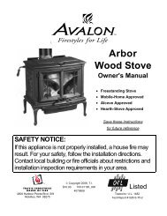
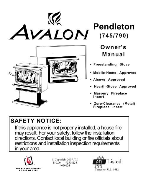
<strong>Pendleton</strong>(<strong>745</strong>/<strong>790</strong>)<strong>Owner's</strong><strong>Manual</strong>• Freestanding Stove• Mobile-Home Approved• Alcove Approved• Hearth-Stove Approved• Masonry FireplaceInsert• Zero-Clearance (Metal)Fireplace InsertSAFETY NOTICE:If this appliance is not properly installed, a house firemay result. For your safety, follow the installationdirections. Contact local building or fire officials aboutrestrictions and installation inspection requirementsin your area.© Copyright 2007, T.I.$10.00 935081334050124ListedTested to: U.L. 1482
2 IntroductionIntroductionWe welcome you as a new owner of an <strong>Avalon</strong> <strong>Pendleton</strong> wood-burning stove. In an <strong>Avalon</strong><strong>Pendleton</strong> you have joined the growing ranks of concerned individuals whose selection of an energysystem reflects both a concern for the environment and aesthetics. The <strong>Avalon</strong> <strong>Pendleton</strong> is one ofthe finest appliances the world over. This manual will explain the installation, operation, andmaintenance of this appliance. Please familiarize yourself with the <strong>Owner's</strong> <strong>Manual</strong> before operatingyour appliance and save the manual for future reference. Included are helpful hints and suggestionswhich will make the installation and operation of your new appliance an easier and more enjoyableexperience. We offer our continual support and guidance to help you achieve the maximum benefitand enjoyment from your appliance.Important InformationNo other <strong>Avalon</strong> <strong>Pendleton</strong> appliance has the sameserial number as yours. The serial number is stampedonto the label on the back of the appliance.This serial number will be needed in case you requireservice of any type.Model: <strong>Avalon</strong> <strong>Pendleton</strong>Serial Number:Purchase Date:Purchased From:Mail your Warranty Card Today,and Save Your Bill of Sale.To receive full warranty coverage, you willneed to show evidence of the date youpurchased your appliance. Do not mailyour Bill of Sale to us.We suggest 1/24/05that you attach your Billof Sale to this page so that you will have allthe information you need in one placeshould the need for service or informationoccur.Travis Industries 93508133 4050124
Table of Contents 3General InformationIntroduction & Important Information ......................2Safety Precautions .............................................4Features & Specifications ....................................6Stove InstallationPlanning The Installation .....................................7Floor Protection Requirements..............................8Stove Placement Requirements ............................9Clearances .......................................................9Chimney Requirements .......................................10Chimney Termination Requirements ......................11Outside Air Requirements ....................................11Alcove Installation Requirements...........................12Mobile Home Requirements .................................13INSTALLATION DIAGRAMSStandard Ceiling with a Factory Built Chimney.....14Cathedral Ceiling with a Factory Built Chimney....14Exterior Factory Built Chimney .........................15Hearth Stove Positive Connection.....................15Hearth Stove Direct Connection .......................16Interior Masonry Chimney ...............................16Insert InstallationPlanning The Installation .....................................17Insert Size Requirements.....................................18Insert Placement Requirements ............................18Hearth Requirements..........................................18Masonry Fireplace Requirements ..........................19Zero Clearance (Metal) Fireplace Requirements.......19Drafting Performance..........................................19Leveling Bolt Installation ......................................19Block-Off Plate Installation ...................................20INSTALLATION DIAGRAMSInsert with Positive Connection.........................21Insert with Direct Connection (Masonry Fireplace)21Insert with Direct Connection (ZC Fireplace) .......22Insert with Face Seal Connection......................22Operating Your ApplianceSafety Notice ....................................................23Before Your First Fire..........................................23Opening the Door...............................................23Starting a Fire ...................................................24Adjusting the Burn Rate.......................................25Ash Removal ....................................................25Optional Blower Operation ...................................26Re-Loading the Stove .........................................26Overnight Burn ..................................................26Normal Operating Sounds....................................26Hints for Burning ................................................27Selecting Wood .................................................27Dry Wood is Key ...........................................27Testing Wood Moisture...................................27Why Dry Wood is Key.....................................27Wood Cutting and Storage ..............................27Troubleshooting.................................................28Maintaining Your ApplianceDaily Maintenance..............................................29Remove Ash ................................................29Clean The Glass ...........................................29Monthly Maintenance..........................................30Door and Glass Inspection ..............................30Check For Creosote Buildup ............................30Yearly Maintenance............................................31Touch Up Paint .............................................31Blower Cleaning............................................31Firebrick and Baffle Inspection .........................31Door Parts ........................................................32Replacing the Glass.......................................32Replacing the Door Gasket..............................32Replacing the Door Handle..............................32Firebox Parts ....................................................33Floor & Side Firebrick Removal & Replacement...33Baffle Removal and Replacement .....................34Air Tube Removal and Replacement .................34WarrantyWarranty ..........................................................35Listing InformationListing Information..............................................36Optional EquipmentStove Legs .......................................................37Pedestal...........................................................37Rear Blower Installation.......................................39Outside Air Boot Installation .................................40Surround Panels ................................................41Front Blower .....................................................43IndexIndex ...............................................................44Travis Industries 93508133 4020509
4 Safety Precautions• The viewing door must beclosed and latched duringoperation.• Never block free airflowthrough the air vents on thisappliance.Gas• Gasoline or other flammableliquids must never be usedto start the fire or "FreshenUp" the fire. Do not store oruse gasoline or otherflammable liquids in thevicinity of this appliance.• This appliance is designedand approved for theburning of cord wood only.Do not attempt to burn anyother type of fuel other thancord wood in this appliance,it will void all warranties andsafety listings.ASHES• Ashes must be disposed ina metal container with atight lid and placed on anon-combustible surfacewell away from the home orstructure.• Do not touch the appliancewhile it is hot and educateall children of the danger ofa high-temperatureappliance. Young childrenshould be supervised whenthey are in the same roomas the appliance.36"• Keep furniture, drapes,curtains, wood, paper, andother combustibles aminimum of 36" away fromthe front of the appliance.• This appliance must beproperly installed to preventthe possibility of a housefire. The instructions mustbe strictly adhered to. Donot use makeshift methodsor compromise in theinstallation.Ok• Contact your local buildingofficials to obtain a permitand information on anyinstallation restrictions orinspection requirements inyour area. Notify yourinsurance company of thisappliance as well.• Inspect the chimneyconnector and chimney atleast twice monthly andclean if necessary.Creosote may build up andcause a house fire.• Do not connect thisappliance to any chimneyserving another appliance.TypeHTClayLiner• This appliance must beconnected to a listed hightemperature (UL 103 HT)residential type chimney oran approved masonrychimney with a standardclay tile, or stainless steelliner.Travis Industries 93508133 4020509
Safety Precautions 5MobileHome• When installed in a mobilehome, this appliance mustbe bolted to the floor, haveoutside air, and not beinstalled in the bedroom(Per H.U.D. requirements).Check with local buildingofficials.• Do not place clothing orother flammable items on ornear this appliance.• Never try to repair or replaceany part of this applianceunless instructions are givenin this manual. All otherwork must be done by atrained technician.• Allow the appliance to coolbefore carrying out anymaintenance or cleaning.• Do not make any changesor modifications to anexisting masonry fireplaceor chimney to install thisappliance.• Do not make any changes tothe appliance to increasecombustion air.• Overfiring the appliance maycause a house fire. If a unitor chimney connector glows,you are overfiring.• Maintain the door and glassseal and keep them in goodcondition.• Avoid placing wood againstthe glass when loading. Donot slam the door or strikethe glass.• Do not use a grate or otherdevice to elevate the fire offof the firebox floor. Burn thefire directly on the bricks.This<strong>Manual</strong>• Do not throw this manualaway. This manual hasimportant operating andmaintenance instructionsthat you will need at a latertime. Always follow theinstructions in this manual.• Travis Industries, Inc.grants no warranty,implied or stated, forthe installation ormaintenance of yourappliance, andassumes noresponsibility of anyconsequentialdamage(s).Travis Industries 93508133 4020509
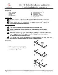
6 Features & SpecificationsInstallation Options:• Freestanding• Freestanding in an Alcove• Freestanding in a Mobile Home• Masonry Fireplace Insert• Factory-Built (Z.C.) Fireplace InsertFeatures:• EPA Phase II Approved• 1.3 Cubic Foot Firebox Volume• Single Operating Control• Accepts Logs Up to 17" Long• Steel Plate Construction (1/4" & 3/16")• Heavy Duty Refractory Firebrick• Optional High-Tech BlowerHeating Specifications:Approximate Maximum Heating Capacity (in square feet)* 600 to 1,200Maximum BTU's per Hour (Cord Wood Calculation) 64,200Overall Efficiency (Oregon Method) 68 %Maximum Burn TimeUp to 8 Hours* Heating capacity will vary depending on the home's floor plan, degree of insulation, and the outsidetemperature. It is also affected by the quality and moisture level of the fuel.Dimensions:Note:Flue Location for <strong>Pendleton</strong>-45Measure side, corner,3-9/16"and back clearancesfrom the stove top.2-1/4"23-3/4" ****17-5/8"(from base)The flue collar protrudes3/4" above the stove top20"*19"Height:Steel Legs (discontinued)..26-1/2"Sculptured or Cast Legs....27-7/8"Pedestal.............................31-3/8"Insert Dimensions:Depth into Fireplace** ........11-5/8"Onto Hearth**** ....................4-3/4"16-3/8"* For inserts, add 3/4" for the flue collar.** ZC (metal) fireplaces require 12-5/8".*** ZC (metal) fireplaces require 25-3/4".**** Does not include hearth protection.Emissions:3.0 Grams Per Hour (EPA Phase II Approved) – Tests conducted by E.E.S.P.C.Travis Industries 93508133 4020509
Stove Installation (for qualified installers only) 7SAFETY NOTICE:Please read this entire manual before you install and use your newroom heater. Failure to follow instructions may result in propertydamage, bodily injury, or even death. Contact local building or fireofficials about restrictions and installation inspection requirementsin your area.Planning The InstallationWe suggest that you have an authorized Travis Industries dealer install your stove. If you install thestove yourself, your authorized dealer should review your plans for installation.Check with local building officials for any permits required for installation of this stove and notify yourinsurance company before proceeding with installation.Preparation for Installation• Check for damage to the exterior of the stove (dents should be reported, scratches can be fixed byapplying touch up paint).• Check the interior of the firebox (replace cracked firebrick and make sure baffle is in place).The stove can be lightened by removing the firebricks and baffle. (pg 33) - replace before operation.Stove Installation ConsiderationsThe table below details the six most common types of installations and the considerations for eachtype. Alternative methods of installation are available if they comply with local building codes.Installation TypeStandard Ceiling with a Factory Built Chimney(Page 14)Cathedral Ceiling with a Factory Built Chimney(Page 14)Exterior Factory Built Chimney(Page 15)Hearth Stove Positive Connection(Page 15)Hearth Stove Direct Connection(Page 16)Interior Masonry Chimney(Page 16)Considerations• Requires ceiling and roof penetration• Provides best draft• Cathedral style chimney support required• Provides best draft• Uses two elbows to route chimney outside• Exterior chimney is hidden from the room• Elbows reduce draft• Optional exterior chase reduces cold air blockage• Utilizes existing masonry or zero clearance (metal) chimney• Provides good draft due to full reline• Easier to clean than direct or horizontal hearth stove• Utilizes existing masonry or zero clearance (metal) chimney• Requires construction of a "block-off plate"• Draft reduced due to elbows & chimney cross section• Utilizes existing masonry chimney (not approved for zeroclearance (metal) fireplaces)Travis Industries 93508133 4020509
8 Stove Installation (for qualified installers only)Floor Protection Requirements• Stove must be placed on the Travis Industries legs or Pedestal.• Must be non-combustible and at least .018" thick (26 gauge)Floor protection must benon-combustible and at least.018" thick (26 gauge).Min. 6”Min. 6”Min. 16”MinimumMinimum 38-3/8"35-3/4"Travis Industries 93508133 4020509
Stove Installation (for qualified installers only) 9Stove Placement RequirementsClearances may be reduced by methods specified in NFPA 211, listed wall shields, pipe shields, orother means approved by local building or fire officials.• Stove must be placed so that no combustibles are within, or can swing within (e.g. drapes, doors),36" of the front of the stove• If the stove is placed in a location where the ceiling height is less than 7', it must follow therequirements in the section "Alcove Installation Requirements"• Must maintain the clearances to combustibles listed below (drywall, furniture, etc.):ClearancesStraight InstallationsCorner InstallationsdefabcNOTE:Measure clearances to the stove top.<strong>Pendleton</strong>-45°<strong>Pendleton</strong>-90°Minimum Clearance(See the illustration above)SinglewallConnectorReducedClearance*SinglewallConnectorReducedClearance*A Sidewall to stove 10" 11" 10" 11"B Backwall to stove 19 1/2" 13" 16 1/2" 8 1/2"C Cornerwall to stove 9 1/2" 7 1/2" 9 1/2" 7 1/2"D Connector to sidewall 19" 19 1/2" 19" 19 1/2"E Connector to backwall 17 1/2"** 9"** 17 1/4" 8 3/4"F Connector to cornerwall 16"** 11"** 17 1/2" 15"* Reduced clearance installations require one of the chimneys and connectors listed below:• DURAVENT model DVL with DURATEC chimney• DURAVENT model DVL with DURA-PLUS chimney• AMERI-TEC model DCC with model HS chimney• SECURITY model DL with SECURITY model ASHT or S2100 chimney• METAL-FAB model DW with TG chimney• GSW Double Wall Chimney Connector with Super Chimney Twenty-One• SELKIRK METALBESTOS model DS connector with model SSII chimney• I.C.C. Excel (2100-2 Can.) (103-HT USA) chimney with HP connector• Standard Masonry Chimney with any one of the above listed connectors** These are minimum clearances, not installation dimensions. Connector position will vary dependingupon brand. First establish the stove clearances, install the 45° connector to the stove, then determine the position ofthe connector.NOTE :NOTE :Standard residential installations with reduced clearance connector may use the clearance determined by themanufacturer of the connector for the connector to wall clearance or the clearance listed in this manual.Offsets must be used to maintain the stove to wall clearance.Reduced clearance connectors may not connect to the flue collar – order an appliance adapter for theconnector being used.Travis Industries 93508133 4020509
10 Stove Installation (for qualified installers only)Chimney Requirements• DO NOT CONNECT THIS UNIT TO A CHIMNEY FLUE SERVING ANOTHERAPPLIANCE.• Chimney connector must be a minimum 24 MSG black or 26 MSG blued steel (6" diameter).Chimney must be used from the first floor or wall penetration to the chimney cap.• Use 6" diameter type UL 103 HT chimney from one manufacturer (do not mix brands) or codeapproved masonry chimney with a flue liner.• Chimney connector and chimney must be fastened to the stove and each adjoining section.• Follow the chimney manufacturer's clearances and requirements.• Use the chimney manufacturer's fire stops, attic guards, roof supports, and flashings when passingthrough a ceiling or thimble when passing through a combustible wall.• No more than 180 o of elbows (two 90 o elbows, or two 45 o & one 90 o elbow, etc.).NOTE: Additional elbows may be allowed if draft is sufficient. Whenever elbows are used the draft isadversely affected. Additional chimney height may be required to boost draft.Chimney Cap(See the section"Chimney TerminationRequirements" formore details)Factory BuiltChimneySectionsFloor PenetrationEquipment (AtticRadiation Shield withChimney Support)ReducecedClearanceChimneyConnectorSectionsFloorProtection }}Roof Penetration Equipment(Roof Radiation Shield,}Flashing, Storm Collar)Minimum Air Space toCombustibles (SeeChimney Manufacturer'sInstructions - usually 2")Minimum System 15'Maximum System 33'Standard residential installations withreduced clearance connector may use theclearance determined by the manufacturerof the connector for the connector to wallclearance or the clearance listed in thismanual.Mobile home installations must use thethe reduced clearance connectorclearances listed in this manual under“Additional Requirements for Mobile HomeInstallations”.DraftingPerformanceStove Clearance(as outlined in this manual)This appliance relies upon natural draft to operate. External forces, such as wind,barometric pressure, topography, or factors of the home (negative pressure from exhaustfans, chimneys, air infiltration, etc.), may adversely affect draft. Travis Industries can not beresponsible for external forces leading to less than optimal performance.• Standard residential installations may use single-wall connector (Mobile-Homes may not)• Standard residential installations with reduced clearance connector may use the clearancedetermined by the manufacturer of the connector for the connector to wall clearance or the clearancelisted in this manual. Offsets must be used to maintain the stove to wall clearance. Mobile homesmust use the clearances listed in this manual under "Additional Requirements for Mobile HomeInstallations".Travis Industries 93508133 4020509
Stove Installation (for qualified installers only) 11Chimney Termination Requirements• Must have an approved cap (to prevent water from entering)• Must not be located where it will become plugged by snow or other material• Must terminate at least 3' above the roof and at least 2' above any portion of the roof within 10'Slanted RoofsFlat RoofsChimney mustextend 3'above the roofChimney mustextend 3'above the roofOutside Air RequirementsChimney must extend 2'above any portion of the roofwithin 10' of the chimney• Required for mobile homes & in certain localities (check with building officials)• Must not be drawn from an enclosed space (garage, unventilated crawl space)• Requires the optional outside air boot (for legs) or pedestal.Chimney must extend 2'above any portion of the roofwithin 10' of the chimneyWhen using outside air, find a location where the chimney andoutside air hole do not interfere with structural members of the home.Pedestal (with insulation)directs air to the stove.A hole must be cutthrough the floorprotection andfloor and therodent screennailed in placehere (see theoptional equipmentinstructions forexact sizes)OutsideAir BootOptional Air Duct (must not belonger than 15' and at least 16square inches in cross section)Air may be drawn from a ventilatedcrawl space or use an air duct.Outside air entrance must be placed soit does not become blocked by snow.Travis Industries 93508133 4020509
12 Stove Installation (for qualified installers only)Alcove Installation RequirementsWhenever the stove is placed in a location where the ceiling height is less than 7' tall, it is consideredan alcove installation. Because of the reduced height, the special installation requirements listedbelow must be met.• Chimney connector and chimney must be one of the following types:• DURAVENT model DVL with DURATEC chimney• DURAVENT model DVL with DURA-PLUS chimney• AMERI-TEC model DCC with model HS chimney• SECURITY model DL with SECURITY model ASHT or S2100 chimney• METAL-FAB model DW with TG chimney• GSW Double Wall Chimney Connector with Super Chimney Twenty-One• SELKIRK METALBESTOS model DS connector with model SSII chimney• I.C.C. Excel (2100-2 Can.) (103-HT USA) chimney with HP connector• Standard Masonry Chimney with any one of the above listed connectors<strong>Pendleton</strong>-45°<strong>Pendleton</strong>-90°Minimum Clearance(See the illustration below)CombustibleAlcoveNon-CombustibleAlcoveCombustibleAlcoveNon-CombustibleAlcoveA Sidewall to stove 11" 6" 11" 6"B Backwall to stove 13" 5" 8 1/2" 2"D Connector to sidewall 19 1/2" 14 1/2 19 1/2" 14 1/2"E Connector to backwall 9"* 2 1/2"* 8 3/4" 2 1/4"G Maximum depth of alcove 48" 48" 48" 48"H Minimum width of alcove 45 3/4" 35 3/4" 45 3/4" 35 3/4"J Minimum height of alcove 84" 6" above stove top 84" 6" above stove top• Alcoves are classified as combustible or non-combustible. Non-combustible alcoves must havewalls and a ceiling that are 3 1/2" thick of a non-combustible material (brick, stone, or concrete).This non-combustible material must be spaced and ventilated at least 1" off of all combustiblematerials (walls, ceiling, etc.) to allow air to move around the non-combustible walls and ceiling.All other alcoves are considered combustible. The clearances below must be met:Non-combustible alcoveconstruction (on wallsand ceiling) - see theexplanation above.deVentilatedair space1" Min.Combustiblematerials3 1/2" thick noncombustiblematerialNon-combustiblereinforcerjabhgTravis Industries 93508133 4020509
Stove Installation (for qualified installers only) 13Mobile Home Requirements• Outside air must be installed - see "Outside Air Requirements" on page 11• Chimney connector and chimney must be one of the following types:• DURAVENT model DVL with DURATEC chimney• DURAVENT model DVL with DURA-PLUS chimney• AMERI-TEC model DCC with model HS chimney• SECURITY model DL with SECURITY model ASHT or S2100 chimney• METAL-FAB model DW with TG chimney• GSW Double Wall Chimney Connector with Super Chimney Twenty-One• SELKIRK METALBESTOS model DS connector with model SSII chimney• I.C.C. Excel (2100-2 Can.) (103-HT USA) chimney with HP connector• Standard Masonry Chimney with any one of the above listed connectorsNOTE: Reduced clearance connectors may not connect to the flue collar – order an applianceadapter for the connector being used.• Stove placement must maintain the following clearances to combustibles (drywall, furniture, etc.)Minimum Clearance <strong>745</strong> Reduced(See the illustration below)Clearance<strong>790</strong> ReducedClearanceConnectorConnectorA Sidewall to stove 11" 11"B Backwall to stove 13" 8 1/2"C Cornerwall to stove 7 1/2" 7 1/2"D Connector to sidewall 19 1/2" 19 1/2"E Connector to backwall 9"* 8 3/4"F Connector to cornerwall 11"* 15"* These are minimum clearances, not installation dimensions. Connector position will varydepending upon brand. First establish the stove clearances, install the 45° connector to the stove, thendetermine the position of the connector.Straight InstallationsCorner InstallationsdefabcNOTE:Measure clearances to the stove top.• If using offsets, use the connector clearance listed to theright, not the connector manufacturer'sclearance.• The appliance must be secured to the floor (consult yourbuilding official). Secure the outside air boot to the floorand stove to insure the stove does not dislocate.• Mobile home installations require a spark arrester at thechimney termination.• The appliance must be grounded to the chassis of themobile home (consult your building official).WARNING: DO NOT INSTALL IN SLEEPING ROOM.CAUTION:THE STRUCTURAL INTEGRITY OF THEMOBILE HOME FLOOR, WALL, ANDCEILING/ROOF MUST BE MAINTAINED.12-1/4”Min.Minimum ConnectorClearance(as outlined above)Minimum StoveClearance(as outlined above)Travis Industries 93508133 4020509
14 Stove Installation (for qualified installers only)Chimney Cap (See the section "ChimneyTermination Requirements"for more details) StandardCeiling witha FactoryBuiltChimneyChimney SectionsInsulationFollow the chimneymanufacturer's instructionsand clearances for floorpenetrations. A ceilingsupport is required, an atticinsulation shield is requiredwhere insulation is present.}} Follow the chimneymanufacturer's instructionsand clearances for roofpenetrations. A storm collarand flashing are required(some require a radiationshield).Minimum Air Space toCombustibles (SeeChimney Manufacturer'sInstructions - usually 2")Chimney Connector SectionsMinimum 15'Maximum 33'Floor Protection(See the section "FloorProtection Requirements"for more details)Stove Clearances(See the section "StovePlacement Requirements"for more details)CathedralCeiling witha FactoryBuiltChimneyChimney Cap(See the section "ChimneyTermination Requirements"for more details)Chimney SectionsMinimum Air Space toCombustibles (See ChimneyManufacturer's Instructions -usually 2")ChimneyConnectorSections}Follow the chimneymanufacturer's instructionsand clearances for roofpenetrations. A stormcollar, flashing, andcathedral-style chimneysupport are required(some require a radiationshield).Minimum 15'Maximum 33'Floor Protection(See the section "FloorProtection Requirements"for more details)Stove Clearances(See the section "StovePlacement Requirements"for more details)Travis Industries 93508133 4020509
}Stove Installation (for qualified installers only) 15ExteriorFactoryBuiltChimneyNOTE:Exterior chimneysare subject togreater moistureand creosoteaccumulation dueto the lowertemperatures. Aninsulated chasewill reduce theseaccumulations(the properclearances to thechimney must bemaintained).HearthStovePositiveConnectionNOTE:Most factory-builtchimneymanufacturersmake stainlesssteel chimneyliners, eitherflexible or rigid.This provides awide variety ofinstallationoptions. Makesure to follow themanufacturer'sinstructions forinstallation andsupport.Chimney Cap(See the section "ChimneyTermination Requirements"for more details)Chimney SectionsMinimum Air Space toCombustibles (SeeChimney Manufacturer'sInstructions - usually 2")Min. 18"clearance toceilingChimney ConnectorSectionsFloor Protection(See "FloorProtectionRequirements"for details)Wall BandsandSupportsNOTE: The entire fireplace andchimney must be clean, undamaged,and meet all local building codes(UBC, etc.). Damage must berepaired prior to installation. Thechimney must be 15' to 33' tall.CombustibleMantleFloor Protection(See the section"Floor ProtectionRequirements"for more details)Min. 18"}Minimum 15'Maximum 33'Stove Clearances(See the section "StovePlacement Requirements"for more details)Follow the chimneymanufacturer'sinstructions andclearances for roofpenetrations. A stormcollar and flashing arerequired (somerequire a radiationshield).Insulated Tee(with cleanout )Follow the chimneymanufacturer'sinstructions andclearances for wallpenetrations. Awall radiation shield(thimble) isrequired.OptionalinsulatedchaseCap and flashingprevents water fromenteringThe liner must bestainless steel connectoror flexible vent. Followthe liner manufacturer'sinstructions for installationand support.Airtight InsulatedClean-OutRemove damperor wire it openSee the section"Stove PlacementRequirements" forminimum clearancesrequired.Travis Industries 93508133 4020509
16 Stove Installation (for qualified installers only)HearthStoveDirectConnectionNOTE:Directconnectionsrequire installationof an airtight, noncombustibleblock-off plate ordamper adapter.NOTE: The chimney must have a claytile liner. If it does not, the installationmust use a positive connection (fullreline). The entire fireplace andchimney must be clean, undamaged,and meet all local building codes (UBC,etc.). Damage must be repaired priorto installation. The chimney must be15' to 33' tall.Max. 8”Combustible MantleFloor Protection(See the section "FloorProtection Requirements"for more details)Min. 18"ClayLinerStainless steelchimney connectormust Extend 1' pastthe block-off plate orto the flue linerAirtightInsulatedClean-OutRemove damperor wire it openBlock-off plate ordamper adapterSee the section"Stove PlacementRequirements" forminimum clearancesrequired.Interior orExteriorMasonryChimneyNOTE:This type ofinstallationrequires a UBCapprovedmasonryconnector or afactory built (U.L.Listed) wallthimble.NOTE: The chimney must have aclay tile liner. If it does not, theinstallation must use a positiveconnection (full reline). Theentire fireplace and chimney mustbe clean, undamaged, and meetall local building codes (UBC,etc.). Damage must be repairedprior to installation. The chimneymust be 15' to 33' tall.See the section "StovePlacement Requirements" forminimum clearances required.Chimney connector sectionsMin. 18"clearanceto ceilingClay LinerThis type ofinstallation requiresa UBC approvedmasonry connectoror a factory built(U.L. Listed) wallthimble.See the section"Floor ProtectionRequirements"Make sure theclean-out seals inplace.Travis Industries 93508133 4020509
Insert Installation (for qualified installers only) 17SAFETY NOTICE:Please read this entire manual before you install and use your newroom heater. Failure to follow instructions may result in propertydamage, bodily injury, or even death. Contact local building or fireofficials about restrictions and installation inspection requirementsin your area.Planning The InstallationWe suggest that you have an authorized Travis Industries dealer install your stove. If you install thestove yourself, your authorized dealer should review your plans for installation.Check with local building officials for any permits required for installation of this stove and notify yourinsurance company before proceeding with installation.Preparation for Installation• Check for damage to the exterior of the inserts (dents should be reported, scratches can be fixed byapplying touch up paint).• Check the interior of the firebox (replace cracked firebrick and make sure baffle is in place).The stove can be lightened by removing the firebricks and baffle. (pg 26) - replace before operation.Insert Installation Considerations• This insert is approved for installation into an existing masonry or zero clearance (metal) fireplace.Depending upon your installation concerns, several options are yours to provide the most desirableinstallation. The sections that follow detail the requirements that must be met for a safe installation.To further help installation, the most common types of installations are explained in table below. Priorto installing your insert make a detailed plan with dimensions to double-check them against all of therequirements listed.Installation TypeInsert with Positive Flue (Full Reline)(Page 21)Insert with Direct Connect Flue(Page 21 and 22)Insert with Face Seal Connection(Page 22)Considerations• Utilizes existing masonry or zero clearance fireplace• Provides best draft• Easiest to clean• Utilizes existing masonry or zero clearance fireplace• Provides good draft• Requires fireplace block-off plate - see page 18• Utilizes existing masonry fireplaces with cross sectionof 28" to 144" (not approved for zeroclearance fireplaces)• Provides okay draft• Easiest to install• Requires the optional surround panels and insulation(see "Surround Panels" on page 42).Surround Panels• The insert must be installed with surround panels (see page 42).Travis Industries 93508133 4020509
18 Insert Installation (for qualified installers only)Insert Size Requirements (see Illustration below)jhiCombustible MantelNon-Combustible FacingbacNon-Combustible HearthdegfInsert Placement RequirementsMinimumFireplace SizeabcdefghijHeight (front)Height (rear)Width (front)Width (rear)DepthHearth Depth*Hearth WidthFacing WidthFacing HeightMantel HeightMasonryFireplace21 1/2"21 1/2"23 3/4"23 3/4"11 3/8"20 3/4"39 3/4"41 3/4"39"41"Z.C. (Metal)Fireplace21 1/2"21 1/2"25 3/4"25 3/4"12 3/8"20 3/4"39 3/4"47 3/4"31"43"* This is the distance the insert protrudes fromthe fireplace opening plus the required 16" ofhearth extension.• The insert must be placed so that no combustibles are within, or can swing within (e.g. drapes,doors), 36" of the front of the insert• Insert and hearth must be installed on a level, secure floor• The minimum clearances, facing, and hearth requirements in the illustration below must be met(follow the clearances for the type of fireplace being used - either masonry or zero-clearance).Minimum ClearancesnmklpqxoSideWallNon-CombustibleHearthCombustible MantelCombustible Top FacingHearth RequirementsFacingklmnopqxSidewall to InsertSide FacingTop Facingw. Mantel ShieldMantel to Insertw. Mantel ShieldHearth (Front)*Hearth (Side)Front of InsertExtension onto HearthMasonryFireplace10"9"20"14 1/2"22"16 1/2"16"8"36"4 3/4"* Does not include the distance the insertextends onto the hearth (dimension "x").ZC (Metal)Fireplace30"12"12"n/a24"n/a16"8"36"4 3/4"• Must extend 16" in front of the insert and 8" on both sides• Must be non-combustible 1/4" thick insulating board with a thermal conductivity of K = 0.72Travis Industries 93508133 4020509
Insert Installation (for qualified installers only) 19Masonry Fireplace Requirements• Chimney must have a clay tile liner or a stainless steel liner (positive connection)• Entire fireplace, including chimney, must be clean and undamaged. Any damage must be repairedprior to installation of the insert• Chimney height: 15' minimum; 33' maximum.• Entire fireplace, including chimney, must meet local building requirementsZero-Clearance (Metal) Fireplace Requirements:• Must utilize a positive (full reline) or direct connection (block-off plate)• Must be manufactured by one of the following manufacturers:• Marco • Majestic • Heatilator • Preway • Tempco • Superior• Heat N Glo • Lennox • Martin • Monesson• Entire fireplace, including chimney, must be clean and undamaged. Any damage must be repairedprior to installation of the insert• Entire fireplace, including chimney, must meet local building requirements• Chimney height: 15' minimum; 33' maximum. Minimumcross section: 28.65 square inchesH• The damper ("A") and grate ("B") must be removed (seethe illustration to the right)FCA• The smoke shelf ("C"), internal baffles ("D"), screen ("E"),and metal or glass doors ("F") may be removed (ifDapplicable)EI• The masonry lining ("G"), insulation ("H"), and anystructured rigid frame members (metal sides, floor, doorBframe, face of the fireplace, etc. – "I") may not beGremoved or alteredDrafting PerformanceThis appliance relies upon natural draft to operate. External forces, such as wind, barometricpressure, topography, or factors of the home (negative pressure from exhaust fans, chimneys, airinfiltration, etc.), may adversely affect draft. Travis Industries can not be responsible for externalforces leading to less than optimal performance.Leveling Bolt InstallationTwo leveling bolts are included to level the insert if the fireplace has a stepped-up hearth. To install,raise the rear of the insert up and insert the leveling bolts into the holes in the rear corners of theinsert. Adjust the bolts until they extend the same height as the hearth steps up. After the insert isinstalled, fine-tune the leveling bolts to level the insert (see the illustration).This distance is thehearth step-up. Theleveling bolts shouldstick out this far from thebase of the insert.HearthFireplaceThe leveling bolts gointo the holes at therear corners of theinsert.Travis Industries 93508133 4090313
20 Insert Installation (for qualified installers only)Block-Off Plate InstallationWhenever this appliance is installed with a direct connection a block-off plate, or other noncombustibleseal-off device (e.g. damper adapter), will need to be installed. This device is used toseal the chimney, insuring no smoke enters the home and providing the chimney system with a sealto promote draft. The directions below detail the steps for construction and installation of a block-offplate.1. Determine a location for the block-off plate at the top of the firebox below the damper area (makeit high enough to allow installation of the connection pipe). The location should be level and in anarea where it can be mounted easily. Measure the width at the rear ("A") and front ("B") of thefirebox at the height where the block-off plate will be installed (see the illustration below). Thenmeasure the depth of the location where the block-off plate will be installed ("C").NOTE: Most masonry fireplaces have square fireboxes while certain zero-clearance (metal)fireplaces often have domed firebox tops. This makes zero-clearance block-off plates moredifficult to install. To simplify the procedure, insulation may be used to seal the rounded edges.2. Make a cardboard template of the measurements, but add a 2" flange to each side. This flangewill be used to mount the block-off plate to the inside of the firebox. Bend the flanges downwardson the template and place it inside the fireplace. If the template fits correctly in its plannedlocation, go to the next step. If it does not, make a new template with the appropriate correctionsuntil it fits correctly.3. With the template in place, mark the location that is centered in the fireplace and 9 1/4" back fromthe fireplace opening. This location approximates the center of the flue when the insert is in place(a slight offset may occur based upon insert and block-off plate placement). Remove thetemplate and cut a 6 1/4" diameter hole centered on this mark.4. Make the block-off plate of 24 gage or thicker steel to match the template. Drill two holes in eachflange for mounting the plate.5. Mount the block-off plate using masonry screws.NOTE: Use sheet metal screws on zero-clearance (metal) fireplaces (screws need only be longenough to penetrate the first layer of metal).6. Insulate the block-off plate using high-temperature fiberglass insulation (Kaowool® or equivalent)and furnace cement (allow the cement to dry for at least 24 hours before burning).7. After placing the appliance and installing the pipe through the block-off plate, use hightemperaturefiberglass insulation and furnace cement to seal any cracks between the pipe andblock-off plate.The center ofthe flue is 9 1/4"back from thefireplaceopening.BCFireboxDamper ABlock-Off Plate Template2" Flanges(for attachingthe block-offplate)Measurement"A"Measurement "B"The center of the flue is 9 1/4" back from thefireplace opening (6 1/4" in diameter).Measurement"C"Travis Industries 93508133 4020509
Insert Installation (for qualified installers only) 21Insert withPositiveConnectionNOTE:Most factory-builtchimneymanufacturersmake stainlesssteel chimneyliners, eitherflexible or rigid.This provides awide variety ofinstallationoptions. Makesure to follow themanufacturer'sinstructions forinstallation andsupport.Insert withDirectConnection(MasonryFireplace)NOTE:Directconnectionsrequire installationof an airtightblock-off plate ordamper adapter(see "Block-offPlate Installation"on page 20).NOTE: This installation may beused with a masonry or zeroclearance fireplace. Therequirements in the section"Masonry Fireplace Requirements"or "Zero Clearance FireplaaceRequirements" must be fulfilledprior to installation.Combustible MantleSurround PanelsSee the section "InsertPlacement Requirements" forminimum clearances andhearth required.Install a non-combustiblecover plate to prevent waterfrom entering the chimneyNOTE: This installation may beused with a masonry or zeroclearance fireplace. Thisillustration depicts a masonryinsert, all requirements in thesection "Masonry FireplaceRequirements" must be fulfilledprior to installation.Combustible MantleSurround PanelsSee the section"Insert PlacementRequirements" forminimum clearancesand hearth required.Travis Industries 93508133 4020509Cap (prevents waterfrom entering)Flue LinerThe liner must bestainless steelconnector or flexiblevent. Follow the linermanufacturer'sinsturctions forinstallation andsupport.Airtight InsulatedClean-OutRemovedamperor wire itopenRemove damperor wire it openFlueLinerStainless steelchimney connectormust Extend 1' pastthe block-off plate orto the flue linerAirtightInsulatedClean-OutBlock-off plate ordamper adapter
22 Insert Installation (for qualified installers only)Insert withDirectConnection(Z.C.Fireplace)NOTE:Directconnectionsrequire installationof an airtightblock-off plate ordamper adapter(see "Block-offPlate Installation"on page 20).NOTE: This installation may beused with a masonry or zeroclearance fireplace. Thisillustration depicts a zeroclearance insert, all requirementsin the section "Zero ClearanceFireplace Requirements" must befulfilled prior to installation.Combustible MantleSurround PanelsSee the section"Insert PlacementRequirements" forminimum clearancesand hearth required.Stainless steelchimney connectormust Extend 1' pastthe block-off plate.Damper mustbe removedBlock-off plate ordamper adapterZ.C. (Metal) fireboxOptionalTelescoping LegsNo modification to the fireboxof the z.c. fireplace is allowed.Insert withFace SealConnectionNOTE:Face sealconnectionsrequire installationof the surroundpanels andinsulation (see the"Surround PanelInstallation" onpage 42).NOTE: This installation may beused with a masonry fireplaceonly. The requirements in thesection "Masonry FireplaceRequirements" must be fulfilledprior to installation.FlueLinerCombustible MantleSurround Panels withinsulation (see "SurroundPanels" installationinstructions in the back ofthe manual)See the section "InsertPlacement Requirements"for minimum clearancesand hearth required.NOTE: It isrecommended yourchimney have aminimum 28 and amaximum of 144square inch crosssectionalarea to use aface seal connection,otherwise yourchimney maynot havesufficient draw for thefireplace insert tooperate correctly.Airtight InsulatedClean-OutRemove damperor wire it openTravis Industries 93508133 4020509
Safety Notice:Operating Your Appliance 23If this appliance is not properly installed, a house fire may result. For your safety, follow the installationdirections. Contact local building or fire officials about restrictions and installation inspectionrequirements in your area.Read and follow all of the warnings on pages 4 and 5 of this manual.Before Your First FireVerify the InstallationBefore starting the stove, verify that the stove is properly installed and all of the requirements in thismanual have been followed.Keep all flammable materials 36" away from the front of the stove (drapes, furniture, clothing, etc.).Curing the PaintThis heater uses a heat-activated paint that will emit some fumeswhile starting the first fire. Open doors and windows to the roomto vent these fumes. This typically lasts two to four hours. Youmay also notice oil burning off of the interior of the heater. Thisrust-stopping agent will soon dissipate.Door Gasket - The door gasket might adhere to the paint onthe front of the heater. Leave the door slightly ajar for the first fireand be careful when opening the door after the first fire.Over-Firing the Stove2 to 4 hoursThis stove was designed to operate at a high temperature. But due to differences in ventconfiguration, fuel, and draft, this appliance can be operated at an excessive temperature. If thestove top or other area starts to glow red, you are over-firing the stove. Shut the air control down tolow and allow the stove to cool before proceeding.Opening the DoorTurn the handle clockwise to un-latch.Swing the door open.The door becomes hot during use. Use a glove to open the door if the handle is hot.To prevent smoke from entering the room, open the door a small amount and let air enter the firebox.This stabilizes the air flow before opening the door completely.Travis Industries 93508133 4020509
24 Operating Your ApplianceStarting a FireSince the dawn of time man has debated the best way to start a fire. Some use the boy-scout "teepee",some prefer the "tic-tac-toe" stack. Either way, review the hints and warnings below to ensureproper fire starting.• Make sure the air control is pushed in. If additional air is needed, open the doors 1/4" during the firstfive minutes of start-up.Never use gasoline, gasoline-type lantern fuel, kerosene, charcoal lighter fluid, or similar liquids to startor "freshen up" a fire in this stove. Keep all such liquids well away from the stove while it is in use.If using a firestarter, use only products specifically designed for stoves - follow the manufacturer'sinstructions carefully.If the smoke does not pass up the chimney, ball up one sheet of newspaper, place it in the center of thegrate and light it. This should start the chimney drafting (this eliminates "cold air blockage").Use plenty of kindling to ensure the stove reaches a proper temperature. Once the kindling is burningrapidly, place a few larger pieces of wood onto the fire.Travis Industries 93508133 4020509
Operating Your Appliance 25Adjusting the Burn RateUse the air control slider to control the burn rate of the stove. See the illustration below for details.Use the air control tochange the burn rate.Low Burn(air control closed)High Burn(air control open)Approximate AirControl Settings: Overnight Burn .............. Fully down to 1/64" open (up)Medium Burn.................. 1/64" to 1/32" openMedium High Burn ........ 1/32" to 1/16" openHigh Burn........................ 1/16" to fully open (up)The air control becomes hot during operation - use gloves or a tool to prevent burns.The air control may take several minutes to influence the burn rate. When making adjustments, you maywish to let the stove burn for 10 minutes to gauge performance.Ash RemovalASHESAshes should be placed in a metal container with a tight fitting lid. The closed container of ashesshould be placed on a noncombustible floor or on the ground, away from all combustiblematerials, pending final disposal. If the ashes are disposed of by burial in soil or otherwise locallydispersed, they should be retained in the closed container until all cinders have thoroughlycooled.Travis Industries 93508133 4020509
26 Operating Your ApplianceOptional Blower OperationThe blower will turn on once the stove is up to temperature. This is typically 15 to 30 minutes afterstarting the fire. Follow the directions below to alter the blower speed.OFFTurn the dial all the way counterclockwiseuntil it clicks off.LOBLOWERCONTROLThe high position is all the way counterclockwise,without clicking off.LOOFF HIHIGHBLOWERCONTROLTurn the dial all theway clockwise.LOLOWOFF HIOFF HIBLOWERCONTROLThe blower may be used to affect heat output (i.e.: to reduce heat output, turn the blower down).Route the power cord in a location where it will not come in contact with the appliance or become hot.Re-Loading the StoveFollow the directions below to minimize smoke spillage while re-loading the stove.1 Push the air control all the way in (high burn).2 Open the door slightly. Let the airflow inside the firebox to stabilize before opening the doors fully.3 Load wood onto the fire.Overnight BurnThis stove is large enough to accommodate burn times up to eight hours. Follow the steps below toachieve an overnight burn.1 Move the air control to high burn and let the stove become hot (burn for approximately 15 minutes).2 Load as much wood as possible. Use large pieces if possible.3 Let the stove burn on high for 15 minutes to keep the stove hot, then turn the air control to low.4 In the morning the stove should still be hot, with embers in the coal bed. Stir the coals and load smallpieces of wood to re-ignite the fire, if desired.Differences if chimney height and draft may lower overall burn times.Normal Operating SoundsCreaks and Clicks:The 3/16" and 1/4" steel may creak or click when thestove heats up and cools down - this is normal.Blower Sounds:The blower will make a slight "humm" as itpushes air through the stove.Hint:Make sure the leveling bolts on legs are extended -preventing the hearth from amplifying any vibrations.Travis Industries 93508133 4020509
Operating Your Appliance 27Hints for Burning• Get the appliance hot before adjusting to low burn• Use smaller pieces of wood during start-up and high burns to increase temperature• Use larger pieces of wood for overnight or sustained burns• Stack the wood tightly together to establish a longer burn• Leave a bed of ashes (1/2" deep) to allow for longer burns• Be considerate of neighbors & the environment: burn dry wood only• Burn small, intense fires instead of large, slow burning fires when possible• Learn your appliance's operating characteristics to obtain optimum performanceSelecting WoodDry Wood is KeyDry wood burns hot, emitsless smoke and createsless creosote.WetWoodLeadsToDryWoodLeadsToTesting WoodMoistureSplit wood stored in a dryarea will be fully dry withina year. This insures drywood. If purchasing woodfor immediate use, test thewood with a moisturemeter. Some experiencedwood burners can measurewood moisture by knockingpieces together andlistening for a clear "knock"and not a "thud".LessHeatLeadsToMore Smokeand CreostoeMoreHeatLeadsToLess Smokeand CreostoeWhy Dry Wood is KeyWet wood, when burned, must release water stored within the wood. This cools the fire, createscreosote, and hampers a complete burn. Ask any experienced wood burner and he or she will agree:dry wood is crucial to good performance.Wood Cutting and StorageCut wood to length andchop into quarters.Store the wood off the ground in acovered area. Allow for airflowaround the wood to dry the wood.Air FlowAir FlowAir FlowTravis Industries 93508133 4020509
28 Operating Your ApplianceTroubleshootingProblemPossible CauseSmoke Enters RoomDuring Start-UpKindling Does Not Start -Fire SmoldersSmoke Enters RoomWhile Re-LoadingStove Does Not Burn HotEnough• Cold Air Blockage - burn a piece of newspaper toestablish a draft.• Close the doors - if the flame is not getting enough air,first make sure the air control is open (all the way in).If additional air is needed, a small crack in the door isall that is needed.• Cold Air Blockage - burn a piece of newspaper toestablish a draft.• Not enough starter paper - use additional newspaper ifnecessary.• Not enough air - first make sure the air control is open(all the way in). If additional air is needed, a smallcrack in the door is all that is needed.• Let the air stabilize before fully opening the door. Pushthe air control in before opening the door. Then openthe door approximately 1 inch. Let air go into thefirebox for a few seconds. Once the smoke appears tobe flowing up the chimney consistently, open the door.• Insufficient Draft - Chimney height and outsideconditions can negatively affect draft. In these cases asmall amount of smoke may enter the home. Addingmore pipe or a draft-inducing cap may help.• Wood is Wet - see the section "Selecting Wood" onpage 27 for details on wood.• Insufficient Draft - Chimney height and outsideconditions can negatively affect draft. In these casesthe fire may burn slowly. Adding more pipe or a draftinducingcap may help.• Air Control is Not Wide Open - Make sure the aircontrol is all the way in. Slide the control back andforth to insure the control is not stuck.Blower Does Not Run • Stove is Not Up to Temperature - This is normal. Theblower will come on when the stove is hot - usually 15to 30 minutes.• Electricity is Cut to the Blower - Check the householdbreaker or fuse to make sure it is operable.Stove Does Not BurnLong Enough• This appliance burns for up to 8 hours. Dependingupon wood, draft, and other factors, the burn time maybe shorter. Make sure the doors are sealing and notallowing air into the firebox - See the section "Door andGlass Inspection" on page 30 for details.• Check the ash bed for coals. Often, coals are stillglowing under a slight bed of flyash. By raking theseinto a pile you can re-start your stove quickly.Travis Industries 93508133 4020509
Maintaining Your Appliance 29Failure to properly maintain and inspect your appliance may reduce the performance and life of theappliance, void your warranty, and create a fire hazard.Daily Maintenance (while stove is in use)Remove Ash (if necessary)Ash removal is not required once it builds up. 1/2" to 1" of ash may be desirable because it slows theburn rate. Generally, remove ash once it has built up over 1". Follow the directions below to removeash.1 Let the stove cool completely (at least two hours after the last coal has extinguished).2 Place a cloth or cardboard protector over the hearth to catch ash and protect againstscratching.3 Open the doors and scoop the ash into a metal container with a tight fitting lid. TheASHESclosed container of ashes should be placed on a noncombustible floor or on the ground,away from all combustible materials, pending final disposal.Improperly disposed ashes lead to fires. Hot ashes placed in cardboard boxes, dumped in back yards,or stored in garages, are recipes for disaster.Wood-burning stoves are inherently dirty. During cleaning have a vacuum ready to catch spilled ash(make sure ash is entirely extinguished).There are vacuum cleaners specifically made to remove ash (even if the ash is warm). Contact yourdealer for details.Clean the Glass (if necessary)This appliance has an airwash to keep the glass clean. However, burning un-seasoned wood orburning on lower burn rates leads to dirtier glass (especially on the sides). Clean the glass byfollowing the directions below.Allow the stove to fully cool. Apply glasscleaner or soapy water to the inside ofthe glass. Wipe with newspaper or apaper towel.For Stubborn Creosote:Dip newspaper or a paper towel in coolashes and wipe it on the glass. The ashacts as a light abrasive.The glass will develop a very slight haze over time. This is normal and will not affect viewing of the fire.Travis Industries 93508133 4020509
30 Maintaining Your ApplianceMonthly Maintenance (while appliance is in use)Make sure the appliance has fully cooled prior to conducting service.Door and Glass InspectionThe door must form an air-tight seal to the firebox for the stove to work correctly. Inspect the doorgasket to make sure it forms an air-tight seal to the firebox.The door can be lifted off the hinges if extensive repairs are conducted.High-Temperature anti-siezemay be used on the doorhinges to eliminate squeaks.Use wood stove gasketcement to re-adhereloose gasket.If the glass is damaged, replaceit - see “Replacement Parts” fordetails.Severely frayed or thread-baregasket should be replaced.The door latch should pull the door against the face of the stove (but not so tight as to not allow fullhandle rotation). If the latch requires adjustment, follow the directions below.Side View of Door HandleExploded ViewDoor CamDoorHandleWashersDoor FrameUse a 9/16"socket wrench toremove this nut.Door CamAdjustment:To tighten, removea washer from theinside of the doorframe. To loosen,place an additionalwashers on theinside of the doorframe or loosenthe nut 1/2 turn.Creosote - Formation and Need for RemovalWhen wood is burned slowly, it produces tar and other organic vapors, which combine with expelledmoisture to form creosote. The creosote vapors condense in the relatively cool chimney flue of a slowburningfire. As a result, creosote residue accumulates on the flue lining. When ignited, this creosotemakes an extremely hot fire. The chimney and chimney connector should be inspected at least onceevery two months during the heating season to determine if a creosote buildup has occurred. Ifcreosote has accumulated, it should be removed to reduce the risk of a chimney fire.If you are not certain of creosote inspection, contact your dealer or local chimney sweep for a fullinspection. Excess creosote buildup may cause a chimney fire, that may result in property damage,injury, or death.Travis Industries 93508133 4020604
Maintaining Your Appliance 31Yearly MaintenanceMake sure the appliance has fully cooled prior to conducting service.Touch Up PaintIncluded with the owner's pack of this appliance is a can of Stove-Brite®paint. To touch up nicks or dulled paint, apply the paint while theappliance is cool. Sand rusted or damaged areas before preparation (use120 grit sandpaper). Clean and dry the area to prepare the surface. Waitat least one hour before starting the appliance. The touched up area willappear darker than the surrounding paint until it cures from heat. Curingwill give off some fumes while curing – open windows to ventilate.Touch-UpP a i n tCleaning the Air Duct and Blower (if applicable)Use a vacuum to clean the air ducts (channels). This prevents dust from burning and creating odors.The optional blower should be vacuumed every year to remove any buildup of dust, lint, etc.BOTTOM OFSTOVEUse a vacuum cleaner to remove anybuildup on the screens of the blower.Firebrick and Baffle InspectionUse the illustration on page 33 as a reference for checking the following items. Make sure theappliance is cool before proceeding.Baffle Firebricks - check the bricks along the ceiling of the firebox to make sure they are intact andhave no gaps between them. Slide the bricks to eliminate any gaps.Baffle Supports - make sure the front and back baffle supports in are place and not degraded. Slightscaling or rusting of the metal is normal.Secondary Air Tubes - Check the two air tubes and collars to make sure they are intact and notseverely deteriorated. Slight scaling or rusting of the metal is normal. Make sure the push pins holdthe air tubes in place.Floor and Wall Firebricks - replace any severely damaged firebrick along the side or floor of thefirebox.Travis Industries 93508133 4020509
32 Maintaining Your ApplianceDoor Parts891Door Gasket -Adhere with gasket cement.Glass Clip Screw2Cross SectionGlass ClipGlass ClipGasket Glass455/16" Nutdriver Glass GasketDoorFrame9/16" WrenchMake surethere is agap aroundthe edge ofthe glassID # Description Qty Part # ID # Description Qty Part #1 Door Shell - Brass 1 99300506 2 Glass Gasket - 3/8" 1 99900403Door Shell - Black993005073 Glass 1 99400301 4 Glass Clip with Gasket 4 910012505 Glass Clip Screws (10) 4 91001249 6 Door Gasket Cement 1 999004097 Door Gasket - 7/8" x 120" 1 91001300 8-12 Door Handle Asbly. 1 999004159 Door Handle, Wood 1 99300600 11 Door Cam, Brass 1 99900416Replacing the GlassTravis Industries 93508133 40205093The glass must not contact the door retainer or door shell directly. The glass gasket insulates the glassto prevent cracking. Do not over-tighten the door retainer.The glass gasket attaches to the perimeter of the glass. Remove the screws and door retainer to accessthe glass. When installing, do not over-tighten the screws.Replacing the Door GasketThe door gasket inserts into the outer groove of the door retainer. Stove gasket cement holds it in place.Before installing, remove any residual cement. Lay the gasket in place (start at the lower left corner) andcut off any excess gasket (do not stretch the gasket. The cement fully cures with heat from the stove.You may need to open and close the door repeatedly to get the gasket to seat fully.Replacing the Door HandleThe door handle consists of several components. See the illustration above for a component list. Fordetails on adjusting the door see page 30.67101112
Maintaining Your Appliance 33Firebox Parts4566761236The baffle firebrick rest ontop of the firebrick lining theback of the firebox.8666The baffle support rests on thesebars (welded to side of firebox).86ID # Description Qty Part # ID # Description Qty Part #1 Baffle Support 1 98900305 2 Air Tube with Sleeve 1 989002063 Air Tube Pins (6) 2 98900353 4 Blanket Weight 1 989003195 Kaowool Baffle Blanket 1 98900318 6 Brick - 9" x 4.5" (box of 9) 14 999001027 Brick - 9" x 2.25" 1 251-00001 8 Brick - 9" x 3.875" 2 251-00002Floor and Side Firebrick Removal & ReplacementDo not pry firebrick - they chip and crack easily. Remove the floor firebricks first. Theside firebrick are removed later because they are pinned in place by the floor firebrick. Clean thefirebox prior to replacing the firebrick.Travis Industries 93508133 4060417
34 Maintaining Your ApplianceAir Tube Removal & ReplacementAir Tube CollarAir TubeaRemove the left pin on the air tube collar(it may be a roll pin or push pin).Push PinRoll PinbSlide the air tube to the left, swing itdown and remove from the firebox.Baffle Removal & ReplacementBaffle SupportThese “L” bar tabsare welded to theside of the firebox.Baffle FirebrickKaowoolBaffleBlanketBlanket WeightFirebrick(lining back of firebox)bac1. Remove the blanket weight.2. Remove the side baffle firebrick by lifting from below and rotating out (try not to damage the kaowool blanket).3. Slide the blanket out to the side.4. Slide the center firebrick to the side and remove.5. Remove the baffle support by feeding it through the space between secondary air tube and the door.REPLACEMENT INSTRUCTIONS: Follow the instructions in reverse order. Make sure the front baffle support is properly alignedTravis Industries 93508133 4020509
Limited 7 Year Warranty 35To register your TRAVIS INDUSTRIES, INC. 7 Year Warranty, complete the enclosed warranty card and mail it within ten (10) days of theappliance purchase date to: TRAVIS INDUSTRIES, INC., 4800 Harbour Pointe Blvd. SW, Mukilteo, WA 98275. TRAVIS INDUSTRIES, INC.warrants this gas appliance (appliance is defined as the equipment manufactured by Travis Industries, Inc.) to be defect-free in material andworkmanship to the original purchaser from the date of purchase as follows:Check with your dealer in advance for any costs to you when arranging a warranty call.Mileage or service charges are not covered by this warranty. This charge can vary from store to store.Years 1 & 2 - COVERAGE: PARTS & LABORFirebox Assembly:Ceramic GlassFirebox, Baffle Supports, Air Tubes, Air Channels,Convection ChamberDoor Assembly:Solid Brass or Cast Door, Latch Assembly, Glass RetainersAir Control AssemblySlider Plate, Pressure PlateExclusions: Paint, GasketingGlass (breakage from thermal shock)FirebrickBreakage from thermal shockAccessoriesLegs, Pedestal, Panels, BlowerYears 3 Through 5 - COVERAGE: PARTS & LABORFirebox Assembly:Door Assembly:Firebox, Baffle Supports, Air Tubes, Air Channels,Convection ChamberAir Control AssemblySolid Brass or Cast Door, Latch Assembly, Glass RetainersRe-Installation AllowanceIn cases where heater must be removed from home forrepairs, a partial cost of re-installation is covered (preauthorizationrequired)One-Way Freight AllowanceOne-way freight allowance on pre-authorized repairdone at factory is covered.One-Way Freight AllowanceOne-way freight allowance on pre-authorized repairdone at factory is covered.Slider Plate, Pressure PlateExclusions: Paint, Gasketing, Accessories (Legs, Pedestal, Panels, Blower), Glass, Firebrick, Re-Installation AllowanceYears 6 & 7 - COVERAGE: PARTS ONLYFirebox Assembly:Door Assembly:Air Control AssemblyFirebox, Baffle Supports, Air Tubes, Air Channels,Convection ChamberSolid Brass or Cast Door, Latch Assembly, Glass Retainers Slider Plate, Pressure PlateExclusions: Paint, Gasketing, Accessories (Legs, Pedestal, Panels, Blower), Glass, Firebrick, Re-Installation Allowance, One-WayFreight Allowance, LaborCONDITIONS & EXCLUSIONS1. This new appliance must be installed by a qualified installer. It must be installed, operated, and maintained at all times in accordance with the instructions inthe Owner’s <strong>Manual</strong>. Any alteration, willful abuse, accident, neglect, or misuse of the product shall nullify this warranty.2. This warranty is nontransferable, and is made to the ORIGINAL purchaser, provided that the purchase was made through an authorized Travis dealer.3. Discoloration and some minor expansion, contraction, or movement of certain parts and resulting noise, is normal and not a defect and, therefore, not coveredunder warranty. Over-firing (operation where the steel may glow red) of this appliance can cause serious damage and will nullify this warranty.4. The warranty, as outlined within this document, does not apply to the chimney components or other Non-Travis accessories used in conjunction with theinstallation of this product. If in doubt as to the extent of this warranty, contact your authorized Travis retailer before installation.5. Travis Industries will not be responsible for inadequate performance caused by environmental conditions such as nearby trees, buildings, roof tops, wind, hillsor mountains or negative pressure or other influences from mechanical systems such as furnaces, fans, clothes dryers, etc.6. This Warranty is void if:a. The unit has been operated in atmospheres contaminated by chlorine, fluorine or other damaging chemicals.b. The unit is subject to submersion in water or prolonged periods of dampness or condensation.c. Any damage to the unit, combustion chamber, heat exchanger or other components due to water, or weather damage which is the result of, but not limitedto, improper chimney/venting installation.7. Exclusions to this 7 Year Warranty include: injury, loss of use, damage, failure to function due to accident, negligence, misuse, improper installation, alterationor adjustment of the manufacturer's settings of components, lack of proper and regular maintenance, damage incurred while the appliance is in transit,alteration, or act of God.8. This 7 Year warranty excludes damage caused by normal wear and tear, such as paint discoloration or chipping, worn or torn gasketing, chipped or crackedfirebrick, etc. Also excluded is damage to the unit caused by abuse, improper installation, modification of the unit, or the use of fuel other than that for whichthe unit is configured (use cord wood only).9. Damage to brass surfaces caused by fingerprints, scratches, melted items, or other external sources left on the brass surfaces from the use of abrasivecleaners is not covered in this warranty.10. TRAVIS INDUSTRIES, INC. is free of liability for any damages caused by the appliance, as well as inconvenience expenses and materials. Incidental orconsequential damages are not covered by this warranty. In some states, the exclusion of incidental or consequential damage may not apply.11. This warranty does not cover any loss or damage incurred by the use or removal of any component or apparatus to or from the Travis appliance without theexpress written permission of TRAVIS INDUSTRIES, INC. and bearing a TRAVIS INDUSTRIES, INC. label of approval.12. Any statement or representation of Travis products and their performance contained in Travis advertising, packaging literature, or printed material is not part ofthis 7 year warranty.13. This warranty is automatically voided if the appliance’s serial number has been removed or altered in any way. If the appliance is used for commercialpurposes, it is excluded from this warranty.14. No dealer, distributor, or similar person has the authority to represent or warrant Travis products beyond the terms contained within this warranty. TRAVISINDUSTRIES, INC. assumes no liability for such warranties or representations.15. Travis Industries will not cover the cost of the removal or re-installation of hearths, facing, mantels, venting or other components.16. If for any reason any section of this warranty is declared invalid, the balance of the warranty remains in effect and all other clauses shall remain in effect.17. This 7 year warranty is the only warranty supplied by Travis Industries, Inc., the manufacturer of the appliance. All other warranties, whether express orimplied, are hereby expressly disclaimed and purchaser’s recourse is expressly limited to the warranties set forth herein.IF WARRANTY SERVICE IS NEEDED:1. If you discover a problem that you believe is covered by this warranty, you MUST REPORT it to your Travis dealer WITHIN 30 DAYS, giving them proof ofpurchase, the purchase date, and the model name and serial number.2. Travis Industries has the option of either repairing or replacing the defective component.3. If your dealer is unable to repair your appliance’s defect, he may process a warranty claim through TRAVIS INDUSTRIES, INC., including the name of thedealership where you purchased the appliance, a copy of your receipt showing the date of the appliance’s purchase, and the serial number on yourappliance. At that time, you may be asked to ship your appliance, freight charges prepaid, to TRAVIS INDUSTRIES, INC. TRAVIS INDUSTRIES, INC.,at its option, will repair or replace, free of charge, your appliance if it is found to be defective in material or workmanship within the time frame statedwithin this 7 year warranty. TRAVIS INDUSTRIES, INC. will return your appliance, freight charges (years 1 to 5) prepaid by TRAVIS INDUSTRIES, INC.,to your regional distributor, or dealership.4. Check with your dealer in advance for any costs to you when arranging a warranty call. Mileage or service charges are not covered by this warranty. Thischarge can vary from store to store.Travis Industries 93508133 4050124
36 Listing LabelTravis Industries 93508133 4070821
Optional Equipment 37Stove Leg Installation (Brass # 99200500, Cast Black # 99200800, Sculptured # 99200105)Raise the stove 8" (use lumber). Attach each leg following the instructions below.Attach each leg to the stove byinserting a bolt and washer through thehole or slot in the leg and into thethreaded hole on the stove.These rubber-tipped bolts are for leveling the stove.Make sure they contact the floor. Do not adjustwith weight on the legs, the rubber tips may tear.9/16" Socket WrenchPedestal (Part # 99200106)IIf using outside air with the pedestal, follow the directions on the following page under "Outside AirInstallation" prior to installing the pedestal.1 Place the pedestal into position on the floor protection. Lift the pedestal up and insert the twodowels included with this kit onto the forward and rear edge of the pedestal base.2 Lift the stove onto the pedestal base. Line up the press-nuts on the bottom of the stove with thetwo attachment brackets on the pedestal. Insert the two bolts, with washers, through the bracketson the pedestal and into the stove. Tighten the bolts with a 9/16" wrench.! Mobile Home installations require the pedestal to be attached to the floor (use the lag bolts).Two pedestal boltsattach the pedestal tothe bottom of the stove(NOTE: two differentbolt sizes are included- use the correct pairfor your application).StoveThese brackets areprovided for earlymodel stoves.9/16" WrenchThe lag bolts and washersmay be inserted throughthese holes to anchor thepedestal to the floor.The dowels insert ontothe front and back edgeof the pedestal base.PedestalTravis Industries 93508133 4020509
38 Optional EquipmentOutside Air Installation (for wood stoves only)This pedestal has an internal air duct that may be used to direct air to the combustion chamber.Follow the directions below prior to installing the stove or attaching the pedestal.! Outside air is required for mobile home installations and in certain localities.+ Read the section "Outside Air Requirements" in the owner's manual prior to installing outside air.1 Before placing the stove on pedestal, determine the location of the hole that is cut through thefloor protection and floor. The illustration to the right details the location where this hole may be cut inrelation to the faceplate of the stove. Cut a hole at least 16 square inches in area that does notinterfere with structural members of the home.Top ViewFRONT26"16"Outside air may be drawnfrom this area underneaththe pedestal(min. 16 square inches)The faceplate of the<strong>Pendleton</strong> (<strong>745</strong>/<strong>790</strong>) andRainier (945/990) is 1-1/8" infront of the forward edge ofthe pedestal base.17"18-3/4"Pedestal Base(without dowels)2 Place the included screen (or other screen) over the hole to act as a rodent barrier. It may beattached above or below the floor. Secure the screen with the included staples.OUTSIDE AIR EQUIPMENTCover plate is usedto block off room air .Insulation is used to seal theside edges of the pedestal .Screen is used to preventrodents from entering.Staples are used toattach the screen tothe floor.3 Prop the front of the stove up 12" and pry out the outside air knockout with a large screwdriver.FRONT OF STOVEDrop ChuteKnock-Out(990 only)Outside Air Knock-OutAshpan Pedestal/Air BootOutside Air Knock-Out(990 only)DO NOT REMOVERear Blower Knock-Outs5 The cover plate seals the area around the air control rod. Remove the two screws and bridgefrom the cover plate. Slide the cover plate underneath the air control rod and re-attach the bridge.Travis Industries 93508133 4020509
Optional Equipment 39PhillipsScrewdriverRemove the two screws that hold thebridge to the cover plate. Then replacethe bridge when the cover plate is inplace.BridgeAir ControlRodThe cover plate has a clip whichattaches it underneath the air control.Travis Industries 93508133 4020509
40 Optional EquipmentRear Blower Installation (Part number 99000138)The rear blower improves heat transfer by pushing heated air through the convection channel.Operating instructions are described in the section "Blower Operation" on page 26.1 The stove should be in place with the legs installed prior to installing the rear blower.2 Follow the directions below to install the thermodisk.These wires passthrough the left sideconvection channel.AirControlRodThermodiskAssemblyBend metal up or downhere to create a snug fitInsert the thermodiskassembly 4" to 5" insidethe convection channel.3 Install the wire clip following the directions below.Snap DiskWiresWire ClipUse a screwdriver topry out the knock-out.Slide the wire clipover the edge of thestrip of metal betweenthe two knock-outs.Feed the two snap disk wires intothe eye of the wire clip. Removeall slack from the wire, makingsure not to dislodge the snap disk.Pinch the eye of the wire clip tosecure the wires.WARNING:To prevent electrical shock, thewires must be secured so they donot contact the firebox above theconvection channel.4 Attach the blower following the directions below.bThe blower attaches to the stove with the threeincluded screws. Use a 3/8” socket driver or wrench.3/8" NutdriverNOTE:Prior to attaching the blower,tuck all excess wire into thearea inside the blower.aAttach the quick-connectsleading from the snap disk to thequick-connects from the blower(orientation does not matter).cPlug the power cord into a 110 V. outlet after installing theblower.Travis Industries 93508133 4020509
Optional Equipment 41Outside Air Boot Installation (Part number 99200134)The outside air boot routes outside air to the stove for combustion. Refer to the section "Outside AirRequirements" on page 26 for installation concerns. The directions below detail installation.1 Install the cover plate following the directions below (use the cover plate that is 6-1/2" wide).Remove the two screws on thecover plate to remove the piece thatfits over the air control rod. Thenreplace the piece when the coverplate is in place.Air Control RodThe cover plate has a clip which attachesit underneath the air control.2 Refer to the illustration on the following page to determine the location and size of the holepenetrating the floor and. Cut the hole prior to locating the stove.3 Attach gasket to the bottom edge of the lower air boot section (near the screen). Attach gasketon top of the flanges on the upper air boot section. Slide the two sections together with bothseams facing the rear (do not attach the two sections at this time).4 Follow the directions below for attaching the upper section of the air boot (with gasket) to thestove.5 Slide the lower section down until it contacts the hearth. Attach the two sections togetherfollowing the directions belowAttach the includedgasket to all four topedges of the air boot.Bottom of StoveUse ascrewdriver topry out theknock-out. Attach the air boot withthe two screws includedwith the kit.1/4" NutdriverAttach gasket to the bottomedge of the air boot.8-7/8”5-1/8”Use the included screws to attachthe two telescoping portions of airboot together. The included drill bitshould be used to drill the hole.Make sure the air boot is expandedto the correct size before drilling.9/64” Drill Bit 5/16" NutdriverFloor (and hearth)The hole in the floor (and hearth)must be a minimum 16 squareinches. It should be 1/2” smallerthan the footprint of the air boot ineach dimension to allow for thegasket to seal.Travis Industries 93508133 4020509
42 Optional EquipmentSurround Panels (see part #'s below)Size Size on Insert (w trim) PART #8" 39 7/8" width by 28" height 9930025910" 43 7/8" width by 30" height 9930026012" 47 7/8" width by 32" height 99300261INSTALLATIONINSTRUCTIONS1. With the insert 12” from thefireplace, install the sidesurround panels (see thedirections to the right).2. Adjust the position of theside panels so they are: 1)aligned with the top of theinsert; 2) both the samedistance back from the frontof the insert; 3)perpendicular to the floor(use the top panel, ifnecessary, to judgealignment). Tighten thescrews that hold the sidepanels in place.3. Install the top panel and trimfollowing the directions tothe right.Button Plugs(pry out with a screwdriver)<strong>Avalon</strong> <strong>Pendleton</strong>-45 and Rainier-45:Remove the brass trim along the top of the stove.Attach the side panels withSidethe included screws (hint:Panelpre-thread the holes priorto installing the panels).InsulationInstallation(required for face sealinstallations only)1. With the insert drawn 6"from the fireplace, glue theinsulation strip included withthe surround panel kit to theback of the panels usingRTV silicon or stove gasketcement. The insulationshould be installed so itoverlaps the fireplaceopening to form a sealbetween the panels and thefireplace face. Let thesilicon or cement dry.2. Push the insert into thefireplace, allowing theinsulation to form a sealbetween the panels and thefireplace. Use a screwdriverto tuck any exposedinsulation behind the panels.SpringClipsInstall the top panel so the tabs insertinto the joggle clips on the top panelTopPanel5/16" NutdriverTop Trim5/16" NutdriverTop Trim"L" BracketRight SideTrimMicro (1/16”)StandardScrewdriverOptional Trim Installation:Insert one leg of each "L" bracket into the topand side trim piece. Align the trim to form aprecise corner, then tighten the two setscrews with a small standard screwdriver.Slide the trim over the panels. Place thespring clips behind the panels at the locationsshown. This keeps the trim tight against thepanel.Optional Knock-OutAn optional knock-out is provided on bothsides if the power cord is routed behind thesurround panel.Travis Industries 93508133 4051104
Optional Equipment 43Front Blower (part # 99000137)TO SWITCH THE POWER CORD TO THE LEFT SIDE:Follow the directions below to switch the power cord. Make sure the power cord, wires, or molexassembly do not protrude into the opening of the blower.The wires tuck in here, directlybehind the blower cage.Remove the strain relief bysqueezing it from the top and bottomwith a pair of slip-joint pliers.Disconnect the molex plug inside theblower assembly. Remove the powercord by pulling it out of the holeexposed by removing the strain relief.Left Side ofBlowerAssemblyRemove the button plug from theleft side and insert it into the holeon the right side.INSTALLATION INSTRUCTIONS1. The Rainier (945/990) and Olympic (1190), require removal of the button plug below the blower knoband installation of the air control rod extention (see illustration below).2. Install the snap disk (see the illustration below. The round disc must be facing upwards and come incontact with the bottom of the firebox for the blower to operate correctly.Ashlip of ApplianceBend these legs onthe snap disk if itdoes not fit tightlyButton Plug for Air Control Rod(For the Rainier (945/990) and Olympic (1190)Wedge the snapdisk in back of thestiffener on the leftsideWood Air Control HandleThe air control extenderallows the air control rodto pass through theblower assembly on theRainier (945/990) andOlympic (1190).3. Make sure the wires leading to the snap disk are routed above the left side blower outlet (to preventdamage to the wires during installation). Install the blower following the directions below.ake sure the wires run overhe top of the blower housingnd are not damaged when thelower is installed.This clip slips over the edge ofthe appliance unibody andlocks the blower in place.Baseplate of Appliance(Below Ashlip)his clip aligns the blowernside the convection channel.Insert the baseplateof the appliance intothis gap.Front ofApplianceTravis Industries 93508133 4020509
44 IndexAir Control....................................................25Air Tube Part Number ....................................33Air Tube Removal & Replacement ....................34Alcove.........................................................12Ash Disposal ................................................25Baffle Parts ..................................................33Baffle Removal and Replacement .....................33Blower Cleaning............................................31Blower Does Not Run (Troubleshooting) ............28Blower Installation (rear) .................................40Blower Installation (front) ................................43Blower Operation (optional) .............................26Burn Rate ....................................................25Cathedral Ceiling...........................................14Ceiling Penetration ........................................10Chimney Cleaning .........................................31Chimney Inspection (Creosote) ........................31Chimney Requirements ..................................10Chimney Termination Requirements..................11Cleaning the Ash...........................................29Cleaning the Glass ........................................29Clearances (stove) ........................................9Clearances (insert) ........................................18Close Clearance Connectors ...........................9Connector Requirements ................................10Creosote Check ............................................Daily Maintenance .........................................29Dimensions ..................................................6Door and Glass Inspection ..............................30Door Assembly .............................................32Door Gasket Replacement ..............................32Door Handle Replacement ..............................30Door Opening ...............................................23Door Parts ...................................................32Draft Performance .........................................10Elbows (Chimney) .........................................10Emissions ....................................................6EPA Approval ...............................................6Exterior Chimney...........................................15Features......................................................6Fire Starting .................................................24Firebox Assembly..........................................33Firebox Parts................................................33Firebrick and Baffle Inspection .........................33Firebrick Removal & Replacement ....................33Floor Protection Requirements (stove) ...............8Floor Protection Requirements (insert)...............18Glass Cleaning .............................................29Glass Replacement .......................................32Hearth (Floor Protection - Stove) ......................8Hearth (Floor Protection - Insert).......................18Hearth Stove ................................................15Heating Specifications ....................................6Hints for Burns..............................................27Installation Options ........................................6Installation (stove) .........................................7Installation (insert) .........................................17Leg Installation .............................................37Listing Label.................................................36Maintenance ................................................29Masonry Fireplace .........................................19Mobile Home Requirements ............................13Monthly Maintenance .....................................30Noise (Normal Operating Sounds) ....................26Non-Combustible Alcove.................................12Opening the Door ..........................................23Operation ....................................................23Outside Air Boot Installation.............................41Outside Air...................................................11Over-Firing the Stove .....................................23Overnight Burn .............................................26Paint (Touch-Up Paint) ...................................31Paint Curing .................................................23Rear Blower Installation ..................................40Re-Loading the Stove.....................................26Safety Label .................................................36Safety Precautions ........................................4Smell (from paint curing) .................................23Smoke Enters Room (Troubleshooting)..............28Sounds (Normal Operating Sounds) ..................26Starting a Fire...............................................24Stove Does Not Burn Long Enough...................26Stove is Not Hot Enough (Troubleshooting) ........28Table of Contents ..........................................3Touch-Up Paint.............................................31Troubleshooting (Operation) ............................28Warranty Card ..............................................2Warranty......................................................35Wood..........................................................27Yearly Maintenance .......................................31Travis Industries 93508133 4020509