CONTROLS AND INDICATORSThis section describes the controls <strong>and</strong> indicators on the <strong>CS</strong>-<strong>1701</strong> system components.PROCESS CONTROLLER/CHAMBERThe following is a description of the controls <strong>and</strong> indicators on the <strong>CS</strong>-<strong>1701</strong> ProcessController/Chamber module. Each control <strong>and</strong> indicator is numbered on Figure 4 (page25).Powering Up <strong>and</strong> Powering Down System1. POWER. Removes all power from the unit. This is a momentary action switchwhich sets the main power relay to the off state. Serves as an emergency stop.Chamber Access <strong>and</strong> Plasma Observation2. Upper Chamber Lid H<strong>and</strong>le. When the chamber is at atmospheric pressure, openthe chamber by grasping this h<strong>and</strong>le <strong>and</strong> lifting. When the chamber lid is fully upright, itsettles into slots which keep it open. To close the chamber, grasp the h<strong>and</strong>le <strong>and</strong> lift thelid approximately .5 inch to elevate it out of the slots, then lower it to pivot it back intothe closed position.3. Plasma Viewport. Quartz window which allows observation of the Plasma Process.Process Parameter Selection <strong>and</strong> Monitoring4. L DISP. Toggles the left display (see #9) through analog read outs of pressure, RFpower, etch time, temperature, base pressure/reflected power, <strong>and</strong> endpoint. Theilluminated LEDs to the right of the legends PRESS, POWER, ENDPT, TIME, TEMP,<strong>and</strong> BP/RP indicate which specific parameter is being displayed. Blinking read outindicates that the system was unable to achieve the setpoint (see Troubleshooting).5. R DISP. Toggles the RIGHT DISPLAY (see #10) through analog read outs of gaschannel percent set points <strong>and</strong> flow rates (0 to 100%). The specific gas channelbeing displayed is indicated by the LED to the right of the legends GAS 1, GAS 2,GAS 3, GAS 4, GAS 5, <strong>and</strong> GAS 6. After toggling through each individual gassetting, a final position does not display set <strong>and</strong> read digits but displays all gaschannels that have a setpoint greater than 0. Blinking read out indicates that thesystem was unable to achieve the setpoint (see Troubleshooting).NOTE: ALTHOUGH THE DISPLAY CAN PROVIDE READINGS FOR AS MANY AS 6GASES, ONLY THOSE GAS CHANNELS ACTUALLY CONNECTED WITH MASSFLOW CONTROLLERS (MF<strong>CS</strong>) CAN BE MONITORED OR VA<strong>RIE</strong>D. IF THE UNITHAS ONLY TWO MF<strong>CS</strong>, ONLY THE FIRST TWO GAS CHANNELS SHOULD BEPROGRAMMED OR MONITORED. ALL OTHERS SHOULD BE SET TO, AND LEFTAT A VALUE OF ZERO.6. SET/READ. Two switches, one for the parameters displayed on the LEFTDISPLAY (#9), the other for the parameters displayed on the RIGHT DISPLAY(#10). Toggles the display parameters between the SET <strong>and</strong> READ modes.24
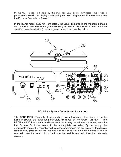
In the SET mode (indicated by the switches LED being illuminated) the processparameter shown in the display is the analog set point programmed by the operator intothe Process Controller software.In the READ mode (LED not illuminated), the value displayed is the monitored analogoutput (the actual value at that given moment) reported to the Process Controller by thespecific controlling device (pressure gauge, mass flow controller, etc.)23910MARCH <strong>CS</strong>-<strong>1701</strong>2314 1546 561181278 71212213 16 17 18 1920FIGURE 4.- System Controls <strong>and</strong> Indicators7,8. DECR/INCR. Two sets of two switches, one set for parameters displayed on theLEFT DISPLAY, the other for parameters displayed on the RIGHT DISPLAY. TheDECR <strong>and</strong> INCR momentary switches are used to vary the value of the analog set pointthe Process Controller sends to the appropriate controller. By depressing theappropriate switch the controller will increase or decrease the set value on the displaylogrithmically (first by altering the value of the ones column until a value of ten isreached, then the tens column until one hundred is reached, then the hundredscolumn).25