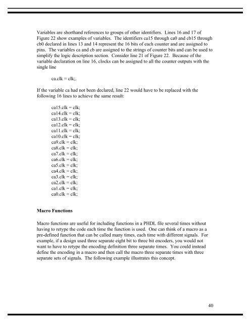
Variables are shorthand references to groups of other identifiers. Lines 16 and 17 ofFigure 22 show examples of variables. The identifiers ca15 through ca0 and cb15 throughcb0 declared in lines 13 and 14 represent the 16 bits of each counter and are assigned topins. The variables ca and cb are assigned to the strings of counter bits and can be used tosimplify the logic description section. Consider line 21 of Figure 22. Because of thevariable declaration on line 16, clocks can be assigned to all the counter outputs with thesingle lineca.clk = clk;.If the variable ca had not been declared, line 22 would have to be replaced with thefollowing 16 lines to achieve the same result:ca15.clk = clk;ca14.clk = clk;ca13.clk = clk;ca12.clk = clk;ca11.clk = clk;ca10.clk = clk;ca9.clk = clk;ca8.clk = clk;ca7.clk = clk;ca6.clk = clk;ca5.clk = clk;ca4.clk = clk;ca3.clk = clk;ca2.clk = clk;ca1.clk = clk;ca0.clk = clk;Macro FunctionsMacro functions are useful for including functions in a PHDL file several times withouthaving to retype the code each time the function is used. One can think of a macro as apre-defined function that can be called many times, each time with different signals. Forexample, if a design used three separate eight bit to three bit encoders, you would notwant to have to retype the encoding definition three separate times. You could insteaddefine the encoding in a macro and then call the macro three separate times with threeseparate sets of signals. The following example illustrates this concept.40
Module macrotstTitle 'Using macro to for three separate 8b to 3b encoders'5DECLARATIONS"Eight bit inputs to encoders10a7..a0b7..b0c7..c0pin;pin;pin;"Three bit encoded outputs15aout2..aout0 pin istype 'com,buffer';bout2..bout0 pin istype 'com,buffer';cout2..cout0 pin istype 'com,buffer';"Create the macro202530encode macro (a7,a6,a5,a4,a3,a2,a1,a0,aout2,aout1,aout0){truth_table ([?a7,?a6,?a5,?a4,?a3,?a2,?a1,?a0] -> [?aout2,?aout1,?aout0])[ 0, 0, 0, 0, 0, 0, 0, 1 ] -> [0,0,0];[ 0, 0, 0, 0, 0, 0, 1, 0 ] -> [0,0,1];[ 0, 0, 0, 0, 0, 1, 0, 0 ] -> [0,1,0];[ 0, 0, 0, 0, 1, 0, 0, 0 ] -> [0,1,1];[ 0, 0, 0, 1, 0, 0, 0, 0 ] -> [1,0,0];[ 0, 0, 1, 0, 0, 0, 0, 0 ] -> [1,0,1];[ 0, 1, 0, 0, 0, 0, 0, 0 ] -> [1,1,0];[ 1, 0, 0, 0, 0, 0, 0, 0 ] -> [1,1,1];};"Create three separate encoders using the macro35encode (a7,a6,a5,a4,a3,a2,a1,a0,aout2,aout1,aout0);encode (b7,b6,b5,b4,b3,b2,b1,b0,bout2,bout1,bout0);encode (c7,c6,c5,c4,c3,c2,c1,c0,cout2,cout1,cout0);end40Figure 2441
- Page 1 and 2: XPLA Designer
- Page 3 and 4: XPLA Designer version 2.1 User’s
- Page 5 and 6: SCL Brief .........................
- Page 7 and 8: ARITHMETIC CIRCUIT: 4 X 4 MULTIPLIE
- Page 9 and 10: the user through this design proces
- Page 11 and 12: Device FittingDevice fitting is whe
- Page 13 and 14: Chapter 2 Installing XPLA DesignerS
- Page 15 and 16: Chapter 3XPLA TM Architecture Overv
- Page 17 and 18: The XPLA TM architecture is very ac
- Page 19 and 20: 5ProgrammableANDArray55...Figure 6S
- Page 21 and 22: Chapter 4Getting Started with XPLA
- Page 23 and 24: New design filenames must use a .ph
- Page 25 and 26: the CPLD utilization and pinout. Th
- Page 27 and 28: more information. The simulator is
- Page 29 and 30: defined without returning to the Ch
- Page 31 and 32: Using the ProgrammerIf a programmer
- Page 33 and 34: Reserved WordsThe following keyword
- Page 35 and 36: Order of OperationsFigure 21 define
- Page 37 and 38: Header SectionThe header section of
- Page 39: The header of all PHDL files must s
- Page 43 and 44: dirloadcount_enabclkpin;pin;pin;pin
- Page 45 and 46: "Declare the outputscount_out = [p1
- Page 47 and 48: is illegal because buried1 cannot b
- Page 49 and 50: "Create a variable for counter outp
- Page 51 and 52: MODULE adderTITLE ‘Two four bit a
- Page 53 and 54: n1 = q3.q & q2.q;count.ar = rst # n
- Page 55 and 56: dir pin;c15..c0pin istype 'reg';"De
- Page 57 and 58: in them directing the state diagram
- Page 59 and 60: 5055606570758085state s2:when (BRAK
- Page 61 and 62: [input state 3] :> [output state 3]
- Page 63 and 64: if (TL ) then s3else if (TR) then s
- Page 65 and 66: The simulator utilizes five logic l
- Page 67 and 68: Figure 33Description of Simulator m
- Page 69 and 70: This command allows the operator to
- Page 71 and 72: Figure 37Del SignalThis command wil
- Page 73 and 74: Add BusThis command will allow the
- Page 75 and 76: Figure 43Set ValueThis command allo
- Page 77 and 78: Figure 45Figure 4677
- Page 79 and 80: Figure 4879
- Page 81 and 82: Figure 50Transition CheckThis comma
- Page 83 and 84: Figure 52To measure the difference
- Page 85 and 86: • Events [+, -]• Create [Bus, C
- Page 87 and 88: Figure 61Press the Create Bus butto
- Page 89 and 90: Figure 68• Practice Design Simula
- Page 91 and 92:
Figure 74The Demo design comes with
- Page 93 and 94:
Figure 76Now click on the run butto
- Page 95 and 96:
Statements that handle signals, dat
- Page 97 and 98:
DescriptionFormatPT Print Title PT
- Page 99 and 100:
Chapter 7 Controlling the Fitting P
- Page 101 and 102:
wide logic functions using 1 or up
- Page 103 and 104:
MODULE count_16TITLE '16-bit Loadab
- Page 105 and 106:
Figure 88As one can see from Figure
- Page 107 and 108:
that may be summed for any macrocel
- Page 109 and 110:
Chapter 8PHDL Language ReferenceThe
- Page 111 and 112:
a,b,c,doutpin;pin istype 'com,inver
- Page 113 and 114:
when (in1 == 1) & (in2 == 1) then o
- Page 115 and 116:
equationsDescriptionThe reserved wo
- Page 117 and 118:
state [1,1]: goto [0,0];endif-then-
- Page 119 and 120:
Multiple if-then-else structureModu
- Page 121 and 122:
endistypeDescriptionThe istype stat
- Page 123 and 124:
macroDescriptionThe reserved word m
- Page 125 and 126:
signal_namenode istype ‘attribute
- Page 127 and 128:
XPLA property 'dut on';inoutpin;pin
- Page 129 and 130:
State indicates the state that is b
- Page 131 and 132:
state [0,1]: out = 1;if (in1 == 1)
- Page 133 and 134:
Module whenthenTitle 'Example of si
- Page 135 and 136:
out1.c = clk;out2.c = clk;when (in1
- Page 137 and 138:
out.c = clk;s1.c = clk;state_diagra
- Page 139 and 140:
Figure 92 shows the simulation mode
- Page 141 and 142:
* Simple SCL file (any comment is O
- Page 143 and 144:
Data Fields1. A data field consists
- Page 145 and 146:
3-State (pull-up or pull-down) resi
- Page 147 and 148:
This process is repeated until all
- Page 149 and 150:
FFinishFormatFThe Finish command te
- Page 151 and 152:
IFVCondition Check on a VariableFor
- Page 153 and 154:
Example:||SU TIME = 10000LIST UNDEF
- Page 155 and 156:
This command is used to reinitializ
- Page 157 and 158:
B set to 1C set to 0D set to 1* Now
- Page 159 and 160:
SU TIME = *+500Assuming an actual t
- Page 161 and 162:
Appendix BDevice Pin Out Configurat
- Page 163 and 164:
PZ3064/PZ5064 44 Pin PLCCPin Name N
- Page 165 and 166:
PZ3064/PZ5064 68 Pin PLCCPin Name N
- Page 167 and 168:
PZ3064/PZ5064 100 Pin PQFPPIN NAME
- Page 169 and 170:
PZ3128/PZ5128 100 Pin PQFPPIN NAME
- Page 171 and 172:
PZ3128/PZ5128 160 Pin PQFPPIN NAME
- Page 173 and 174:
8-Bit Shift RegisterModule _8bshift
- Page 175 and 176:
8-Bit Adder - High LevelMODULE adde
- Page 177 and 178:
4-Bit Adder with Carry in and Carry
- Page 179 and 180:
Bidirectional I/O’sMODULE bidirec
- Page 181 and 182:
16-Bit Counter - Low Levelmodule cn
- Page 183 and 184:
}}else{}else when (dir == 1) then{c
- Page 185 and 186:
16-Bit Gray Code Countermodule gcnt
- Page 187 and 188:
& !q5 & !q4 & !q3 & !q2 & !q1 & !q0
- Page 189 and 190:
& q5 & !q4 & !q3 & !q2 & !q1 & !q0
- Page 191 and 192:
4-Bit Gray Code Countermodule gray4
- Page 193 and 194:
Timer/Countermodule p2" Timer/Count
- Page 195 and 196:
16-Bit Loadable Binary Counter - 2
- Page 197 and 198:
O9.T = CE & !LOAD & O8.Q & O7.Q & O
- Page 199 and 200:
& Q7.Q & Q6.Q & Q5.Q & Q4.Q & Q3.Q
- Page 201 and 202:
Serial CRC Generator using a 16-Bit
- Page 203 and 204:
8-Bit Loadable Data RegisterMODULE
- Page 205 and 206:
"dst24 = ^h05; unused state"dst25 =
- Page 207 and 208:
MPRSTn)MPRSTn)MPRSTn)MPRSTn)MPRSTn)
- Page 209 and 210:
# ((dst == dst21) & !DRAMCSn & MPRD
- Page 211 and 212:
MODULE m16_8High Level Implementati
- Page 213 and 214:
Datapath Circuit - Two repsmodule p
- Page 215 and 216:
Small State Machine - 8 inputs, 8 r
- Page 217 and 218:
state START1:if (inp1 == ^h3C) then
- Page 219 and 220:
module p5Arithmetic Circuit: 4 x 4
- Page 221 and 222:
1-Bit Accumulatormodule p6" 1--bit
- Page 223 and 224:
# D9 & Q8.Q);B25 = (Q11.Q & D10# D1
- Page 225 and 226:
A7_1.D = AS & A15 & A14 & A13 & !A1
- Page 227 and 228:
DRAM Refresh CounterModule refreshT
- Page 229 and 230:
state rfust5:state rfust6:state rfu
- Page 231 and 232:
Thunderbird Tailight Control Circui
- Page 233 and 234:
Denver International Air Traffic Co
- Page 235 and 236:
Appendix DError MessagesThis append
- Page 237 and 238:
2600 Control signals has pterms. C
- Page 239 and 240:
2345 File line : unknown token .C
- Page 241 and 242:
5030 Entries in truth table do not
- Page 243 and 244:
5175 Line : Constant has been decl
- Page 245 and 246:
3248: Pin feedback for signal is i
- Page 247 and 248:
Logical Errors3210: Design exceeds
- Page 249 and 250:
Appendix ZAbout this manualThis man
- Page 251:
company. It was rumored that Reno l