Maintenance & Inspection Guide Leaded ROLâ¢200 ... - Johnstech
Maintenance & Inspection Guide Leaded ROLâ¢200 ... - Johnstech
Maintenance & Inspection Guide Leaded ROLâ¢200 ... - Johnstech
- No tags were found...

You also want an ePaper? Increase the reach of your titles
YUMPU automatically turns print PDFs into web optimized ePapers that Google loves.
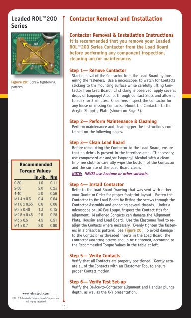
<strong>Leaded</strong> ROL200SeriesContactor Removal and InstallationContactor Removal & Installation InstructionsIt is recommended that you remove your <strong>Leaded</strong>ROL200 Series Contactor from the Load Boardbefore performing any component inspection,cleaning and/or maintenance.Figure 20: Screw tighteningpatternStep 1— Remove ContactorStart removal of the Contactor from the Load Board by looseningthe fasteners. Use a microscope, to watch for Contactssticking to the mounting surface while carefully lifting Contactorfrom Load Board. If sticking is observed, apply severaldrops of Isopropyl Alcohol through Contact Slots and allow itto soak for 2 minutes. Once free, inspect the Contactor forany loose or missing Contacts. Mount the Contactor to theAcrylic Shipping Plate (shown on Page 5).Step 2— Perform <strong>Maintenance</strong> & CleaningPerform maintenance and cleaning per the instructions containedon the following pages.RecommendedTorque Valuesin.-lb. Nm0-80 1.0 0.112-56 2.0 0.234-40 5.0 0.56M1.4 x 0.3 0.4 0.04M1.6 x 0.35 0.6 0.06M2 x 0.40 1.3 0.15M2.5 x 0.45 2.5 0.28M3 x 0.5 4.5 0.51M4 x 0.7 8.0 0.90Step 3— Clean Load BoardBefore remounting the Contactor to the Load Board, ensurethat no debris is present in the interface area. If necessary,use compressed air and/or Isopropyl Alcohol with a cleanlint-free cloth to carefully wipe the bottom of the Contactorand the surface of the Load Board clean.NOTE: NEVER use Acetone or other solvents.Step 4— Install ContactorRefer to the Load Board Drawing that was sent with eitheryour Quote or Order for proper footprint layout. Fasten theContactor to the Load Board by fitting the screws through theContactor Assembly and engaging several threads. Under amicroscope or 10X Eye Loupe, inspect the Contact tips foralignment. Misaligned Contacts can damage the AlignmentPlate, Housing and Load Board. Use the Elastomer Tool to realignthe Contacts where necessary. Evenly tighten the fastenersin a crisscross pattern. See Figure 20. To avoid damageto the Contactor or threaded inserts in the Load Board, theContactor Mounting Screws should be tightened, according tothe Recommended Torque Values in the table at left.Step 5— Verify ContactsVerify that all Contacts are properly positioned. Gently actuateall of the Contacts with an Elastomer Tool to ensureproper Contact motion.www.johnstech.com©2010 <strong>Johnstech</strong> International CorporationAll rights reserved.16Step 6— Verify Test Set-upVerify the Device-to-Contactor alignment and Handler plungedepth, as well as the X-Y presentation.