Seismic 2D Reflection Processing and Interpretation of ... - Posiva
Seismic 2D Reflection Processing and Interpretation of ... - Posiva
Seismic 2D Reflection Processing and Interpretation of ... - Posiva

You also want an ePaper? Increase the reach of your titles
YUMPU automatically turns print PDFs into web optimized ePapers that Google loves.
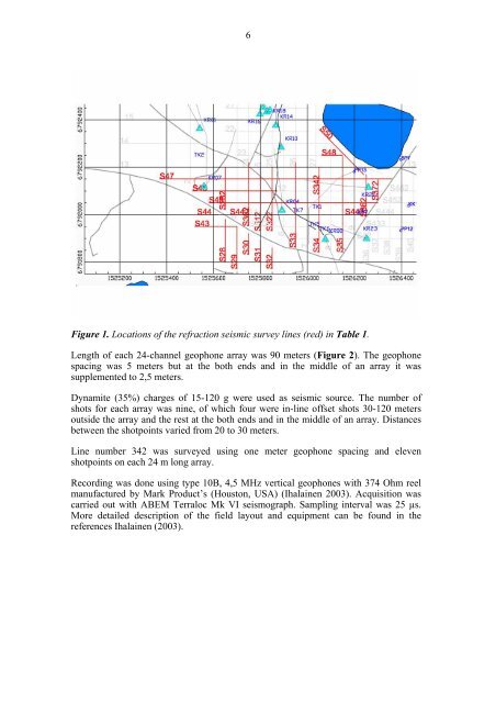
6Figure 1. Locations <strong>of</strong> the refraction seismic survey lines (red) in Table 1.Length <strong>of</strong> each 24-channel geophone array was 90 meters (Figure 2). The geophonespacing was 5 meters but at the both ends <strong>and</strong> in the middle <strong>of</strong> an array it wassupplemented to 2,5 meters.Dynamite (35%) charges <strong>of</strong> 15-120 g were used as seismic source. The number <strong>of</strong>shots for each array was nine, <strong>of</strong> which four were in-line <strong>of</strong>fset shots 30-120 metersoutside the array <strong>and</strong> the rest at the both ends <strong>and</strong> in the middle <strong>of</strong> an array. Distancesbetween the shotpoints varied from 20 to 30 meters.Line number 342 was surveyed using one meter geophone spacing <strong>and</strong> elevenshotpoints on each 24 m long array.Recording was done using type 10B, 4,5 MHz vertical geophones with 374 Ohm reelmanufactured by Mark Product’s (Houston, USA) (Ihalainen 2003). Acquisition wascarried out with ABEM Terraloc Mk VI seismograph. Sampling interval was 25 µs.More detailed description <strong>of</strong> the field layout <strong>and</strong> equipment can be found in thereferences Ihalainen (2003).