Seismic 2D Reflection Processing and Interpretation of ... - Posiva
Seismic 2D Reflection Processing and Interpretation of ... - Posiva
Seismic 2D Reflection Processing and Interpretation of ... - Posiva

Create successful ePaper yourself
Turn your PDF publications into a flip-book with our unique Google optimized e-Paper software.
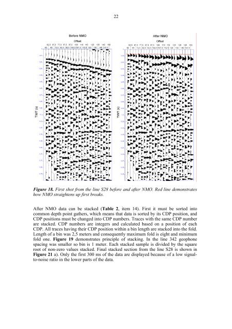
22Figure 18. First shot from the line S28 before <strong>and</strong> after NMO. Red line demonstrateshow NMO straightens up first breaks.After NMO data can be stacked (Table 2, item 14). First it must be sorted intocommon depth point gathers, which means that data is sorted by its CDP position, <strong>and</strong>CDP positions must be changed into CDP numbers. Traces with the same CDP numberare stacked. CDP numbers are integers <strong>and</strong> calculated based on a position <strong>of</strong> eachCDP. All traces having their CDP position within a bin length are stacked into the fold.Length <strong>of</strong> a bin was 2,5 meters <strong>and</strong> consequently maximum fold is eight <strong>and</strong> minimumfold one. Figure 19 demonstrates principle <strong>of</strong> stacking. In the line 342 geophonespacing was smaller so bin is 1 meter. Each stacked sample is divided by the squareroot <strong>of</strong> non-zero values stacked. Final stacked section from the line S28 is shown inFigure 21 a). Only the first 300 ms <strong>of</strong> the data are displayed because <strong>of</strong> a low signalto-noiseratio in the lower parts <strong>of</strong> the data.