Seismic 2D Reflection Processing and Interpretation of ... - Posiva
Seismic 2D Reflection Processing and Interpretation of ... - Posiva
Seismic 2D Reflection Processing and Interpretation of ... - Posiva

Create successful ePaper yourself
Turn your PDF publications into a flip-book with our unique Google optimized e-Paper software.
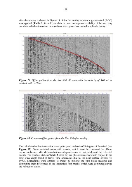
18after the muting is shown in Figure 14. After the muting automatic gain control (AGC)was applied (Table 2, item 11) to data in order to improve visibility <strong>of</strong> late-arrivingevents in which attenuation or wavefront divergence has caused amplitude decay.Figure 13. Offset gather from the line S28. Airwave with the velocity <strong>of</strong> 340 m/s ismarked with red line.Figure 14. Common <strong>of</strong>fset gather from the line S28 after muting.The calculated refraction statics were quite good on basis <strong>of</strong> lining up <strong>of</strong> P-arrival (seeFigure 12). Some residual errors still remain, which must be corrected for. Theseerrors can be seen after deconvolution as displacements in first breaks <strong>and</strong> the reflectedevents. The residual statics (Table 2, item 12) are plus-minus errors with respect to thelong wavelength trend <strong>of</strong> travel time anomalies due to the near-surface effects (Li1999). Corrections were applied to traces by picking the first break maxima <strong>and</strong>computing their differences to the theoretical first breaks, which were computed duringthe refraction statics.