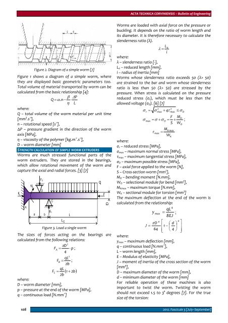
ACTA TECHNICA CORVINIENSIS – Bulletin of EngineeringWorms are loaded with axial force on the pressure orbuckling. It depends on the ratio of worm length andits diameter. It is therefore necessary to calculate theslenderness ratio (λ).Figure 2. Diagram of a simple worm [7]Figure 1 shows a diagram of a simple worm, wherethey are displayed basic geometric parameters too.Total volume of material transported by worm can becalculated from the basic relationship [4]:β ΔPQ = α.n− ⋅η Lwhere:Q – total volume of the worm material per unit time[mm 3 .s ‐1 ],n – rotational speed [s ‐1 ],∆P – pressure gradient in the direction of the wormaxis [MPa],η – viscosity of the polymer [kg.m ‐1 .s ‐1 ],D – worm diameter [mm]STRENGTH CALCULATION OF SIMPLE WORM EXTRUDERSWorms are much stressed functional parts of theworm extruders. They are stored in the bearings,which allow rotational movement of the worm andcapture the axial and radial forces. [3] [7]Figure 3. Load a single wormThe sizes of forces acting on the bearings arecalculated from the following relations:2DFA= π ⋅ p ;4qLFB = 2b;qLF C = ( 1 + 2b)2bwhere:D – worm diameter [mm],p – pressure at the end of the worm [MPa],q – continuous load [N.mm ‐1 ]2L λ = 0iwhere:λ – slenderness ratio [‐],L 0 – reduced length [mm],i – radius of inertia [mm]Worms whose slenderness ratio exceeds 50 (λ> 50)are strained to the bar and worm whose slendernessratio is less than 50 (λ> 50) are stressed by thepressure. When stress is calculated on the pressurereduced stress (σ r ), which must be less than theallowed voltage (σ D ). [6] [7]2max2maxσ r = σ + 4τ≤σDF MσOmax = σ + σ O = + ;S WOMKmaxτ max =Wwhere:σ r – reduced stress [MPa],σ max – maximum normal stress [MPa],τ max – maximum tangential stress [MPa],σ D – maximum possible stress [MPa],F – axial force applied to the worm [N],S – Cross‐section worm [mm 2 ],M O – bending moment [N.mm],W O – selectional module for bend [mm 3 ],M Kmax – maximum torque [N.mm],W K – sectional module for torsion [mm 3 ]The maximum deflection at the end of the worm iscalculated from the relationship:4qLy max = ;8EJ44πD⎡ ⎛ d ⎞ ⎤J = ⎢1− ⎜ ⎟ ⎥64 ⎢⎣⎝ 4 ⎠ ⎥⎦where:y max – maximum deflection [mm],q – continuous load [N.mm ‐1 ],L – worm length [mm],E – Modulus of elasticity [MPa],J – moment of inertia of the cross section of the worm[mm 4 ],D – maximum diameter of the worm [mm],d – minimum diameter of the worm [mm]For reliable operation of these machines is alsoimportant to twist the worm. Twisting the wormshould not exceed 1.5 to 3° degrees [7]. For the truesize of the torsion:K1082012. Fascicule 3 [July–September]
ACTA TECHNICA CORVINIENSIS – Bulletin of Engineering° MKL180ϕ max = ⋅ ≤ϕDGJ πwhere:φ ° max – maximum tortion [°],M K – torque [N.mm ‐1 ],L – worm length [mm],G – modulus of elasticity [MPa],φ D – the maximum possible tortion[°]CONCLUSIONSDesign and calculation of components of themachinery is a creative activity using theoretical andpractical experience. This activity must be gearedmainly to meet the requirements. At present, virtuallyall areas of design activities supported by computertechnology that can be effectively used in the designof machinery components particularly in theconstruction of technical documentation and fieldstrength calculations.REFERENCES[1.] Gašpár, Š.: Implementácia programu AutodeskInventor 2009 pri riešení rovinne zaťažených, statickyurčitých priamych konštrukcií. ERIN 2009: 3. ročníkmedzinárodní konference, Ostrava, VŠB‐TU, 2009,ISBN 978‐80‐248‐1982‐2[2.] Batešková, E. – Maščenik, J. – Haľko, J. – Gašpár, Š:Device for measurement of clamped joints frictiontorque. In: Technological Developments inNetworking, Education and Automation. ‐ Dordrecht:Springer, 2010, p. 417 – 419, ISBN 978‐90‐481‐9150‐5[3.] Horvát, T. – Pavlenko, S. – Palko, A.: Použitieprogramu Autodesk Inventor pri vytváraní adimenzovaní hriadeľov, 2010. In: Vzdelávanie učiteľovstredných odborných škôl v nových európskychnormách : zborník referátov informačno‐tématickéhoseminára : 21. október 2010, Prešov FVT TU, s. 110‐114.,ISBN 978‐80‐553‐0549‐3[4.] Liptáková, T. – Alexy, P. – Gondár, E. – Khunová, V.:Polymérne technické materiály, ŽU Žilina, 2009, 182 s.[5.] Maščenik, J. – Haľko, J.: Proposal and calculation ofworm gear with PC upport /Návrh a výpočet závitovkys podporou PC /, In: ERIN 2009. ‐ Ostrava : VŠB‐TU, ‐ISBN 9788024819822[6.] Pavlenko, S. – Haľko, J. – Maščenik, J. – Nováková,M.:Navrhovanie súčastí strojov s podporou PC, 1. vyd.– Prešov : FVT TU, 2008, 347 s.,ISBN 978‐80‐553‐0166‐2[7.] Ragan, E. a kol.: Vstrekovanie plastických hmôt, FVTTU Prešov, 2008, 548 s., ISBN 978‐80‐553‐0102‐0ACTA TECHNICA CORVINIENSIS – BULLETIN of ENGINEERINGACTA TECHNICA CORVINIENSIS – BULLETIN of ENGINEERINGISSN: 2067‐3809 [CD‐Rom, online]ISSN: 2067‐3809 [CD‐Rom, online]copyright © UNIVERSITY POLITEHNICA TIMISOARA,FACULTY OF ENGINEERING HUNEDOARA,5, REVOLUTIEI, 331128, HUNEDOARA, ROMANIAhttp://acta.fih.upt.ro2012. Fascicule 3 [July–September] 109
- Page 2 and 3:
ACTA TECHNICA CORVINIENSIS- BULLETI
- Page 4 and 5:
ACTA TECHNICA CORVINIENSIS - Bullet
- Page 6 and 7:
ACTA TECHNICA CORVINIENSIS - Bullet
- Page 8 and 9:
Regional Editors from MALAYSIAAbdel
- Page 10 and 11:
Imre TIMÁRUniversity of Pannonia,
- Page 12 and 13:
Ioan MILOŞANTransilvania Universit
- Page 14 and 15:
Member from GREECENicolaos VAXEVANI
- Page 16 and 17:
ACTA TECHNICA CORVINIENSIS - Bullet
- Page 18 and 19:
ACTA TECHNICA CORVINIENSIS - Bullet
- Page 20 and 21:
ACTA TECHNICA CORVINIENSIS - Bullet
- Page 22 and 23:
two decades are seismically deficie
- Page 24 and 25:
ACTA TECHNICA CORVINIENSIS - Bullet
- Page 26 and 27:
ACTA TECHNICA CORVINIENSIS - Bullet
- Page 28 and 29:
The Euler ecuation about the condit
- Page 30 and 31:
ACTA TECHNICA CORVINIENSIS - Bullet
- Page 32 and 33:
examination centre of the Hungarian
- Page 34 and 35:
ACTA TECHNICA CORVINIENSIS - Bullet
- Page 36 and 37:
elieve that they are communicating
- Page 38 and 39:
converting the data also increases
- Page 40 and 41:
REFERENCES[1.] Bhavyesh Divecha, Aj
- Page 42 and 43:
In addition, API (Application Progr
- Page 44 and 45:
The new protocol has to be implemen
- Page 46 and 47:
compressor, the now hot and highly
- Page 48 and 49:
Figure 7. Pressure ratio of evapora
- Page 50 and 51:
Physical data model (MFD) is obtain
- Page 52 and 53:
The new project which now includes
- Page 54 and 55:
Figure 3. Materials evolutionThe pr
- Page 56 and 57:
(GPa) and weight used in the textil
- Page 58 and 59: ACTA TECHNICA CORVINIENSIS - Bullet
- Page 60 and 61: ACTA TECHNICA CORVINIENSIS - Bullet
- Page 62 and 63: A machine vision‐guided plant sen
- Page 64 and 65: During the experiment, non‐unifor
- Page 66 and 67: espectively velocities hodograph (v
- Page 68 and 69: generation and thermal‐diffusion
- Page 70 and 71: 70(Pr−1)=bGm( R −cPr)( − M+c
- Page 72 and 73: 72Figure 12: Sherwood Number for di
- Page 74 and 75: ACTA TECHNICA CORVINIENSIS - Bullet
- Page 76 and 77: The hardware components offer the p
- Page 78 and 79: Markers 1 (t=‐60 ms) and 2 (t=‐
- Page 80 and 81: ACTA TECHNICA CORVINIENSIS - Bullet
- Page 82 and 83: compensation, apply dynamic control
- Page 84 and 85: A. Impact on transmission line prot
- Page 86 and 87: [12.] W.H. Zhang, S.J. Lee, M.S. Ch
- Page 88 and 89: Substituting equations (2), (3), (4
- Page 90 and 91: ACTA TECHNICA CORVINIENSIS - Bullet
- Page 92 and 93: the tribological experiment to simu
- Page 94 and 95: It is difficult to determine temper
- Page 96 and 97: ACTA TECHNICA CORVINIENSIS - Bullet
- Page 98 and 99: where: “ν ” represents the con
- Page 100 and 101: Figure 10. The velocity field in a
- Page 102 and 103: made on demand. In this type of pro
- Page 104 and 105: traditional MANET routing protocol
- Page 106 and 107: and classification,” In Journal o
- Page 110 and 111: ACTA TECHNICA CORVINIENSIS - Bullet
- Page 112 and 113: ACTA TECHNICA CORVINIENSIS - Bullet
- Page 114 and 115: ACTA TECHNICA CORVINIENSIS - Bullet
- Page 116 and 117: equipped with tube made from stainl
- Page 118 and 119: Fig. 10 ‐ The die, the blank hold
- Page 120 and 121: desktop, it must be based on runtim
- Page 122 and 123: ACTA TECHNICA CORVINIENSIS - Bullet
- Page 124 and 125: database, which makes it possible t
- Page 126 and 127: technology - „Applied logistics
- Page 128 and 129: increase in one of the factors lead
- Page 130 and 131: ACTA TECHNICA CORVINIENSIS - Bullet
- Page 132 and 133: ACTA TECHNICA CORVINIENSIS - Bullet
- Page 134 and 135: ACTA TECHNICA CORVINIENSIS - Bullet
- Page 136 and 137: ACTA TECHNICA CORVINIENSIS - Bullet
- Page 138 and 139: ACTA TECHNICA CORVINIENSIS - Bullet
- Page 140 and 141: ACTA TECHNICA CORVINIENSIS - Bullet