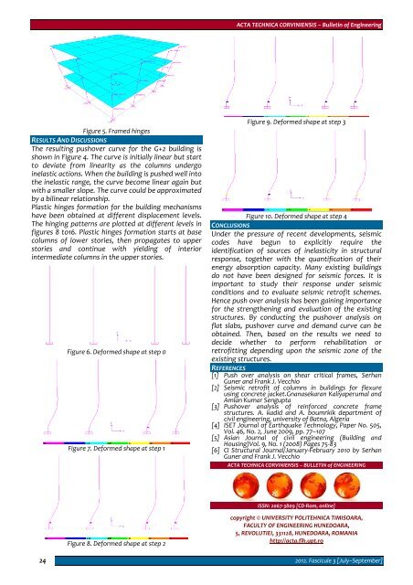
ACTA TECHNICA CORVINIENSIS – Bulletin of EngineeringFigure 5. Framed hingesRESULTS AND DISCUSSIONSThe resulting pushover curve for the G+2 building isshown in Figure 4. The curve is initially linear but startto deviate from linearity as the columns undergoinelastic actions. When the building is pushed well intothe inelastic range, the curve become linear again butwith a smaller slope. The curve could be approximatedby a bilinear relationship.Plastic hinges formation for the building mechanismshave been obtained at different displacement levels.The hinging patterns are plotted at different levels infigures 8 to16. Plastic hinges formation starts at basecolumns of lower stories, then propagates to upperstories and continue with yielding of interiorintermediate columns in the upper stories.Figure 6. Deformed shape at step 0Figure 7. Deformed shape at step 1Figure 9. Deformed shape at step 3Figure 10. Deformed shape at step 4CONCLUSIONSUnder the pressure of recent developments, seismiccodes have begun to explicitly require theidentification of sources of inelasticity in structuralresponse, together with the quantification of theirenergy absorption capacity. Many existing buildingsdo not have been designed for seismic forces. It isimportant to study their response under seismicconditions and to evaluate seismic retrofit schemes.Hence push over analysis has been gaining importancefor the strengthening and evaluation of the existingstructures. By conducting the pushover analysis onflat slabs, pushover curve and demand curve can beobtained. Then, based on the results we need todecide whether to perform rehabilitation orretrofitting depending upon the seismic zone of theexisting structures.REFERENCES[1] Push over analysis on shear critical frames, SerhanGuner and Frank J. Vecchio[2] Seismic retrofit of columns in buildings for flexureusing concrete jacket.Gnanasekaran Kaliyaperumal andAmlan Kumar Sengupta[3] Pushover analysis of reinforced concrete framestructures. A. kadid and A. boumrkik department ofcivil engineering, university of Batna, Algeria[4] ISET Journal of Earthquake Technology, Paper No. 505,Vol. 46, No. 2, June 2009, pp. 77–107[5] Asian Journal of civil engineering (Building andHousing)Vol. 9, No. 1 (2008) Pages 75‐83[6] CI Structural Journal/January‐February 2010 by SerhanGuner and Frank J. VecchioACTA TECHNICA CORVINIENSIS – BULLETIN of ENGINEERINGISSN: 2067‐3809 [CD‐Rom, online]Figure 8. Deformed shape at step 2copyright © UNIVERSITY POLITEHNICA TIMISOARA,FACULTY OF ENGINEERING HUNEDOARA,5, REVOLUTIEI, 331128, HUNEDOARA, ROMANIAhttp://acta.fih.upt.ro242012. Fascicule 3 [July–September]
THE EVACUATION OF PRESSURE MOULDS AS PROGRESSIVEDEVELOPMENTS OF DIE CASTING PROCESS1.Jozef MAŠČENIK1.TECHNICAL UNIVERSITY OF KOŠICE, FACULTY OF MANUFACTURING TECHNOLOGIES, DEPT. OF TECHNICAL DEVICES DESIGN, PRESOV, SLOVAKIAABSTRACT: In these days in foundry branch there is a rapid development of sectors of special casting technology with the aimto increase the quality and the efficiency of pressure casting production. In the production of castings cast under pressurethere is an increased attention to the internal homogeneity of castings, where in accordance with the specifics of thistechnology are the most common casting errors internal cavities (bubbles, pores). Internal homogeneity of pressurecasting, characterized by the extent of porosity can be affected by the setup of technological parameters of pressurecasting and last but not least by vacuuming the molds, that means to exhaust air and gases from the mold cavity.KEYWORDS: die casting, vacuum, porosity, quality of castingINTRODUCTIONTechnology of casting metal in a vacuum was beingput into the production process already in the middleof last century in the U.S., where three systems weredeveloped (NELMAR, OHSE, Morton). From the pointof then state of the techniques its practical use was atone point (closing of exhaust valve) insufficiently met.This technology was introduced to mass production in80s in Japan. Today, the world leader in metal castingin a vacuum is vacuum systems developed by the SwissFONDAREX.Figure 1. Comparison of conventionaland vacuum pressure casting metalare not fully taken by venting form system. Dependingon the nature of the vent system and pistoncompression force in the filling chamber, the pressurein the mold cavity is increasing during the first stageof compression to the value of 0.3 MPa. In otherphases of compression, these values may be doubledor even tripled.(fig. 1a) Venting the mold cavity by gasand air diversion gas using vacuum causes a reductionin back pressure in the mold cavity. In this wayantipressure rarely exceeds 0.02 MPa [1,2].The principle design of degassing pressure form isshown schematically in Fig. 2, where with the help ofvalve the valve suction device is formed, which has towithin a few milliseconds, when the casting processtakes place, drain away air and gases from the moldcavity. Exhaustion lasts throughout the molding cycle[3].THE METHODOLOGY OF EXPERIMENTS AND EQUIPMENTFor the realization of experiments the compressedcasting machine FRECH DAW125F was used, designedfor casting non‐ferrous metals with a verticallyarranged filling chamber and degassing of thepressure casting mold was realized by a vacuumdevice FONDAREX. Analysis of the impact of degassingthe pressure molds on casting porosity has beenobserved on the cast on Figure 3.Figure 2. Scheme of vacuuming process [4]By the conventional method of casting during themolding phase in the inlet system and the mold cavity,anti‐ pressure of gases and vapors is formed whichduring the short period of time sufficient compressionFigure 3. Analyzed CastingThe tested analyzed casting is made from an alloyZnAl4Cu1, whose chemical composition responded toEN 1774 and is listed in the table 1.© copyright FACULTY of ENGINEERING ‐ HUNEDOARA, ROMANIA 25
- Page 2 and 3: ACTA TECHNICA CORVINIENSIS- BULLETI
- Page 4 and 5: ACTA TECHNICA CORVINIENSIS - Bullet
- Page 6 and 7: ACTA TECHNICA CORVINIENSIS - Bullet
- Page 8 and 9: Regional Editors from MALAYSIAAbdel
- Page 10 and 11: Imre TIMÁRUniversity of Pannonia,
- Page 12 and 13: Ioan MILOŞANTransilvania Universit
- Page 14 and 15: Member from GREECENicolaos VAXEVANI
- Page 16 and 17: ACTA TECHNICA CORVINIENSIS - Bullet
- Page 18 and 19: ACTA TECHNICA CORVINIENSIS - Bullet
- Page 20 and 21: ACTA TECHNICA CORVINIENSIS - Bullet
- Page 22 and 23: two decades are seismically deficie
- Page 26 and 27: ACTA TECHNICA CORVINIENSIS - Bullet
- Page 28 and 29: The Euler ecuation about the condit
- Page 30 and 31: ACTA TECHNICA CORVINIENSIS - Bullet
- Page 32 and 33: examination centre of the Hungarian
- Page 34 and 35: ACTA TECHNICA CORVINIENSIS - Bullet
- Page 36 and 37: elieve that they are communicating
- Page 38 and 39: converting the data also increases
- Page 40 and 41: REFERENCES[1.] Bhavyesh Divecha, Aj
- Page 42 and 43: In addition, API (Application Progr
- Page 44 and 45: The new protocol has to be implemen
- Page 46 and 47: compressor, the now hot and highly
- Page 48 and 49: Figure 7. Pressure ratio of evapora
- Page 50 and 51: Physical data model (MFD) is obtain
- Page 52 and 53: The new project which now includes
- Page 54 and 55: Figure 3. Materials evolutionThe pr
- Page 56 and 57: (GPa) and weight used in the textil
- Page 58 and 59: ACTA TECHNICA CORVINIENSIS - Bullet
- Page 60 and 61: ACTA TECHNICA CORVINIENSIS - Bullet
- Page 62 and 63: A machine vision‐guided plant sen
- Page 64 and 65: During the experiment, non‐unifor
- Page 66 and 67: espectively velocities hodograph (v
- Page 68 and 69: generation and thermal‐diffusion
- Page 70 and 71: 70(Pr−1)=bGm( R −cPr)( − M+c
- Page 72 and 73: 72Figure 12: Sherwood Number for di
- Page 74 and 75:
ACTA TECHNICA CORVINIENSIS - Bullet
- Page 76 and 77:
The hardware components offer the p
- Page 78 and 79:
Markers 1 (t=‐60 ms) and 2 (t=‐
- Page 80 and 81:
ACTA TECHNICA CORVINIENSIS - Bullet
- Page 82 and 83:
compensation, apply dynamic control
- Page 84 and 85:
A. Impact on transmission line prot
- Page 86 and 87:
[12.] W.H. Zhang, S.J. Lee, M.S. Ch
- Page 88 and 89:
Substituting equations (2), (3), (4
- Page 90 and 91:
ACTA TECHNICA CORVINIENSIS - Bullet
- Page 92 and 93:
the tribological experiment to simu
- Page 94 and 95:
It is difficult to determine temper
- Page 96 and 97:
ACTA TECHNICA CORVINIENSIS - Bullet
- Page 98 and 99:
where: “ν ” represents the con
- Page 100 and 101:
Figure 10. The velocity field in a
- Page 102 and 103:
made on demand. In this type of pro
- Page 104 and 105:
traditional MANET routing protocol
- Page 106 and 107:
and classification,” In Journal o
- Page 108 and 109:
ACTA TECHNICA CORVINIENSIS - Bullet
- Page 110 and 111:
ACTA TECHNICA CORVINIENSIS - Bullet
- Page 112 and 113:
ACTA TECHNICA CORVINIENSIS - Bullet
- Page 114 and 115:
ACTA TECHNICA CORVINIENSIS - Bullet
- Page 116 and 117:
equipped with tube made from stainl
- Page 118 and 119:
Fig. 10 ‐ The die, the blank hold
- Page 120 and 121:
desktop, it must be based on runtim
- Page 122 and 123:
ACTA TECHNICA CORVINIENSIS - Bullet
- Page 124 and 125:
database, which makes it possible t
- Page 126 and 127:
technology - „Applied logistics
- Page 128 and 129:
increase in one of the factors lead
- Page 130 and 131:
ACTA TECHNICA CORVINIENSIS - Bullet
- Page 132 and 133:
ACTA TECHNICA CORVINIENSIS - Bullet
- Page 134 and 135:
ACTA TECHNICA CORVINIENSIS - Bullet
- Page 136 and 137:
ACTA TECHNICA CORVINIENSIS - Bullet
- Page 138 and 139:
ACTA TECHNICA CORVINIENSIS - Bullet
- Page 140 and 141:
ACTA TECHNICA CORVINIENSIS - Bullet